1
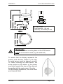
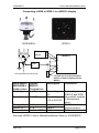
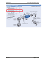
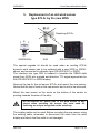
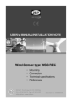
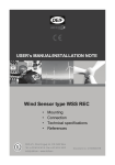
USER’s MANUAL/INSTALLATION NOTE
Wind Sensor type WSS & WSS-L
•
•
•
•
•
Mounting
Connecting
Replace an old sensor
Technical specifications
References
Document no.: 4189350026F
WSS/WSS-L
User’s Manual/Installation Note
Table of contents
1.
INTRODUCTION ......................................................................... 3
UNPACKING.................................................................................... 4
LEGAL INFORMATION AND RESPONSIBILITY ...................................... 4
2.
MOUNTING THE WIND SENSOR ............................................. 5
PLACING OF THE WIND SENSOR...................................................... 5
BIRD AVOIDANCE KIT (OPTIONAL) .................................................... 7
3.
CABLE CONNECTIONS............................................................. 8
THE WSS WIND SENSOR CABLE CONNECTIONS .............................. 8
CONNECTING A WSS OR WSS-L TO A WSDI-2 DISPLAY ................ 9
CONNECTOR KIT ASSEMBLY (OPTIONAL)....................................... 10
4.
DIMENSIONS ............................................................................ 12
5.
REPLACEMENT OF AN OLD WIND SENSOR....................... 13
6.
TECHNICAL SPECIFICATION ................................................. 16
7.
REFERENCES........................................................................... 19
DEIF A/S
Page 2 of 19
WSS/WSS-L
User’s Manual/Installation Note
1. Introduction
This document provides guidelines for mounting and connecting the
WSS and WSS-L static wind sensor. The WSS can be directly
connected to the DEIF WSDI-2 wind display to form a complete wind
system.
WSS or WSS-L can also be used as wind sensor for previous DEIF
wind displays like WSDI and 879, but in that case it must be connected
via an interface box.
The sensor may also be used as a component in a larger system; in
that case the system must have a free RS485 or RS422 input with
NMEA0183 capability.
The ultrasonic wind measuring system used in the WSS is a fast
responding and accurate system designed for measurement of wind
speed and wind direction on-board ships.
The sensor is based on three ultrasonic transducers arranged in a
triangle for measuring of wind speed and wind direction. By measuring
the time it takes for a set of ultrasound bursts to travel from each
transducer to the other two, the wind speed and direction can be
calculated.
The wind sensor is available in two different versions:
• The WSS with a built-in heater, which will automatically engage
when risk of icing occurs during low temperatures.
• The WSS-L without the heater is intended for applications in
geographic areas where the risk of icing is very low or where
occasional dropouts caused by icing are acceptable.
Important: Please be aware that the term WSS will represent both
WSS and WSS-L if no specific mentioning of the WSS-L is made.
DEIF A/S
Page 3 of 19
WSS/WSS-L
User’s Manual/Installation Note
Unpacking
The WSS sensor is delivered in a cardboard box. To protect the
delicate sensor heads, it is important to store it in the box until
mounting.
Do not hit, squeeze or try to
remove the three black
rubber hoods!
The sensor is protected against ESD (static electricity), but it is
recommended to avoid static discharge trough the connection wires
during installation.
Legal information and responsibility
DEIF takes no responsibility for installation or operation of the wind
measuring system. If there is any doubt about how to install or operate
the WSS, the company responsible for the installation or the operation
of the product must be contacted.
The units are not to be opened by unauthorised personnel.
If opened anyway, the warranty will be lost.
DEIF A/S
Page 4 of 19
WSS/WSS-L
User’s Manual/Installation Note
2. Mounting the wind sensor
Placing of the wind sensor
Ideally, the wind sensor should be placed far from large objects that
might influence the measuring results; however, in practice this is
normally not possible on-board a ship. The best result is achieved by
placing the wind sensor at the top of a mast in the opposite end of the
superstructure.
Placing the sensor just above the superstructure is disadvantageous,
especially where the superstructure consists of wide side faces, over
which the wind is forced. This may result in turbulence, velocities and
wind directions that are out of proportion to the actual, undisturbed wind
speed and wind direction.
Keep away from the funnel.
The wind sensor is intended for installation on a vertical socket or a
tube using the stainless steel tap mounting base. See the drawing
below for dimensions of the tap. The tap must not be removed from
the wind sensor, as this will damage the waterproof sealing and
warranty will become void.
Do not expose the plastic part of the wind sensor to any
torque when mounting the sensor. The tools used for
fastening are only to be applied on the actual tap.
DEIF A/S
Page 5 of 19
User’s Manual/Installation Note
¾” pipe thread:
Outer diameter: 1.04 inch
(26.4mm), 14 threads per inch.
114.0
127.0
49.5
82.4
149.8
25.0
198.0
WSS/WSS-L
IMPORTANT!
The stainless steel mounting base on the WSS sensor
must be connected to earth (e.g. the steel hull).
To ensure that the display represents the
precise wind direction relative to the ship,
the wind sensor must be aligned correctly.
I.e. when mounting the wind sensor, the
arrow printed on the bottom of the sensor
must point towards the stem of the ship and
be parallel with the centre axis of the ship.
On land-based installations, the arrow must
point towards North.
DEIF A/S
Page 6 of 19
WSS/WSS-L
User’s Manual/Installation Note
Bird avoidance kit (optional)
The Bird avoidance kit is designed to reduce the risk of birds landing on
the WSS or WSS-L and thereby interfering with measurements or even
damaging the sensitive ultrasonic transducer heads (the black rubber
heads may attract some bird’s attention).
The kit is an optional extra and is installed on top of the sensor.
The spike system is designed not to hurt birds, but simply create a
barrier to make it difficult for birds to land on top of the sensor.
Please note, that the kit does not provide complete protection against
birds, but especially large sea birds will not be able to land, while small
birds may still be able to squeeze inn. Small birds may interrupt the
wind measurement but will not be able to damage the sensor.
The shape and location of the spikes have been designed so that the
interference with wind measurements is negligible.
It is recommended to use the kit if there is a high accumulation of birds
in the area where the sensor is used.
When the kit is mounted on the WSS sensor, more
snow may be able to accumulate on top of the sensor
and it may melt slower.
Installation of the kit
1. Position the metal ring with spikes
around the stainless steel top plate of
the WSS/WSS-L sensors. Position it so
that the spikes do not block the direct
paths between the three black rubber
heads, see picture.
2. Secure the metal ring using the M3x6
screw provided. It is recommended to
secure the screw from loosening due to
vibrations with a drop of Loctite® super
glue or equivalent (not included in the
kit) and tighten the screw all the way in.
3. Check that the kit sits tightly on the
WSS/WSS-L
DEIF A/S
Page 7 of 19
WSS/WSS-L
User’s Manual/Installation Note
3. Cable connections
The wind sensor is supplied with 2 metres fixed cable. From factory,
the cable is connected to the sensor via a waterproof gland, and this
must not be replaced by another cable. The cable can be extended by
using the connection box kit or the IP67 connector kit (both optional).
In order to protect the wind sensor and the personnel in the best
possible way from lightning strokes, use a lightning rod installed with
the tip at least one metre above the wind sensor. The lightning rod
must be properly grounded in compliance with all applicable safety
regulations. The wind sensor cable screen and the extension cable
screen must be connected.
For further protection of the cable between the wind sensor and the
connection box, as well as the installation cable between the
connection box and the interface box, it is recommended to use a
metal conduit pipe. If the instrument is installed in a metal panel, this
panel has to be carefully earthed, as well as the instrument itself.
Suitable extension cable is available from DEIF at any length between
1 and 300 meter. Alternatively, an installation cable, e.g. UL2464
2
18AWG4C + AE, 4 x 0.75mm screened, can be used. The max.
length is 300m, and maximum 70nF capacity between the signal
conductors.
The WSS wind sensor cable connections
Cable
colour
Black
Red
Orange
Brown
Shield
Function
Supply
voltage
RS485
comm.
Cable shield
Note
+
A
B
9 - 31V DC supply for the
WSS wind sensor
Wind speed and direction data
output
Is connected to the stainless
steel tap inside the WSS.
No supply voltage must be present during installation of the
wind sensor, as this will damage the wind sensor.
DEIF A/S
Page 8 of 19
WSS/WSS-L
User’s Manual/Installation Note
Connecting a WSS or WSS-L to a WSDI-2 display
WSS/WSS-L
WSDI-2
DC power source
+
WSDI-2
1.
2.
….
7.
8.
9.
Conn.
kit
(Optional)
Ground (Earth) the sensor tap
T
The data bus must be terminated
with the resistor supplied with the
WSDI-2
Wind sensor
WSS/WSS-L
Cable colour
Black (-)
Display
WSDI-2
Terminal no.:
1. 0V
Red
2. VCC
(+)
Orange (A)
Brown (B)
Screen
7. A
9. B
8. Data GND
Description
Comments
Aux. voltage:
0V
Aux. voltage:
+12 or 24V DC
Aux. voltage to
WSDI-2 and WSS
are parallel-coupled
in the terminal
block
RS485 data
communication
Cable screen
Data A
Data B
Cable screen
See also: WSDI-2 User’s Manual/Installation Note no. 4189350032.
DEIF A/S
Page 9 of 19
WSS/WSS-L
User’s Manual/Installation Note
Connection of other equipment
One standard NMEA0183 input for a VDR or integrated navigation
system can be connected to terminal A and B (see also chapter 6 –
Interface). It is recommended to use a NMEA-buffer if more than one
NMEA input has to be connected.
Connector kit assembly (Optional)
The connectors must be soldered onto the cable according to the
following instructions:
WSS/WSS-L
fixed cable
Connector
pin no.
WSS extension
cable
Male
connector
Female
connector
Plug Male 7 pin.
10 22 00 00 52
Plug female 7 pin.
10 22 00 00 53
Screw cap male,
10 29 92 00 02
Screw cap female,
10 29 92 00 03
Black (-)
Red (+)
Orange
Brown
Screen
DEIF A/S
●
●
●
●
●
1
2
3
4
5
Black (-)
Red (+)
Orange
Brown
Screen
Signal
comments
●
●
●
●
●
30V DC Supply
for WSS/WSS-L
RS485 Comm.
from WSS/WSS-L
Cable screen
Page 10 of 19
WSS/WSS-L
User’s Manual/Installation Note
Measures are in mm.
DEIF A/S
Page 11 of 19
WSS/WSS-L
User’s Manual/Installation Note
DEIF A/S
¾” pipe thread:
Outer diameter: 1.04 inch
(26.4mm), 14 threads per
inch.
114.0
127.0
49.5
82.4
149.8
198.0
4. Dimensions
Page 12 of 19
WSS/WSS-L
User’s Manual/Installation Note
5. Replacement of an old wind sensor
type 879.3c by the new WSS
Replacing 879.3c
WSS/WSS-L
WSI
879.50/879.521 or WSDI
The special upgrade kit should be used when an existing 879.3c
dynamic wind sensor has to be replaced with a new WSS or WSS-L
sensor and connected to a display type 879.50/879.521 or WSDI.
The interface box type WSI is needed to translate the RS485 data
signal from WSS into a speed and direction TTL signal appropriate for
the 879.50/879.521 or WSDI display.
Remove the tap for the old sensor 879.3c and mount the new sensor.
Notice that the tap is fixed on the new sensor and is not to be removed.
Mount the new sensor so the arrow on the bottom of the sensor is
pointing towards the stem of the ship.
Do not expose the plastic part of the wind sensor to any
torque when mounting the sensor; the tools used for
fastening are only to be applied on the actual tap.
The existing cable can be used. Before mounting the new sensor using
the existing cable, remember to disconnect the cable from the wind
display and check that the cable is not damaged.
DEIF A/S
Page 13 of 19
WSS/WSS-L
User’s Manual/Installation Note
The sensor is equipped with a 2m cable, this cable is connected to the
existing cable using a junction box (normally already mounted).
The interface box can be mounted anywhere between the sensor and
the display(s), but the following must be taken into consideration: the
interface box has to be supplied from a 24V DC/1.25A source and
mounted indoor, for which reason it is recommended to mount the
interface box close to the existing display(s).
Wind sensor
WSS
Cable colour
Interface box
WSI
Terminal no.:
Black (-)
Red (+)
Orange (A)
Brown (B)
Screen
9 - WSS supply
7 + WSS supply
4 Input A
5 Input B
61 – Power
2 + Power
12 - (0V)
11 D
10 S
Display
WSDI
Terminal
no.:
Comments
30V DC supply for
the WSS
RS485 comm.
from WSS
Cable screen (earth)
Aux. supply 18-32V
DC, 1.25A
2 0V
4 Direction
3 Speed
5 Screen
AC
AC
GND/Earth
1 +5V
A Signal
B Return
Screen
9
10
11
Wind direction (D)
and wind speed (S)
Screen
Aux. supply 110V
AC or 220V AC
Ground
+5V DC for external
mode shift/dimmer
NMEA0183 output
External mode
shift/dimmer, see
document no.
4189350009
IMPORTANT!
The stainless steel mounting base of the WSS sensor
must be connected to earth (e.g. the steel hull).
DEIF A/S
Page 14 of 19
WSS/WSS-L
User’s Manual/Installation Note
4.5
WSI interface box dimensions:
85.0
61.0
75.0
99.7
110.0
Before the replacement is carried out, it is recommended to carefully
read the User's Manual/Installation Note (this document).
DEIF A/S
Page 15 of 19
WSS/WSS-L
User’s Manual/Installation Note
6. Technical specification
Sensors are designed according to the standards below
Power supply
Power
consumption
Interface
Data sentence
Wind speed
Wind direction
DEIF A/S
12/24V (9.0…31.2V DC)
WSS-L and WSS with inactive heating
element: < 0.1W
WSS with maximum heating < 15W
RS485 (I/O) operation:
The bus should be terminated with 120 to 200
ohm for pure RS485 operation.
Standards
NMEA 0183
ver. 2.x-3.0
Combined RS485 (I/O) and NMEA0183 (I)
operation:
A combination of up to ten RS485 (I/O) and
one NMEA0183 listeners can be connected to
the WSS data interface at the same time.
The data line must be terminated with a 200 to
250ohm resistor to obtain > +/- 2.1V output
necessary for a standard NMEA0183 input
circuit to work. The NMEA0183 input load must
be < 2mA @ +/- 2V.
NOTE: A NMEA-buffer is recommended if
connection of more than one standard NMEA
input is needed.
$WIMWV – Wind speed and direction data
$WIXDR – Transducer Measurement
NMEA 0183
Response
ver. 3.0
$WITXT – Error messaging
For details see doc. no. 4189350028 Appendix
to User's Manual, Wind measuring system
Range:
0….116 KTS (0….60m/s)
Resolution:
0.1 Knots
Accuracy:
0…68 KTS: ±0.6 KTS or
±3%, whichever is greater
> 68 KTS: ±5%
Range:
Resolution:
Accuracy:
o
0…. 360 continuously
o
1
±3% in relation to wind
direction
Page 16 of 19
WSS/WSS-L
Update interval
Start-up time
Connection
Mounting
User’s Manual/Installation Note
1 second
< 5 sec. from power on to valid data output
2
2 meter 4 x 0.75mm screened cable type
UL2464 18AWG/4C+DW+AL/MY+Jacket.
The 2m cable is fixed mounted on the sensor
and is open-ended.
¾” pipe thread: Outer diam: 1.04 inch
(26.4mm), 14 threads per inch.
Compass safety
0.2 meter
distance
Protection
Relative
humidity
Pressure
IEC 945 and
EN 60945
IEC 529 and
EN 60529
EN/IEC
60068-1/2
IP66
0…100%
600…1100hPa
WSS operating range:
-52…+60°C (class approved for: -25…+60°C)
WSS-L operating range:
0…60°C (see note)
Temperature
EN 60051
Storage (both): -60…+70°C
Note: WSS-L has no automatic heating
element to prevent ice, the sensor will work
below 0°C but it will depend on weather
conditions.
Vibration test
Safety
EMC
Housing
Weight
DEIF A/S
3…13.2Hz:
2mm (peak-peak)
13.2…100Hz: 0.7g
3…15Hz:
+ 2.5mm (peak)
15…50Hz:
2.3g
Cat.III, poll.dg.2, 550V AC rms, 50Hz,
1 minute
CE-marked for industrial environment
Wind sensor housing: Polycarbonate +10%
glass fibre
Mounting tap: Corrosion-resistant stainless
steel
EN 60945,
EN/IEC600682-6 and
DNV Class A
GL curve 4 for
masts
EN 61010-1
EN 61000-11/2/3/4
UL94 V0
0.8 kg
Page 17 of 19
WSS/WSS-L
User’s Manual/Installation Note
Dimensions,
cardboard box
450 x 315 x 230
Approvals
Type-approved according to:
(See www.deif.com for certificates and details)
Accessories
GL, DNV,
CCS, RS and
GOST-R
IP66 Connection box kit: IP66 Connection box
w/ cable glands and screw terminals to extend
the sensor cable with an extension cable
IP67 Connector kit: water tight male and
female connector for soldering to respectively
the sensor cable and the extension cable.
Extension cable: 1 to 300m shielded cable
DEIF id.no.1020230016
Bird avoidance kit: Spike kit to prevent birds
from interrupting the wind measurements or in
worst case from damaging the sensor.
DEIF A/S
Page 18 of 19
WSS/WSS-L
User’s Manual/Installation Note
7. References
For more details see:
WSDI-2 User’s Manual/Installation Note, document no. 4189350032.
Appendix to User’s Manual, Wind measuring systems, document no.
4189350028.
Documentation is available on www.deif.com – Download centre.
DEIF A/S reserves the right to change any of the above.
DEIF A/S
Page 19 of 19