1
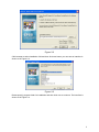
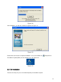
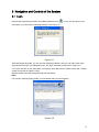
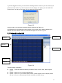
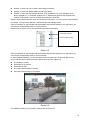
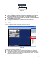
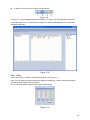
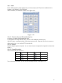
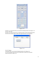
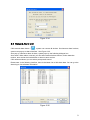
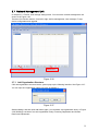
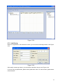
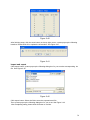
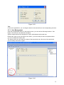
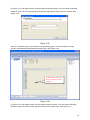
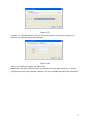
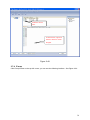
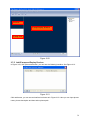
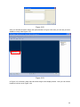
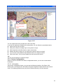
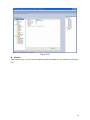
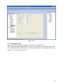
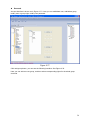
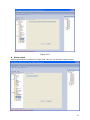
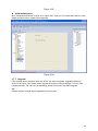
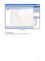
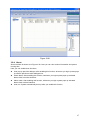
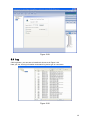
Enterprise Pro Surveillance System User’s Manual 1 Table of Contents 1 FEATURES......................................................................................................... 6 2 INSTALLATION................................................................................................... 8 2.1 Environment ........................................................................................................................................... 8 2.2 Installation............................................................................................................................................... 8 2.3 Un-installation ...................................................................................................................................... 10 3 NAVIGATION AND CONTROLS OF THE SYSTEM......................................... 12 3.1 Login ...................................................................................................................................................... 12 3.2 Network Monitor Unit........................................................................................................................... 13 3.2.1 Device............................................................................................................................................... 15 3.2.2 Color ................................................................................................................................................. 16 3.2.3 PTZ ................................................................................................................................................... 17 3.2.4 Plan ................................................................................................................................................... 21 3.3 E-map .................................................................................................................................................... 26 3.4 Network File Unit ................................................................................................................................. 27 3.4.1 Search .............................................................................................................................................. 27 3.4.2 Download ......................................................................................................................................... 27 3.4.3 Playback........................................................................................................................................... 28 3.5 Network Backup Unit........................................................................................................................... 29 3.6 Network Alarm Unit ............................................................................................................................. 31 3.7 Network Management Unit................................................................................................................. 32 3.7.1 Add Organization Structure ........................................................................................................... 32 2 3.7.2 Add Device....................................................................................................................................... 33 3.7.3 User Management .......................................................................................................................... 35 3.7.4 E-map ............................................................................................................................................... 38 3.7.5 Add E-map and Deploy Devices................................................................................................... 39 3.7.6 Device Configuration ...................................................................................................................... 42 3.7.7 Upgrade............................................................................................................................................ 62 3.8 3.8.1 Network Keyboard .......................................................................................................................... 64 3.8.2 Language ......................................................................................................................................... 65 3.8.3 Health Report .................................................................................................................................. 66 3.8.4 About................................................................................................................................................. 67 3.9 4 System .................................................................................................................................................. 63 Log ......................................................................................................................................................... 68 MORE INFORMATION ..................................................................................... 69 3 Welcome Thank you for using our Enterprise Pro Surveillance System! This user’s manual is designed to be a reference tool for operation of your system. Here you can find information about this surveillance system features and functions. Note: Any changes of this manual made to the actual product are subjects to no further notification. 4 Introduction & Configuration Enterprise Pro Surveillance System is central management software of strong performance, distribution structure. It integrates multiple-windows, multiple-users, multiple-languages, audio talk, video conference, multiple-level E-map, alarm centre. It is compatible with other extension products like network matrix system. This software has e-map function, user-friendly interface. It is easy to operate and convenient to configure. Enterprise Pro Surveillance System is compatible with multiple devices of various series and types (such as DVR, IPC, NVS and etc). This manual is mainly about the software operation. Please refer to corresponding user’s manual of different devices for detailed information. This manual is also for the people who have basic operation and experience and is in charge of planning, executing and checking Enterprise Pro Surveillance System installation. Enterprise Pro Surveillance System supports the following devices: DVRs, IP cameras, IP domes, NVS, IP storage device and etc. 5 1 Features Enterprise Pro Surveillance System has the following features: z Professional File System Special file system is suitable for real-time surveillance. System adopts pre-assigned technology and buffering technology and support RAID to guarantee system working stability and efficiency. z Structure Management & User and Right Management System support multiple-level structure management, user management and right management. z Device Intelligent Search Support intelligent search device IP and corresponding information to reduce steps to add devices, hence enhancing system user-efficient z Support Alarm Plan Customization and Alarm Arm and Withdraw Support alarm deployment and withdraw. Support activation between surveillance and alarm modules, support device activation. z Data Interface Technology System adopts data interface technology and supports data base from large to small such as SQL、MYSQL and XML. z Support Excel Edit to add platform device(To be developed) Platform is compatible with MS Excel suitable for adding or editing large amount device. It enhances system operation efficient and greatly reduces user maintenance work. z Intelligent Video Transmission Protocol System adopts intelligent video transmission protocol to maximally use network bandwidth. Especially when the front bandwidth is limited, system can run normally and at the same time guarantee video quality z Perfect Video Surveillance Function Support the real-time surveillance, and at the same time support alarm record, motion detection record, vide playback. You can accurately control the record status in each channel. z Digital Matrix Working with decoding card and network keyboard, system can realize digital matrix. z Dynamically Adjust Decode Buffer (HD Function ) Support switch priority between video continuity and real-time monitor when you are in real-time surveillance: video continuity is to guarantee video fluency and real-time monitor is to emphasize video real-time. It is to meet client’s various demands. z Real-time Communication and File Transmission Platform supports real-time communication and file transmission function. It is easy for you to communicate. z Carrier Technology and Module Development to implement application solutions easily System adopts carrier technology, layer and module development. Full of middle ware service to support all kinds of solutions installation conveniently z Central Management Whole system data central management and data transfer function provide perfect multiple-user real-time surveillance plan. Remote users can real-time monitor or playback video via network. z Easy to Use Under right management, you can set and control each surveillance point easily via our clientend. System also integrates E-map function. 6 z High Integration System integrates other information such as alarm information and audio information z High Reliability System features special fault-tolerant function to guarantee data integrity and system reliability z Sound Expansible System adopts service-oriented architecture. It has expansible and flexibility to maximally guarantee user investment z z z z z z z z z z Support B/S Mode Support Public Net Access Support Network Administration and Load Balance Support Multiple-device Upgrade at the Same Time Support Customized Surveillance Plan and Monitor Point Fuzzy Search Support User DIY Interface and Multiple Languages Support E-map Support Matrix Function Support Network Keyboard Operation Support Compression Card Encode Units (To be developed ) 7 2 Installation 2.1 Environment We recommend the following configuration: z Hardware CPU P4 2.0G Display card: support hardware zoom such as ATI,TNT2 PRO. We recommend ATI9800 or above dual channel. 128M/128bit Network card: 100/1000M z Software For client system, we recommend Vista, Windows 2000, Windows 2003, or Windows XP. For server system, we recommend Windows 2003. 2.2 Installation Double click General_EPSS_ChnEng_Basic_IS_V4.5.0.0.R.080227.exe icon, the interface is shown as in Figure 2-1. Please click next button to continue. Figure 2-1 Here you can select destination directory. See Figure 2-2. 8 Figure 2-2 Click browser to select installation fold and then click next button you can see an interface is shown as in Figure 2-3. Figure 2-3 Please specify program folder for installation and then click next to continue. The interface is shown as in Figure 2-4. 9 Figure 2-4 After installation, you will see a window as appears in Figure 2-5. Figure 2-5 Please click close button to complete installation. You can see EPSS icon Enterprise Pro Surveillance System (Basic) is in the desktop now. See Figure 2-6. Figure 2-6 2.3 Un-installation There are two ways for you to un-install enterprise pro surveillance system. 10 z z From start to program then select Enterprise Pro Surveillance System. Please right click mouse and select un-installation. From start to control panel and then select add or remove program. Select Enterprise Pro Surveillance System and select un-installation. 11 3 Navigation and Controls of the System 3.1 Login Double click enterprise profession surveillance platform icon ( ). If it is your first time to use the system, you can see the following interface. See Figure 3-1. Figure 3-1 After selecting a language, you can see the following interface. Here you can input user name and password to log in you selected server. The log in interface is shown as in Figure 3-2. If it is your first time to use the system, you need to click add button to add a device first. Default central control server name is Local. System default username and password both are admin. Note: For security reasons please modify your password after you first logged in. Figure 3-2 12 If you have logged in before, you can see the following interface. Click Yes you can resume your previous monitor mode. If you do not want to see this dialogue box again, you can disable this function here. You can go to chapter 3.8.4 to enable this function again. Figure 3-3 After your login, you can see the network monitor interface. See Figure 3-4. Our Enterprise Pro Surveillance System consists of five function Units: Network Monitor Unit, Network File Unit, Network Alarm Unit, Network Management Unit and Log Unit. 3.2 Network Monitor Unit Section 5 Section 1 Section 2 Section 6 Section 3 Section 4 Figure 3-4 There are totally six sections: z Section 1: There are seven function keys: monitor, E-map, record, save, alarm, log and system. z Section 2: Here is for you to view channel video. z Section 3: Here is for you to select display mode. System supports various display modes. HD item is for you to select priority between real-time and video fluency. 13 z z z Section 4: Here is for you to view current help information. Section 5: Here is to display data flux and CPU status. Section 6: There are four function buttons: PTZ (Chapter 3.2.3), color (Chapter 3.2.2), device (chapter 3.2.1), and plan (chapter 3.2.4). Please note system only supports one window in full-screen. Here we recommend resolution 1024*768. Select a device name and then click connect/disconnect button, you can connect current device to network. You can see a little red -cross below the name disappeared. Click one window on you left side and then double click channel name on you right hand, you can see the corresponding video in current window. Please refer to Figure 3-5 for connection/disconnection information. Connected channel Disconnected channel Figure 3-5 Click one window on you left side and then double click channel name on you right hand, you can see the corresponding video in current window. In video window interface, you can see there are five function keys on the top right corner. On the top left corner, there are some symbols such as S2 in Figure 3-6. z S1 stands for overlay. z S2 stands for off-screen. z S3 stands for GDI. z H1 is the hard encoding of overlay. z H2 is the hard encoding of off-screen. Figure 3-6 For detailed function key information, please refer to Figure 3-7. 14 1 2 3 4 56 Figure 3-7 z z z z z z 1: Local zoom in: Click this button and then left drag the mouse in the zone to zoom in. right click mouse system restores original status. 2: Switch display mode: resize or switch to full screen mode. 3: Manual record. When you click local record button, the system begins recording and this button becomes highlighted. You can go to system -.local record to set video file path. 4: Capture picture. You can snapshoot important video. All images are memorized in system client folder \download\picture (default). 5: Audio :Turn on or off audio.(It has no relationship with system audio setup ) 6: Close video. 3.2.1 Device In Figure 3-4, click device button, the interface is shown as in Figure 3-8. Figure 3-8 There are four function keys. See Figure 3-9. z 1. Manage setting: click this button you can see an interface is shown as in Figure 3-10. z 2. Connect/Disconnect: Select a device and then click this button to connect (disconnect). z 3. Talk: select a device and then click this button to enable audio talk function. (This function is disabled during video conference process.) 15 z 4. Reboot: Here is for you to reboot current device. 1 2 3 Figure 3-9 4 In Figure 3-8, click manage setting button (Button 1 in Figure 3-9), the interface is shown as below. See Figure 3-10. Please refer to chapter 3.1 Network Management Unit for detailed operation instruction. Figure 3-10 3.2.2 Color Click color button in section 6, the interface is shown as Figure 3-11. Here you can select one channel and then adjust its brightness, contrast, hue and saturation. (Current channel border becomes green). Or you can click default button to use system default setup. Figure 3-11 16 3.2.3 PTZ Before PTZ operation, please make sure you have properly set PTZ protocol. (Please refer to chapter 3.7.6.2 Setting-> Pan/Tilt/Zoom). Click PTZ button, the interface is shown as in Figure 3-12 . Figure 3-12 3.2.3.1 Direction key and 3D positioning key In Figure 3-12, there are eight direction keys. In the middle of the eight direction keys, there is a 3D intelligent positioning key. Click SIT button, system goes back to the single screen mode. Drag the mouse in the screen to adjust section size. It can realize PTZ automatically. 3.2.3.2 Speed System supports eight-level speed. You can select from the dropdown list. Speed 2 is faster than speed 1. 3.2.3.3 Zoom/Focus/Iris Here is a sheet for you reference. Name Function key Zoom Function Function key Function Near Far Focus Near Far Iris close Open Then click advance button, you can see the following interface. See Figure 3-13. 17 Figure 3-13 In Figure 3-13, click setup button you can see the following interface. See Figure 3-14. 3.2.3.4 Auto scan In Figure 3-14, move the camera to you desired location and then click left limit button. Then move the camera again and then click right limit button to set a right limit. Figure 3-14 3.2.3.5 Pattern Click patter button, you can see the following interface .See Figure 3-15. You can input pattern value and then click start button to begin PTZ movement. System goes back to Figure 3-13. 18 After you finished camera operation, please go to Figure 3-15 to click stop. Now you have set one pattern. Figure 3-15 3.2.3.6 Preset Click preset button, the interface is shown as below. See Figure 3-16. Move the camera to your desired location and then input preset value. Click add button, you have set one preset. Figure 3-16 3.2.3.7 Auto tour Click auto tour button, the interface is shown as below. See Figure 3-17. You can input auto tour value and preset value. Click add button, you have added one preset in the tour. Repeat the above procedures you can add more presets in one tour. 19 Figure 3-17 3.2.3.8 Preset/Tour/Pattern Operation In Figure 3-13, click preset button, and then input preset number in value blank and then click ON button. Now you have enabled preset function. Click OFF to stop preset function. Other functions are similar to the preset operation. 3.2.3.9 Relating (Activation) There are three PTZ activation modes: preset activation, scan activation and tour activation. Please select one window, this window is monitor channel 1 of device 1. And then you can go to relating interface to select preset. See Figure 3-18. Here you can input value as 1 and the select alarm port 1. Click relating button to confirm current setup. From now on, whenever there is alarm from channel 1 of devcie1, the PTZ automatically goes to preset 1. Figure 3-18 3.2.3.10 PTZ Menu Please select one monitor window and then click PTZ menu item. You can see an interface is shown as in Figure 3-19. You can use four direction buttons to adjust and then click confirm button to save current setup. 20 Figure 3-19 3.2.4 Plan Click plan button, you can see the following interface. See Figure 3-20. 21 Figure 3-20 There are three function buttons. See Figure 3-21. 1. Plan management 2. Start/stop 3. Pause/resume 1 2 3 Figure 3-21 3.2.4.1 Add Small Plan Click add button, system pops up the following interface. See Figure 3-22. 22 Double click camera to add Figure 3-22 Click add button in Figure 3-22, you can see an interface is shown as in Figure 3-23. You can input a small plan name such as Entrance and select window amount from the dropdown list such as 1. Click OK to add one small plan. Figure 3-23 Now you can see there is a small plan Entrance on your left side. Click + icon before the channel name, you can view the newly added four channels. Click one device channel on you left side and then click channel number on you right side. System pops up dialogue box for you to set interval. See Figure 3-24. 23 Step 3 System pops up the dialogue box for you to input interval. Step 2 Step 1 Select one channel Double click channel number here. here. Figure 3-24 Now you can see there is a new small plan. See Figure 3-25. You can repeat the above steps to add more small plans. 24 Figure 3-25 3.2.4.2 Add Large Plan In Figure 3-25, click add button below large plan column. System pops up the following interface. See Figure 3-26. Figure 3-26 You can input large plan name such as Front Door and then click OK button. Click add button, system pops up a dialogue box for you to input start time and select corresponding small plan name from the dropdown list. See Figure 3-27. Click OK button, you can see system has added a new large plan. You can repeat the above steps to add more small plans into this big plan. 25 Step 1 Click add button here Step 2 System pops up the dialogue box for you to input small plan name. Figure 3-27 In Figure 3-28, you can see a large plan front door consists of two small plans: Entrance and Exit. Figure 3-28 After you created a large plan, you can click a plan name and then click start button ( ) to enable a large plan. 3.3 E-map Please refer to chapter 3.7.4. 26 3.4 Network File Unit Here is for you search, playback or download file. Click record button, the interface is shown as below. See Figure 3-29. Figure 3-29 3.4.1 Search In Figure 3-29 you can select file type, start time/end time, device name and corresponding channel, then click search button you can see result on you right side. See Figure 3-30. If you want to search local PC video file, please enable record function and then select “record source” as storage server. Select the channel and then click search button. Now you can see the results on your right side. Figure 3-30 3.4.2 Download You can select one or more files in the search result column to download to your local PC. During download procedure, you can refer to progress bar. See Figure 3-31. 27 Figure 3-31 3.4.3 Playback In the search result interface, there are two ways for you to play back video. z Select file name and then click playback button. z Double click file name The playback interface is shown as below. See Figure 3-32. In player interface, there are following items: z 1: Frame rate. There are nine options:1f/2f/3f/6f/12f/25f/50f/75f/100f, You can click z z z z z z z z z corresponding pane to select. 2 :Play 3:Pause 4:Stop 5 :Start record 6: Previous file 7:Backward 8 Forward 9 Next file 10: Capture: Here is for you to snapshot important image. z z z z 11: Sound: + is to increase volume, - is to decrease volume. Click icon “ ” to turn on or off volume. 12: Current frame rate: Here you can view current frame rate. 13: Current status: Here you can view play status bar, play mode and volume status (on or off). 14: Convert to AVI: System can convert the video file of suffix name such as mp4, Dav, mpeg, 264 to avi format. z z z z 15: Full-screen: There are two ways: click full-screen button to review in full-screen mode. The other way is to double click current window to review in full-screen. 16: Play mode: shuffle or repeat. 17: Change language: The player supports two languages: English/Chinese. System pops up dialogue box asking for restarting. Click OK, system automatically restart. 18: Parameter setting. You can set parameter setup/. 28 Figure 3-32 3.5 Network Backup Unit Click save button, the interface is shown as in Figure 3-33. You can follow the steps listed below to set: z Enable auto record function and then select package address and time and then click apply button. z Double click camera on your right side to add a channel z Select detailed time period and mode. z Select device and then click apply button. 29 Double click the channel name to add. Figure 3-33 Network drivers operation: z Click network driver button in Figure 3-33, you can see an interface is shown as in Figure 3-34. You need to select a driver first. z Click browser button to select share network folder. z Input login user name and password. z Click OK button to confirm current setup. z You select current driver as record initial driver or record stop driver, the system can save files in current driver. 30 Figure 3-34 3.6 Network Alarm Unit Click network alarm button( ),system can connect all devices. So whenever there is alarm, system can pop up an alarm interface. See Figure 3-35. Auto pop up: Whenever there is alarm, system pops up the following dialogue box. Auto watch: When alarm occurred, you can select external alarm monitor, motion detection monitor, auto monitor the both alarms or does not auto monitor. Click advanced button you can select prompt audio sound. Please note: In the following interface, there is the latest 10o to 200 alarm data. You can g to the alarm log to view all alarm information. Figure 3-35 31 3.7 Network Management Unit In chapter 3.2.1 Device, click manage setting button. You can see a network management unit shown as in Figure 3-36. There are five function buttons, from left to right: device management, user manager, E-map, device configuration and upgrade. Add organization structure Add device Figure 3-36 3.7.1 Add Organization Structure Click add organization structure button, system pops up the following interface. See Figure 3-37. You can input one organization name here such as building 1. Figure 3-37 Select building1 and then click add button again, you can add a sub-organization entity. In Figure 3-38, Builiding1 consists of two sub-organization entity: Financing Department and Human Resources Department. 32 Figure 3-38 3.7.2 Add Device Select one organization, click add device button, you can see the following interface .see Figure 3-39. Figure 3-39 Click modify camera type button, you can see the interface is shown as in Figure 3-40. If you are using a speed dome, please check speed dome item. For other devices, please select normal camera. 33 Figure 3-40 After finishing setup, click the save button on the top right corner, system pops up the following interface. Please click OK to update the information. See Figure 3-41. Figure 3-41 Import and export Click import button, system pops up the following dialog box for you to select corresponding .xls file. See Figure 3-42. Figure 3-42 Click export button. Select the fold to save the exported excel file. Then system pops up the following dialog box for you to set. See Figure 3-43. After completing setup, please click OK button to confirm. 34 Figure 3-43 Tips: In structure organization, you can drag the device in the device list to the corresponding structure. 3.7.3 User Management Click user management button on the top left corner, you can see the following interface. See Figure 3-44.Here you can add user and group. System adopts three-level management: super, administrator and normal user. Please note, there is only one super user “admin”, you can modify its name and password but you can not delete this super user. The higher-level user can modify the rights of the lower-level user. But user of the same-level can not modify each other’s rights. Figure 3-44 35 In Figure 3-44, click option button and then select create group item. You can see the following interface. Here you can select group level and then input group name such as overseas. See Figure 3-45. Figure 3-45 After you created a group, you can select corresponding rights. There are mainly four right groups: monitor/network playback/record/user right. See Figure 3-46. In blank section, right click mouse to select or cancel all rights. Figure 3-46 In Figure 3-44, click option button and then select create user item. You can see the following interface. Here you need to select a group for the newly created user. See Figure 3-47. 36 Figure 3-47 In Figure 3-47, click finish button, then you can see an interface is shown as in Figure 3-48. Here you can input user name and password. Figure 3-48 Now, you can select user rights. See Figure 3-49. Please note, user rights setup here can not exceed current group rights setup! E.g.: if current group does not have right to monitor channel-3, you can not enable this right for this user either! 37 Select the device here. In blank section, right click mouse to select or cancel all rights. Figure 3-49 3.7.4 E-map Click E-map button on the top left corner, you can see the following interface. See Figure 3-50. 38 Preview E-map Display Window E-map List Figure 3-50 3.7.5 Add E-map and Deploy Devices In Figure 3-50, click picture edit button, you can see the following interface. See Figure 3-51. Figure 3-51 Click add button, you can see an interface is shown as in Figure 3-52. Here you can input picture name, picture description and then select picture path. 39 Figure 3-52 After you finished the above steps, click picture button in Figure 3-50. Now you can see you have added an e-map. See Figure 3-53. Figure 3-53 In Figure 3-53, left click e-map name and then drag it to the display section. Now you can see an interface is shown as in Figure 3-54. 40 Figure 3-54 In Figure 3-54 click device button, drag the channel number to the e-map and then release. You can see the following interface. See Figure 3-55. Double click the camera in the e-map list; you can enable real-time monitor function. The disabled camera has a red icon“:” below its name Tip: Move the green rectangle icon in the preview section; you can view different e-map content in display section. 41 Drag your mouse to the e-map and then release. Figure 3-55 You can repeat the above procedures to add a sub-map. If you want to implement multiple sub-e-maps setup, you can follow the procedures below: z Open one map such as map1. z Click picture button and drag map 2 to anywhere in map1. z Click map button and click map 2 to open current map z Double click device name on your right side to add one device to map 2. z You can view newly added e-map and device list in the map list section. z Click save button, now you have added one sub-map and its device. Tip: You can use one device in several e-maps. 3.7.6 Device Configuration Select one device and then click device configuration button, you can see current device information. 3.7.6.1 Information Click device configuration button, you can see the following interface. See Figure 3-56. Please note our Enterprise Pro Surveillance System integrates multiple devices and various users. The following interface may vary due to different devices you have selected. 42 Figure 3-56 z Version Click version button, you can see corresponding HDD information for your reference. See Figure 3-57. 43 Figure 3-57 z HDD Information Here you can view HDD amount, HDD status, total volume and free space. See Figure 3-58. 44 Figure 3-58 z Log Click log button, you can see an interface is shown as in Figure 3-59. Here you can view current device log information. Figure 3-59 3.7.6.2 Setting Setting includes the following items: General Encode setup Schedule RS232 Network MUL-DDNS FTP Alarm setup Detect Pan/Tilt/Zoom Configuration tool Please note: setups for different device series may vary. Please refer to the corresponding user’s manual. z General General interface is shown as in Figure 3-60. System time: Here is for you to modify system time. Please click Save after your modification 45 Data format: Here you can select data format from the dropdown list. Data separator: Please select separator such as – or /. Time format: there are two options: 24-H and 12-H. HDD full: there are two options: stop recording or overwrite the previous files when HDD is full. Pack duration: Here you can select file size. Default setup is 60 minutes. Device No.: when you are using one remote control to manage multiple DVRs, you can give these DVRs serial numbers respectively. Click address button in your remote control and then input the correct device number, now you can manage the DVR now. Video standard: PAL. (for your reference only) Figure 3-60 z Encode Setup Encode setup includes the following items. See Figure 3-61. Here you can select Channel: Here is for you to select a channel. Channel name: Modify channel name. Data stream: Regular and extra data stream. AV enable: Video/Audio. System only displays video by default. You need to manually enable audio function. Bit rate: There are two options: CBR and VBR. Frame rate: The value ranges from 1f/s to 25f/s. Compression: There are two options: H.264 and MPEG 4. Resolution: D1/HD1/DCIF/CIF 46 Quality: The value ranges from 1 to 6. The level 6 is the best video quality. Figure 3-61 z Schedule Schedule includes the following interface. See Figure 3-62. When DVR boots up, it is in 24-hour continuous record. In this interface you can set record type, record time and period. Record type includes regular record(R), motion detection record (M) and alarm record (A). Channel: select the channel number you desire. Week: you can select from the dropdown list. Or you can select at the bottom of the interface. Prerecord: system can record the three to five seconds video before activating the record operation into the file.(Depends on data size) Period: There are six periods for you to set. Please click set button of the corresponding period See Figure 3-63.Please note all the setup here shall be in one day. E.g. 00.00 to 24.00. 47 Figure 3-62 Figure 3-63 Tip: After you finished setup for one channel, you can click “save as” button, system pops up the following interface. See Figure 3-64.Now you can copy one channel setup to other channels. 48 Figure 3-64 z Network Network interface is shown as in Figure 3-65. This interface includes the following items: Max TCP: The value ranges from 0 to 10. TCP port: default setup is 37777. Please note port 37778 is for network UDP port use only. HTTP port: default setup is 80. Enable PPPoE In remote item, enable PPPoE function and then input “PPPoE name” and “PPPoE password” you get from your ISP (Internet service provider). See Figure 3-65. Click save button, you need to restart to activate your configuration. After rebooting, DVR will connect to internet automatically. The IP in the PPPoE is the dynamic value. You can use client end software to visit current IP now. Figure 3-65 49 Enable DDNS You need a PC of fixed IP in the internet and there is the DDNS software running in this PC. In other words, this PC is a DNS (domain name server).see Figure 3-66. In remote item, enable DDNS function and then input PC IP. Click save button and then reboot device. Now you can login via DDNS. Figure 3-66 z RS232 RS232 includes the following items. See Figure 3-67. RS232 includes the following items Protocol: There are five protocols. Baud rate: Please select as you desire. Data bit: The value ranges from 5 to 8. Stop bit: There are three options: 1/1.5/2. Parity: There are three options: none/odd /even. 50 Figure 3-67 z Mul-DDNS This operation needs DVR device supported. See Figure 3-68. 51 Figure 3-68 z FTP After you completed setup here, system upload scheduled data to the specified FTP server regularly. Need device supported. In Figure 3-69, you need to input FTP server address, port, log in user name and password. Then you need to specify the destination directory to save files. z File: here you can input uploaded file length (Unit: MB) if the file is smaller than the setup value here, system upload the whole file. If the file is larger than the setup value, system only uploads the setup value data and ignores the rest data. z Interval: for one channel of the same record type if there is more than one alarm, system only uploads the first file. For example, if the interval is five minutes, then system only uploads the first alarm or motion detection file even though there are several alarms in these five minutes. If the setup is 0, then system upload all files. z Time period: Click set button, you can an interface as in Figure 3-70. You can check the box to select the file type. System supports multiple choices. Figure 3-69 52 Figure 3-70 z Alarm Setup Please note before alarm setup, you need to properly connect alarm input and output device, send address and receive address. Click save button confirm current setup. Alarm setup includes the following items. See Figure 3-71. Alarm in: Select corresponding alarm in channel Type: There are two options: normal open and normal close. Record channel: select record channel when alarm occurs. Please note you need to select alarm record in DVR schedule interface and enable schedule function in manual record interface. Alarm output: select alarm activation channel when alarm occurs. Please note channel 3 is to control +12V output. 53 Figure 3-71 z Detect Detect interface is shown as in Figure 3-72. Here includes the following items: Channel: Type: There are three types: motion detection/Video loss/Camera mask detection. Record channel: Here you can select record channel (Multiple choices). Please note you need to select alarm record in DVR schedule interface and enable schedule function in manual record interface. Region: If you select motion detection type, you can click this button to set motion detection zone. The interface is shown as in Figure 3-73. There are 192 zones (16*12). Right click mouse you can go to full-screen display mode. Do remember clicking save button in Figure 3-73 to save your motion detection zone setup. Sensitivity: There are six levels. The six-level is the highest sensitivity. Alarm output: Here you can select activated external peripheral device when alarm occurs. Figure 3-72 54 Figure 3-73 z Pan/Tilt/Zoom Pan/Tilt/Zoom interface is shown as in Figure 3-74. Please note you have properly set dome address and all connections are right. Decoder: Select the dome connected channel. Protocol: select the corresponding dome protocol.(such as DH-SD1) Address: Set corresponding dome address. Default value is 1. Please note your setup here shall comply with your dome address; otherwise you can not control the speed dome. Baud rate: Select the dome baud rate. Default setup is 9600. Data bit: Default setup is 8. Stop bit: Default setup is 1. Parity: Default setup is none. 55 Figure 3-74 z Configuration tool Here you can export or import configuration information. See Figure 3-75. Save configuration data: Click this button to save current setup as a file. Extension name is CFG. Load configuration data: Click this button to load a configuration file. The interface is shown as in Figure 3-76. You can select the file now. 56 Figure 3-75 Figure 3-76 3.7.6.3 Advanced Advanced includes the following items. See Figure 3-77. Account HDD management Alarm input Alarm output Auto maintain Video matrix Snapshoot 57 z Account Account interface is shown as in Figure 3-77. Here you can add/delete user, add/delete group, modify user or group right, modify user password. Figure 3-77 Click add group button, you can see the following interface. See Figure 3-78. Here you can add one new group, and then select corresponding rights for the whole group accounts. 58 Figure 3-78 Click add user button, you can see the following interface. See Figure 3-79. Here you can input a new user and then select corresponding rights. Please note one user must belong to one group and user right shall not exceed group rights limit. Figure 3-79 z HDD management This function needs DVR device supported. 59 Please select the HDD first and then you can see the items on your right become valid. You can check the corresponding item here. See Figure 3-80. After you completed setup, please click control HDD button, you can see the DVR begins restarting. Figure 3-80 z Alarm input Alarm input interface is shown as in Figure 3-81. Here you can set alarm input channel. 60 Figure 3-81 z Alarm output Alarm output interface is shown as in Figure 3-82. Here you can set alarm output channel. 61 Figure 3-82 z Auto maintenance Auto maintenance interface is shown as in Figure 3-83. Here you can enable auto reboot or auto delete old files function. (Need DVR supported) Figure 3-83 3.7.7 Upgrade Click upgrade button and then select the device you want to upgrade. Upgrade interface is shown as in Figure 3-84. Please select upgrade file and then click send button. You can view upgrade process. You can see corresponding prompt words after successful upgrade. Tip: System supports multiple-device upgrade at the same time. 62 Figure 3-84 3.8 System Click system button, the interface is shown as below. See Figure 3-85. System includes the following items: z Network keyboard z Language z Health report z About 63 Figure 3-85 3.8.1 Network Keyboard Meeting interface is shown as below. See Figure 3-86. You can use network or serial port to connect to network. Select network control you can use IP to connect. Select serial control you can use serial port to connect. 64 Figure 3-86 3.8.2 Language System supports multiple languages. It is scalable. See Figure 3-87. 65 Figure 3-87 3.8.3 Health Report Here you can view device name, connection status and record status. See Figure 3-88. 66 Figure 3-88 3.8.4 About About interface is shown as in Figure 3-89. Here you can view version information and system running time. Here you can enable three functions: z Auto pop up previous dialogue: after enabling this function, whenever you login system pops up resume previous monitor dialogue box. z Watch alarm: after enabling this function, whenever you login system pops up activated alarm video in monitor interface. z Alarm watch: after enabling this function, whenever you login system pops up activated alarm video in alarm interface. z Auto run: System automatically boot up after you enable this function. 67 Figure 3-89 3.9 Log Click log button, you can see an interface is shown as in Figure 3-90. Here you can view log information and search log via its type or user name. Figure 3-90 68 4 More Information If you want more information, please contact with our engineers. Note: Slight difference may be found in user interface. All designs and software here are subject to change without prior written notice. Please visit our website for more information. 69