1
User's Guide
A1200
AM/CA
(:: Commodore
User's Guide
A1200
Copyright © 1992 by Commodore Electronics Limited. All rights Reserved. This document may not, in
whole or in part, be copied, photocopied, reproduced, translated or reduced to any electronic medium or
machine readable form without prior consent, in writing, from Commodore Electronics Limited.
With this document Commodore makes no warranties or representations, either expressed, or implied,
with respect to the products described herein. The information presented herein is being supplied on an
"AS IS" basis and is expressly subject to change without notice. The entire risk as to the use of this
information is assumed by the user. IN NO EVENT WILL COMMODORE BE LIABLE FOR ANY
DIRECT, INDIRECT, INCIDENTAL, OR CONSEQUENTIAL DAMAGES RESULTING FROM ANY
CLAIM ARISING OUT OF THE INFORMATION PRESENTED HEREIN, EVEN IF IT HAS BEEN
ADVISED OF THE POSSIBILITIES OF SUCH DAMAGES. SOME STATES DO NOT ALLOW THE
LIMITATION OF IMPLIED WARRANTIES OR DAMAGES, SO THE ABOVE LIMITATIONS MAY NOT
APPLY.
Commodore and the Commodore logo are registered trademarks of Commodore Electronics Limited.
Amiga is a registered trademark, and AmigaDOS, Bridgeboard, Kickstart, and Workbench are
trademarks, of Commodore-Amiga, Inc. Hayes is a registered trademark of Hayes Microcomputer
Products, Inc. Centronics is a registered trademark of Centronics Data Computer Corp. Motorola is a
registered trademark, and 68030 and 68EC020 are trademarks, of Motorola Inc. MultiSync is a
registered trademark of NEC Technologies Inc. ARexx is a trademark of William S. Hawes. MS-DOS is
a registered trademark of Microsoft Corporation.
NOTE: This equipment has been tested and found to comply with the limits for a Class B digital device,
pursuant to Part 15 of FCC Rules. These limits are designed to provide reasonable protection against
harmful interference in a residential installation. This equipment generates, uses and can radiate radio
frequency energy and, if not installed and used according with the instructions, may cause harmful
interference to radio communications. However, there is no guarantee that interference will not occur in
a particular installation. If this equipment does cause harmful interference to radio or television
reception, which can be determined by turning the equipment off and on, the user is encouraged to try
to correct the interference by one or more of the following measures:
•
•
•
•
Reorient or relocate the receiving antenna.
Increase the separation between the equipment and the receiver.
Connect the equipment into an outlet on a circuit different from that to which the receiver is
connected.
Consult the dealer or an experienced radiorrV technician for help.
CAUTION: Only equipment with shield-grounded cables (computer input-output devices, terminals,
printers, etc.) certified to comply with appropriate FCC limits can be attached to this device.
Operation with non-certified equipment may result in communications interference. Changes or
modifications not expressly approved by the party responsible for compliance could void the
user's authority to operate the device.
This digital apparatus does not exceed the Class B electromagnetic noise emission limits for digital
apparatus as defined in the radio interference regulations of the Canadian Department of
Communications.
Le present appareil numerique n'emet pas de bruits radioelectriques depassant les limites applicables
aux appareils numeriques de Classe B prescrites dans le reglement sur le brouillage radioelectriques
edicte par le Ministere des Communications du Canada.
Printed in Germany, Hong Kong, the Philippines, Singapore, Taiwan and the United Kingdom.
This book was produced using a variety of Commodore systems by Ross
Hippely, Wilson Harp, and Carina Ahren,
PIN: 368997-01
WARNING
Installation information in this
document is for reference only. All
installation of internal optional devices
or equipment including third-party
optional devices or equipment, should
be performed by an experienced and
knowledgeable technician. All servicing or
upgrading of original or optional devices or
equipment should also be performed by an
experienced and knowledgeable technician.
UNAUTHORIZED INSTALLATION,
SERVICING OR UPGRADING MAY
VOID YOUR WARRANTIES.
This manual provides a general description of various product configurations and
features currently planned for inclusion in Commodore's product line. The
configurations and features described may not be available or otherwise apply to
your particular system. Please consult your Commodore dealer with any questions.
Table of Contents
Chapter 1
Quick Connect
Before You Begin ............................................................................1-1
As You Set Up Your System ...........................................................1-1
Main Unit ..........................................................................................1-2
Attaching the Mouse ............................................................................. 1-5
Attaching a Monitor .............................................................................. 1-6
RGB Monitors ................................................................................ 1-6
Composite Monitors ....................................................................... 1-7
NTSC Televisions .......................................................................... 1-7
PAL Televisions ............................................................................. 1-9
SCART Televisions ...................................................................... 1-10
Connecting Optional Equipment .................................................. 1-1 0
Audio Connection ............................................................................... 1-10
Audio Connection to a Stereo Monitor .......................................... 1-11
Audio Connection to a Monaural Monitor ...................................... 1-11
Audio Connection to Other Equipment ......................................... 1-11
Attaching an External Floppy Drive ..................................................... 1-12
Attaching a Parallel Device ................................................................. 1-12
Attaching a Serial Device .................................................................... 1-12
Attaching a Joystick ............................................................................ 1-12
Connecting Power and Turning On the Amiga ............................ 1-13
Table of Contents
vi
Chapter 2
Getting Started
Booting Floppy-Based Systems ..................................................... 2-1
Booting Hard Disk-Based Systems ................................................ 2-1
The Opening Screen ....................................................................... 2-2
Turning Off the Amiga .................................................................... 2-3
The Amiga Keyboard ....................................................................... 2-3
The Main Keyboard Area ...................................................................... 2-5
Shift Keys ...................................................................................... 2-5
Alt Keys ......................................................................................... 2-5
Ctrl ................................................................................................ 2-6
Left Amiga ..................................................................................... 2~6
Right Amiga ................................................................................... 2-6
Return ........................................................................................... 2-6
Caps Lock ..................................................................................... 2-6
Esc ................................................................................................ 2-7
Tab ................................................................................................ 2-7
Backspace ..................................................................................... 2-7
The Numeric Keypad ............................................................................ 2-7
The Function Keys ................................................................................ 2-8
The Del, Help, and Arrow Keys ............................................................. 2-8
Del ................................................................................................. 2-8
Help ............................................................................................... 2-8
The Arrow Keypad ......................................................................... 2-8
Keyboard Equivalents to the Mouse ....................................................... 2-9
Chapter 3
Before Expanding Your System
Memory Expansion ......................................................................... 3-1
Drive Expansion ................~.; ........................................................... 3-2
CPU Expansion ............................................................................... 3-2
PCMCIA Expansion ......................................................................... 3-2
When Installing Internal Options ................................................... 3-3
ESD Precautions .................................................................................. 3-4
Table of Contents
vii
Chapter 4
Using PCMCIA Cards
Inserting and Removing Card Slot Devices ...................................4-1
Memory Cards ..................................................................................4-2
Write-Protection ................................................................................... 4-2
Card Battery ............................................................................ ,............ 4-3
Cards Prepared as RAM ....................................................................... 4-3
Cards Prepared as Disk ........................................................................ 4-3
ROM Applications ............................................................................4-4
Other Devices ..................................................................................4-4
Notes on Insertion and Removal ....................................................4-4
Chapter 5
Help With System Problems
Avoiding Problems ..........................................................................5-1
Identifying and Solving Problems ..................................................5-2
Software Problems ............................................................................... 5-2
Startup Problems .................................................................................. 5-3
Disk Problems ...................................................................................... 5-4
Notes on Floppy-Based Systems ................................................... 5-4
Notes on Hard Disk Systems ......................................................... 5-4
Installation and Maintenance Problems ................................................. 5-5
Installation Problems ..................................................................... 5-6
Maintenance Problems .................................................................. 5-6
Non User-Serviceable Problems .....................................................5-6
Appendix A
Technical Specifications
viii
Table of Contents
AppendixB
Input/Output Connector Pin
Assignments
SERIAL Port •................................................................................... 8-2
PARALLEL Port .............................................................................. 8-4
VIDEO Port ...................................................................................... 8-6
MOUSE Ports .................................................•................................ 8-8
DISK DRIVE (floppy) Port ............................................................... 8-9
CPU Slot........................................................................................ 8-10
AppendixC
Using Floppy Disks
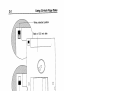
Using 3.S-lnch Floppy Disks .......................................................... C-1
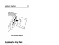
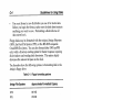
Guidelines for Using Disks ............................................................ C-3
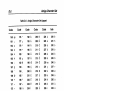
AppendixD
Amiga Character Set
Index
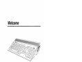
Welcome
The hardware strengths ofthe Commodore® Amiga® family cif
personal computers make the Amiga the computer platform of
choice for video, multimedia, 3-D mode ling, animation, and other
graphics-intensive applications. The Amiga 1200 line features more
sophisticated standard graphics capabilities and a compact,
expandable base unit for maximum flexibility.
Features
The Amiga 1200 (A1200) offers a set of advanced features,
including:
•
•
•
•
Motorola 68EC020 microprocessor running at 14 MHz
Factory-installed Motorola Floating Point Unit (FPU) available
AA custom chipset offering graphics with 256 colors from a
palette of 16.8 million in all color modes
Built-in de-interlacing ofNTSC and PAL video modes
x
•
•
•
•
•
•
•
•
•
•
Using this Guide
Up to 2 megabytes 32-bit "Chip" memory
IDE (16-bit) hard drive interface
Optional internaI2.5-inch hard drive
Integral full-size keyboard with numeric keypad
PCMCIA "credit card" memory/accessory slot
Internal 150-pin "local bus" CPU slot
Expandable to 8 megabytes "Fast" memory
RGB, color composite, and RF (television) outputs
Built-in 880 KB floppy disk drive
Four-voice stereo sound output
Using this Guide
This guide is designed to help you set up your Amiga system quickly
and safely. It contains information on making the necessary
external connections, adding internal and external expansion
options, and other hardware-related tasks. Once your Amiga
system is up and running properly, you should be able to put this
manual aside until such time as you add expansion hardware or
need technical information.
Consult the other Amiga documentation included with your system
for software information.
DocumentConvenHons
In this and other Amiga documentation from Commodore, the
following conventions are used:
Amiga, A1200 The Amiga 1200 main unit is usually referred to as
the A1200 or the Amiga.
Key1 + Key2
Key combinations with a plus (+) sign between the
keys indicate pressing the keys simultaneously. For
example, Right Amiga+O means to hold down the
rIght Amiga key and, while holding it down, press O.
Related Documentation
xi
Amigakeys
These two keys on the Amiga keyboard are used for
special functions. The left Amiga key is to the left of
the space bar and is marked with a large solid A.
The right Amiga key is to the right of the space bar
and is marked with an outlined A. Unlike Shift and
Alt key pairs, the two Amiga keys usually have
different functions.
Enter
Directions to "enter" something mean to type in the
indicated information and then press Return.
arrow keys
The arrow keys are the four keys in an inverted-T
formation to the right of the main keyboard, with
arrows on them pointing up, down, left, and right.
Do not confuse these keys with others on the
keyboard marked with arrows.
Related Documentation
•
Workbench™
•
AmigaDOSTM User's Guide
•
ARexx User's Guide
The Amiga Hard Drive User's Guide
•
User's Guide
If you come upon terms in this book that you do not understand,
look in the Glossary of the Workbench User's Guide, which defines
many computer and Amiga-specific terms.
1
1
1
1
1
1
1
1
1
1
1
1
1
1
1
1
1
1
1
Chapter 1
Quick Connect
As you unpack your system, check the items in the system box.
Contact your dealer immediately if anything is damaged.
This chapter guides you through setting up your system. Read the
instructions carefully.
Before You Begin
•
•
•
•
•
Choose a location for your system away from heat, dust, smoke,
vibration and electrical interference.
Choose a stable work surface at least 6 in.l15 cm away from a
wall.
Have on hand a multi-outlet power strip with surge protection.
(These units are available from most computer stores.)
Commodore strongly recommends that you use this type of
outlet to protect your system from electrical problems.
Make sure your equipment matches the electrical requirements
for the country in which you are using the computer. For
example, you can't use a 110/115 volt model in countries having
a 220/240 volt system.
Read the descriptions in this chapter to acquaint yourself with
the purpose and function of each feature and connector.
As You Set Up Your System
•
If possible, plug your system into a separate circuit to avoid any
electrical interference. Voltage surges and drops caused by
Main Unit
1-2
•
•
•
•
devices such as air conditioners, fans and vacuum cleaners can
cause damage to your computer data and/or to the computer
itself.
Look at your system and match the features and connectors
with the illustrations in this chapter. Use the illustrations to
help you identify the lights, switches, connectors and disk drive.
Use the instructions to connect the monitor, mouse, and any
optional peripherals to the system unit. All connectors are
shaped so they fit only one way. Don't try to force a cable into a
connector.
Never connect or disconnect any equipment when the system
power is on!
If you have a problem, always check the instructions before
proceeding, especially the illustrations. Remember, you can
cause damage by not following instructions.
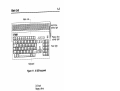
Main Unit
The main unit case contains the basic components that run your
computer. The system motherboard, disk drives, and optional
expansion module are located in the main unit. Most other parts of
your computer system connect to the main unit by cables.
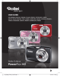
The top panel, illustrated in Figure 1-1, identifies system features
such as the keyboard and disk drive activity lights.
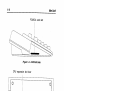
The right side panel, illustrated in Figure 1-2, shows the floppy
drive slot and disk eject button.
The left side panel, illustrated in Figure 1-3, shows the PCMCIA
card slot.
The bottom panel, illustrated in Figure 1-4, shows the location of
the CPU expansion slot door.
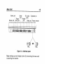
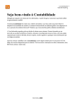
The rear panel, illustrated in Figure 1-5, shows you where the other
parts of your system (for example, the monitor and mouse) plug into
the main unit.
1-3
Main Unit
Main unit
Hard drive
activity light
--+-rt-- Floppy drive
activity light
Keyboard
Figure 1-1. A 1200 top panel
3.5-inch
floppy drive
~
Disk eject button
Figure 1-2. A1200 right side
1-4
Main Unit
PCMCIA card slot
Figure 1-3. A 1200 left side
CPU expansion slot door
0
0
--
I-I--
@
@
L-
r-
0
0
-IOJ-
J(jI11mm11l1l1mHR11
Figure 1-4. A 1200 bottom
111111111801
0
1-5
Main Unit
Game port
Mouse port
Serial
port
Floppy
drive port
R/L Audio
jacks
Parallel
port
Composite jack
Video port
Power con nector
!
\
l
e
"
Cl ~rE1J!li·::'~::~:j"".1
~ !ll.:.~:;.::~;;. Ai9°~
0 "'-~-~ J
~m0
PAL
OR
Cm 0
NTSC
Figure 1-5. A 1200 rear panel
Begin setting up your Amiga system by connecting the mouse and
connecting. the monitor.
Attaching the Mouse
~
To attach the mouse, plug the mouse cable into the port
labeled MOUSE on the rear of the Amiga. Press firmly, but
do not force. The cable connector is designed to fit snugly
into the mouse port.
Leave a clear area approximately 12 inches (30 centimeters) square
to the right or the left of the Amiga so that you have room to move
the mouse freely. Use ofa mouse pad helps keep the mouse from
getting dirty and makes it respond better.
Before using the mouse, remove the packing
material. Turn the mouse upside down and pull
out the foam strip that holds the mouse ball in
place.
Main Unit
1-6
Attaching a Monitor
The A1200 has three display outputs, allowing you to use any of
several kinds of display devices:
•
•
VIDEO port: analog RGB monitor (multiscanl15 KHzNGA);
television with SCART connection
COMP. jack: composite monitor; television (using VCR video
input)
RF MODULATOR jack: NTSC television; PAL television
See the documentation for your monitor and any other graphics
expansion hardware you may have for specific information about
making the proper connections. Appendix A has more information
on monitor compatibility. Your dealer can help you choose the right
combination of graphics hardware, monitor, and monitor cable or
adapter for your use.
After connecting your monitor, skip ahead to the section
"Connecting Power and Turning On the Amiga" if you have no
optional equipment to install. Power connection is always the final
step.
RGB Monitors
An RGB monitor gives the highest quality picture, and allows you
the widest selection of the Amiga's many display modes.
Several types of analog RGB monitors can be used with the A1200,
including multiscan, 15 KHz, and VGAlSVGA monitors. A
multiscan (multiple horizontal scan rate or "multisync") RGB
monitor provides the greatest flexibility. A multiscan monitor is
required if you wish to use display modes that have different
horizontal scan rates.
A 15 KHz analog RGB monitor can display only the
Amiga's default display mode and other 15 KHz scan rate
modes. A VGA or SVGA type monitor can display the
Amiga's de-interlaced and higher resolution modes, but
not the standard 15 KHz video modes.
Main Unit
1-7
Connect a 15 KHz monitor with a 23-pin female connector,
such as the Commodore 1084 or 10848, directly to the
A1200 VIDEO port. For a monitor such as a multiscan,
VGA, or 8VGA model that has a small 15-pin VGA-style
connector, connect the 23-pin to 15-pin adapter included
with the A1200 to the VIDEO port, then connect the
monitor cable to the adapter.
With the proper adapter cable, a television with a SCART input can
be used as a 15 KHz RGB monitor. See the "SCART Televisions"
section below for more information.
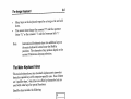
Composite Monitors
o Use
a connector cable with a male RCA-type plug at one end
and a plug compatible with your monitor input to connect a
~
composite monitor. Plug the RCA end into the Amiga's
composite output jack (labelled COMP.) and the other end into
the composite input jack on the monitor.
You can also plug this end of the cable into a VCR that has a
composite input (usually an RCA-type jack labeled VIDEO IN
or EXTERNAL VIDEO). This allows you to record Amiga output
onto video cassette and use a television connected to the VCR for the
Amiga display.
This method provides a higher quality picture than using the RF
modulator output to connect to the VCR or television antenna
inputs. However, only the standard 15 KHz display modes can be
displayed this way. An RGB monitor is required to properly
reproduce the Amiga's de-interlaced and higher resolution display
modes.
NTSC Televisions
Connecting an NTSC television requires a computerlTV switch box
and a connector cable with male RCA-type plugs at both ends. If
your television reception is through a coaxial cable with a round "F"
connector you also need a 75-ohm to 300-ohm adapter. These items
are available from any department or electronics store.
1-8
Main Unit
If you have a VCR or television set with a composite video input (an
RCAjack usually labeled VID~O IN) you should use the composite
output as described in the "Composite Monitors" section above. This
is simpler and produces a better picture. If your TV or VCR has
antenna inputs only, use the following procedure:
1.
Disconnect the cable or VHF antenna wire from the TV or VCR.
2. For coaxial cable: connect the end of the cable to a 75-ohm to
300-ohm adapter.
3.
Connect the VHF antenna or adapter leads to the CONNECT
TO ANTENNA terminals on the switch box.
4.
Connect the short twin-lead wire on the side of the switch box to
the VHF terminals on the TV or VCR.
5.
Plug one end of the connector cable into the RF MODULATOR
jack on the Amiga.
6.
Plug the other end of the connector cable into the COMPUTER
jack on the switch box.
Channel
select switch
I ,- RF modulator
~jaCk
'"
I
~o
,(C! I';:
{~
300-ohm
~
'---~_ _0----' ~
Switch box
OR
~ m=t=
Adapter
7S-ohm
7.
Set the Channel Select switch to the left for channel 3 or to the
right for channel 4, whichever is not used in your geographical
area.
8.
Select the COMPUTER switch setting on the switch box.
1-9
Main Unit
Audio output from the Amiga will use the televis ion's speake r(s).
You may also connec t the Amiga audio output s as describ ed in the
"Audio Conne ction" section .
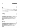
PAL Televisions
If you have a PAL VCR or televis ion set with a SCART input, see
a
the "SCAR T Televisions" section below. If your TV or VCR has
should
you
IN)
compo site video input (a jack usuall y labeled VIDEO
use the COMP . output as describ ed in the "Composite Monitors"
a
section above. Either of these metho ds is simple r and produc es
.
output
better picture than using the RF MODU LATO R
a
Conne cting a PAL televis ion with only an antenn a input requir es
a
and
end
one
at
plug
ype
RCA-t
male
connec tor cable with a
standa rd 75-0hm PAL connec tor at the other end. Use the
follow ing proced ure:
Video tuning screw 1. Insert the PAL end of the connec tor
cable in the 75-0hm antenn a jack on
Audio switch
the TV.
~
@jm.
~
RF modulator jack
®
ll:::====r:!=ill] I I
2. Insert the RCA-t ype end of the cable
in the RF MODU LATO R jack on the
Amiga .
3. Plug in and turn on the Amiga (see
the section "Connecting Power and
Turnin g On the Amiga ").
Turn on the TV and tune it to channe l 36.
5. U se a small flat-bla de screwd river to turn the A1200 Video
Tunin g screw near the RF MODU LATO R jack until the picture
is clear and stable.
6. Run some softwa re that produc es sound, such as a game.
ver
7. Set the PAL Audio switch to the left or right positio n, whiche
gives the best sound.
8. Turn off the Amiga and discon nect it from power if you have
any other equipm ent to connec t.
4.
Connecting Optional Equipment
1-10
Audio output from the Amiga will use the television's speaker(s).
You may also connect the Amiga audio outputs as described in the
"Audio Connection" section.
SCART Televisions
Use a SCARTIRGB adapter cable to connect the Amiga to
equipment with a SCART connector. Insert the 23-pin end of the
cable into the VIDEO port on the Amiga and the RCA plugs into the
left and right Amiga audio jacks. Insert the SCART connector on
the other end of the cable into the connector on the equipment.
Audio output from the Amiga will use the television's speaker(s) ..
You may also connect the Amiga audio outputs as described in the
"Audio Connection" section.
Note
Since the definition of the SCART interface varies
somewhat among TV manufacturers, consult an
electronics or computer dealer to get the proper
SCART adapter cable for your TV.
Connecting Optional Equipment
If you have tested your Amiga system after making the basic
connections, turn it off before connecting any other items. Never
attempt to connect or disconnect anything while the power is on.
Audio Connection
Two RCAjacks (female connectors) labeled R. AUDIO and
L. AUDIO connect the Amiga's left and right sound
channels to a monitor or audio equipment. You need to
connect these to hear sound from your Amiga unless you
are using an RF connection to a TV or VCR.
Connecting Optional Equipment
1-11
Audio Connection to a Stereo Monitor
A monito r with intern al speake rs allows you to hear the Amiga 's
sound output withou t other extern al equipm ent. An Amiga stereo
monito r comes with a stereo cable, col or-coded for the left and right
channe ls. Insert the connec tors at one end of the cflble into the
Amiga 's left and right audio output jacks. Then insert the cable's
other connec tors into the corresp onding audio input jacks on the
monito r.
Audio Connection to a Monaural Monitor
A monito r with monau ral sound capabi lity can still accept both
Amiga audio channe ls. Either use a "Y" adapte r cable plugge d into
one
both Amiga audio jacks, or plug a single audio cable into either
r's
monito
the
into
cable
the
of the jacks. Insert the other end of
r
audio input jack. Both audio channe ls will be routed to the monito
speake r.
Audio Connection to Other Equipment
's
If your monito r does not have speake rs, you can connec t the Amiga
or
,
system
audio output to separa te powere d speake rs, a stereo
other audio equipm ent. Use input connec tors labeled Auxili ary,
Aux, Audio In, CD, Tape, VCR Audio, etc. on the equipm ent. You
need a stereo audio cable with RCA connec tors at one end and the
approp riate type of connec tor for your equipm ent at the other end.
Audio cables and adapte rs are availab le from most electro nics and
stereo stores.
Insert the RCA connec tors into the Amiga 's audio output jacks and
the other connec tors into the equipm ent's corres pondin g audio input
jacks. Consu lt the equipm ent's user manua l for furthe r instruc tions
on using its extern al inputs .
1-12
Connecting Optional Equipment
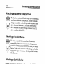
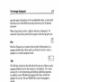
Attaching an External Floppy Drive
To attach an extern a13.5- inch floppy drive to the Amiga ,
use the port labeled DISK DRIVE . The drive must be
Amiga compa tible, with a 23-pin male connec tor. This
drive becom es device DFl:. A second extern al floppy
drive attach ed to a pass-th rough connec tor on a DFl:
drive would be device DF2:.
Attaching a Parallel Device
I~I To attach a paralle l device such as a Centro nics
compa tible printe r or a scanne r to the Amiga , use the
port labeled PARA LLEL PORT. The cable you use must
have a 25-pin male connec tor on the Amiga end and the
approp riate type of connec tor for the paralle l device on
the other end.
g
Attaching a Serial Device
~
¥
==
To attach a serial device, such as a modem , MIDI
interfa ce, or serial printer , use the port labeled SERIA L
PORT. The cable you use must have a 25-pin female
connec tor on the Amiga end and the approp riate type of
connec tor for the serial device on the other end.
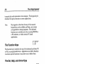
Attaching a Joystick
~
Note
To attach a joystic k, light pen, or other specia l contro ller, use
the 9-pin port labeled GAME on the rear of the unit. The
contro ller's connec tor must be female .
Refer to Appen dix B for techni cal inform ation on the
extern al connec tors.
Connecting Power and Turning On the Amiga
1-13
Connecting Power and Turning On
the Amiga
Caution
Do not plug in and turn on the Amiga until you have
securely connected all equipment.
When all other connections have been made, you can connect your
system to power and turn it on.
1.
Connect peripherals to power.
2.
Plug in all peripheral equipment as described in the previous
sections.
3.
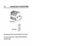
Attach the Amiga power cable.
In the United States and Canada the Amiga power cable has a
square 5-pin male connector at one end, the power supply in the
middle, and a standard 3-prong male power plug on the other
end.
Note
Different countries may use other power cable
designs. Be sure your Amiga matches the electrical
voltage requirements in your country.
Attach the male end to the connector labeled POWER on the
rear of the A1200. The other end of the cable may then be
inserted into a three-prong grounded AC outlet. The power
switch is on the power supply.
If in doubt about electrical hookup requirements consult your
dealer.
4.
Plug in the Amiga.
5.
Turn on the other equipment.
6.
Turn on the Amiga
1-14
Connecting Power and Turning On the Amiga
Power switch
--I
Switch the power switch on the power supply to the on (I) position.
The Amiga will begin to boot. Chapter 2 contains information on
booting the Amiga.
Chapter 2
Getting Started
This chapter covers booting your Amiga system for the first time,
using the keyboard, and using keyboard mouse equivalents.
Booting Floppy-Based Systems
When an Amiga system is turned on, it looks for a bootable floppy
disk in the internal floppy drive, DFO:. This disk can be a copy of
your Workbench disk or a bootable application disk.
If a bootable disk is not found, a floppy-based Amiga (no hard drive)
prompts you by showing a screen with a disk being inserted into a
drive. When a bootable floppy disk is inserted into DFO:, the screen
goes blank while the Amiga loads the system information it needs
from the disk.
Booting from floppy takes about two minutes. When the process is
complete, you should see a screen similar to that illustrated in
Figure 2-1.
Booting Hard Disk-Based Systems
The Amiga can boot directly from a hard disk if your system has
one. You do not need to insert any floppy disks. Hard disk users
may boot from floppy, however, by inserting a bootable disk in DFO:
before rebooting or turning the Amiga on.
Booting from hard disk generally takes about 30 seconds. When the
process is complete, you should see a screen similar to that
illustrated in Figure 2-1.
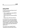
The Opening Screen
2-2
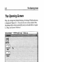
The Opening Screen
When the Amiga has finished booting, the Amiga Workbench screen
is displayed (Figure 2-1). If you do not see a screen similar to this,
the Amiga did not boot successfully and you should refer to Chapter
5, "Help with System Problems. "
Figure 2-1. Workbench screen
With the Workbench screen displayed, you can set up the
Workbench environment as it suits you and configure the system to
take best advantage of your hardware setup.
See the Workbench User's Guide for complete information on:
•
•
•
•
•
Booting and rebooting
Installing and reinstalling the system software
Setting the system up for your keyboard, language, and country
Making backup copies of your system disks
U sing the Preferences editors
Turning Off the Amiga
2-3
The rest of this guide assumes that you are familiar with basic
Amiga operations and terminology.
Turning Off the Amiga
When you finish a computing session and want to turn off the
Amiga:
1.
Save to disk any work that you want to keep. Turning off or
rebooting the Amiga erases whatever is in memory.
Important: Do not turn off or reboot the Amiga while any disk
activity is in progress! Wait at least 5 seconds after all disk
drive activity lights have gone out before removing floppy disks
or turning off the Amiga. Also, if you are using software that
automatically saves to disk periodically or which allows remote
access to the Amiga's disks through a network, exit the software
or disable the network connection before powering off or
rebooting.
2.
Remove any disks from the floppy drive(s).
3.
Switch the power switch on the side of the power supply to the
off(O) position. The power light on the right front of the Amiga
will go out.
4.
Turn offthe monitor and any peripherals.
Note
If you want to turn the Amiga on again immediately,
wait at least 30 seconds after turning the machine off
before turning it on again.
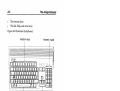
The Amiga Keyboard
The Amiga keyboard is similar to industry-standard computer
keyboards. It has four sections:
•
•
The main keyboard
The numeric keypad
2-4
•
•
The Amiga Keyboard
The function keys
The Del, Help, and arrow keys
Figure 2-2 illustrates the keyboard.
Function keys
Numeric key pad
c:::.::.................
~:;:::;::::::~~::::::
._." ..,-"""
=
::::~::::::~:~::..."::::::' .:=::-~:::::::::::=:~==~=::::::::::::::::::::::--~::::::::::::::::::::::.
c::=
,~,-~",,,----,,,-,-,,,,,--,-
~
- - ' ' ' - - " - - ' ' - - , , , ' ' , ' - , - , - , - ' ' ' ' - - ' ' ' ' - , - - f-----,
~
btt±±±dh!~L_
11 II1 II1 II1 II1 II1 II1 II1 II1 II1 II1 II1 II1 II1
::;
JII II1 II1 II1 11/ II1 II1 II1 11/ II1 III II1 II1
11':l11111111111111111111111111111111IIIIIm
Co
1I III III III III III III III III III III 11 '01IliA 1111
I" JIL"
J
"",.~ ---,
:~
:&b
j
:
4-!....
1ft
1ft
IH
I
I
0"
~I
III
I
IH
1"",1'
JII : '--y--J
~,,- - - - - - - - - - -- - - - t -- - -- - -- - - -- - - - - -- -,
i
i!t::=j!/;;;j/l:;j!/
'"
I
Main keyboard
I
Arrow keypad, Del and Help
Figure 2-2. Amiga keyboard
Remember the following points when using the keyboard:
•
•
•
The layout or "mapping" of characters to the keys is determined
by the Preferences keymap setting. This typically varies by
country.
Keys can be redefined by an application to have special
functions. If you notice unexpected responses to some
keystrokes (especially when switching between windows and
screens running different applications) this may be the reason.
For specifics on how an application affects the keyboard, see the
application's manual.
Depending on the application, certain key combinations may
have special meaning. The keys may need to be pressed
simultaneously or one after the otlier.
The Amiga Keyboard
•
•
2-5
Many keys on the keyboa rd repeat for as long as they are held
down.
You cannot interch ange the numer al "0" and the upperc ase
letter "0," or the numer al "1" and the lowerc ase letter "l."
Note
Intern ationa l keyboa rds have two additio nal keys on
the main keyboa rd, located near the Shift key
positio ns. The charac ters they produc e depend on the
curren t Prefer ences keyma p selecti on.
The Main Keyboard Area
The main keyboa rd area has standa rd alphan umeric typew riter
keys plus special keys with compu ter-spe cific uses. Some of these
are "qualif ier keys," which have no effect by themse lves, but are
used with other keys for specia l functio ns.
Qualif ier keys includ e the following:
Shift Keys
Two Shift keys, marke d with an up arrow (if) are located on either
side of the bottom row of letters . These keys can be used the same
way as the shift keys on a standa rd typewr iter. Press either Shift
key simult aneous ly with any alphab etic key or with any key having
two charac ters on the keycap to produc e the upperc ase or top
charac ter. The Shift keys are also often used with other keys to
perfor m special functio ns.
AIt Keys
The two Alt (Altern ate) keys, located at the extrem e left and right
sides of the bottom row of the keyboa rd, are often used with other
keys to perfor m special functio ns.
2-6
The Amiga Keyboard
Ctrl
The Ctrl (Control) key, located on the left side of the middle row of
letters, is a program-defined key that is often used with other keys
to perform special functions.
Left Amiga
The left Amiga key, located on the bottom row of the keyboard just
to the left of the space bar, is used with other keys to perform
special functions, particularly keyboard shortcuts for gadget
selection.
Right Amiga
The right Amiga key, located on the bottom row of the keyboard just
to the right of the space bar, is used with other keys to perform
special functions, particularly keyboard shortcuts for menu
selection.
Caution
The key combination Ctrl+Left Amiga+Right Amiga
reboots the Amiga. See Chapter 1 in the Workbench
User's Guide for details.
Other special keys include the following:
Return
The Return key, located on the right side of the main
keyboard area in the middle two rows, transmits information or a
command to the computer. This key is sometimes referred to by the
symbol ".J" or as the Enter key.
Caps Lock
[Qffi
~
The Caps Lock key, located next to the Ctrl key, forces all
alphabetic keys (A through Z) to produce uppercase (capital) letters.
Other keys, however, are not affected by the Caps Lock key. To
The Amiga Keyboard
2-7
type the upper characters on the nonalphabetic keys, you must still
hold down one of the Shift keys and press the key for the desired
character.
When Caps Lock is active, a light on the key is illuminated. To
inactivate Caps Lock, press the key again so that its light goes out.
Esc
The Esc (Escape) key, located at the top left of the keyboard, is a
program-defined key, often used as a shortcut to leave or enter a
program or a certain program mode.
Tab
II
The Tab key, located on the left side of the top row ofletters, can be
program-defined to move the cursor to a set position. Tab is used
extensively in word processing and desktop publishing programs.
In addition, many Workbench programs that have several text
gadgets let you use Tab and Shift+ Tab to move from gadget to
gadget.
Backspace
The Backspace key is the key farthest right in the top row of the
main keyboard. Pressing Backspace deletes any characters to the
left of the cursor and causes the cursor, and any characters to the
right of it, to move to the left.
The Numeric Keypad
The numeric keypad is located to the far right of the keyboard. The
keys are arranged in a calculator layout to facilitate numeric data
entry. The numeric and arithmetic symbol keys on the keypad are
equivalent to the numeric and arithmetic symbol keys on the main
keyboard.
In many cases, you can use the Enter key on the numeric keypad
just as you use the Return key on the main keyboard-that is, to
2-8
The Amiga Keyboard
transmit data and commands to the computer. The keypad may be
redefined for special functions oy some applications.
Note
The legends on the front of many of the numeric
keypad keys, such as PgDn and Home, are normally
not applicable to Amiga programs. The indicated
functions are available only when running MS-DOS on
a PC emulator, or within certain PC-based
applications.
The Function Keys
The function keys, located at the top of the keyboard and labeled Fl
to F10, are programmable keys. Applications can define these keys
to activate special functions or may allow you to define them.
The Del, Help, and Arrow Keys
Del
The Del (Delete) key, located just to the right ofthe top row ofthe
main keyboard, deletes the character at the cursor position. Any
characters to the right of the cursor move to the left.
Help
The Help key, located to the right of the Del key, is a programdefined key that applications can use to provide additional
information or user assistance while a program is running.
The Arrow Keypad
The four arrow keys are grouped in a small keypad at
. the lower right side 'of the keyboard, between the main keyboard
and the numeric keypad. These keys control the movement of the
cursor (up, down, left, and right) on the screen. The direction in
which each key moves the cursor is indicated by the direction of the
2-9
The Amiga Keyboard
arrow on the key. These keys may also have special functions with
different qualifier keys, depending on the application.
Keyboard Equivalents to the Mouse
You can use the keyboard in addition to or instead of the mouse to
move around the screen and select icons, gadgets, and windows. In
programs that mainly use the keyboard to enter information, this
can be faster and more convenient.
The keyboard equivalents are especially useful if your mouse is
malfunctioning, or when you need to make extremely precise
pointer movements.
The following key combinations are available from any application,
to let you perform mouse movement and button presses with the
keyboard.
Move left
either Amiga key+left arrow
Move right
either Amiga keYHight arrow
Move up
either Amiga key+up arrow
Move down
either Amiga key+down arrow
Left mouse button
Left Alt+left Amiga
Right mouse button
Right AltHight Amiga
Note
In the arrow key combinations in this table, pressing
Shift at the same time as the other two keys makes the
pointer move faster.
1
1
1
1
1
1
1
1
1
1
1
1
1
1
1
1
Chapter 3
Before Expanding Your
System
This chapter summarizes the expansion options for the Amiga other
than peripherals connected to the rear panel ports. In all cases, see
the installation manual for the option you are installing for detailed
information on how to install it.
The A1200 can accommodate several types of expansion options:
•
•
Memory expansion
Drive expansion
CPU expansion
PCMCIA expansion
Memory Expansion
The amount of random access memory (RAM) in the A1200 is
expandable to 10 megabytes (10 MB). All RAM automatically
configures and is directly addressable by the operating system.
The Amiga's memory consists of Chip RAM and Fast RAM. Chip
RAM is memory shared by the microprocessor and the Amiga's
custom chips. Fast RAM is memory used exclusively by the
processor. The A1200 can use up to 2 MB of Chip RAM and 8 MB of
Fast RAM.
Chip RAM on 1 MB machines can be expanded to 2 MB of 32-bit
memory with an internal expansion module. (This expansion
module can also contain a battery-backed clock/calendar.)
3-2
Drive Expansion
Up to 4 MB of 32-bit Fast RAM can be added using the CPU slot. (A
CPU slot board containing its own microprocessor, such as a 68030
accelerator, could contain more than 4 MB of Fast RAM.) An
additional 4 MB of 16-bit memory can be added using the PCMCIA
memory card slot.
Drive Expansion
The AI200 can accommodate a 2.5-inch hard drive internally. The
AI200 contains a built-in Intelligent Drive Electronics (IDE) hard
disk controller, to which the hard drive may be connected.
External storage devices such as a CD-ROM, tape, or hard drives
may be added using the PCMCIA slot. (An external drive may
require a controller, such as a SCSI adapter, in addition to the drive
itself.)
CPU ExpanSion
The I50-pin CPU slot accessible through the door in the bottom of
the AI200 can accommodate various types of expansion. This can
include accelerator boards, additional RAM, PC emulators, and
other options that must have direct access to the Amiga's internal
hardware.
PCMCIA Expansion
The PCMCIA "credit card" slot is a standard, general purpose
expansion connector. It allows you to use a wide range of expansion
options, such as additional system RAM, modems, ROM card
applications, networking hardware, SCSI adapters, and so on as
they become available for compact computers from various
manufacturers. These options can be connected and disconnected
easily, without the need to open the computer. Only one PCMCIA
expansion item at a time can be used.
The next chapter contains details on PCMCIA expansion.
When Installing Internal Options
3-3
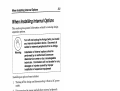
When Installing Internal Options
This section gives genera l inform ation related to install ing Amiga
expans ion option s.
Turn off and unplug the Amiga before you install
any internal expansion device. Disconnect all
cables for external peripherals from the Amiga.
Warning
Installation of internal options should be
performed by an authorized Commodore
dealer/service center or by a knowledgeable
technician. Commodore will not be liable for any
damages or injuries caused by improper
installation of expansion equipment.
Install ing an option always include s:
Turnin g off the Amiga and discon necting it from the AC power
outlet.
2. Discon necting the mouse and all other extern al periph erals.
3. Follow ing the expans ion device manuf acture r's specifi c
install ation instruc tions.
re
4. Recon nectin g periph erals and power, perfor ming any softwa
testing
and
ary,
necess
be
install ation or config uration that may
the device for proper operat ion.
1.
Note
Becau se option al items can occasio nally have
unfore seen interac tions, Comm odore strong ly
recom mends that new expans ion device s be tested first
. withou t any other expans ion device s connec ted. If you
experi ence proble ms after install ing any device, try
remov ing any other option al items from the system ,
and test the new item by itself, then in variou s
combin ations with other items. Often a solutio n to the
proble m can be found when the interac ting items are
identif ied.
3-4
When Installing Internal Options
ESD Precautions
Integrated circuit (IC) chips are sensitive to static electricity. When
handling electronic components containing IC chips, including
expansion boards and RAM modules, always take precautions to
reduce the chances of electrostatic discharge (ESD) harming the
components.
Touching a nearby grounded metal surface before touching a
component drains static electricity, reducing the likelihood of ESD
damage.
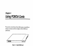
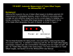
Chapter 4
Using PCMCIA Cards
The card slot in the left side of the A1200 accepts a standard 68-pin
memory or accessory card that complies with the PCMCIA 2.0
specification.
Figure 4-1. Typical PCMCIA card
Although any PCMCIA 2.0 compliant products should work
properly together, some cards and accessories may be designed with
a particular type of computer in mind. You should check with your
Amiga dealer to help you determine whether a certain item will
work as expected.
Inserting and Removing Card Slot
Devices
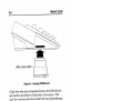
To use a memory card or a card slot accessory, insert the edge of the
connector that has the row of small holes into the slot in the left side
of the Amiga, as illustrated in Figure 4-2. A memory card's label
should be facing up. Only about 1 inch/3 cm of the card or accessory
connector enters the slot. Insert it firmly, but do not use excessive
force-it does not click into place.
4-2
Memory Cards
Write protect switch
-i--------,
Figure 4-2. Inserting PCMCIA card
Unlike with other types of expansion devices, the A1200 allows the
safe insertion and removal of cards while it is turned on. While
such "live" insertion and removal should not cause physical damage,
some caution must be taken. Removing a card or card slot accessory
that is in use will interrupt its operation and almost certainly will
produce undesired or unexpected results, as noted in this chapter's
final section.
Memory Cards
Memory cards can function as expansion RAM or as disk-like
storage devices. You use the PrepCard utility, described in Chapter
10 of the Workbench User's Guide, to prepare memory cards for use
either as RAM or as a "card disk."
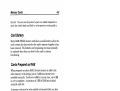
Write-Protection
Like floppy disks, memory cards can be write-protected. There is a
small switch on the edge of the card opposite the end that goes into
Memory Cards
4-3
the slot. You can use the point of a pen or a similar implement to
move the switch back and forth to write-protect or write-enable it.
Card Battery
Static RAM (SRAM) memory cards have a small battery to allow the
card to retain the data stored in the card's memory chips after it has
been removed. The batteries are long-lasting, but must eventually
be replaced when they run down for the card to continue
functioning.
Cards Prepared as RAM
When prepared as system RAM, the card memory is added to the
other memory in the Amiga, just as if additional memory were .
installed internally. Cards are available in many sizes, from 64 KB
to over a megabyte. A maximum of 4 MB of RAM may be added
using the card slot.
A memory card must be write-enabled and inserted before you boot
or reboot for its memory to be added to the Amiga's RAM. Card
memory is added to Fast memory. The total number of bytes of
available Fast RAM is shown in the Workbench screen title bar as
"other mem".
Cards Prepared as Disk
A card disk is used much as a floppy disk is used: you can read from
and write to the card as you normally do, from applications, the
Workbench, or the Shell. The contents of the card remain even
when you remove the card or turn off the Amiga. Read and write
operations using memory cards are very fast.
You can insert and remove the card while the Amiga is turned on.
However, wait a few seconds after attempting any card disk access
before you remove the card, to be sure the disk activity has finished.
4-4
ROM Applications
ROM Applications
Games or other applications may be available on PCMCIA ROM
cards. To be usable on the A1200, the application must be written
specifically for the Amiga. A PCMCIA ROM application may "take
over" the Amiga, preventing multitasking (running the Workbench,
or other applications). See the ROM card's documentation for more
information.
Other Devices
Accessories, such as modems or network adapters having a
PCMCIA connector, can also be attached with the card slot.
Directions on use of these items will be included with the device.
Notes on Insertion and Removal
•
•
•
•
•
•
Only one memory card or accessory may be inserted at a time.
Removing a ROM application card or a memory card that is
currently in use as RAM immediately reboots the Amiga.
Do not write-protect a memory card while it is in use as RAMthis causes the Amiga to lock up, requiring you to reboot.
Do not remove a card disk immediately after attempting an
open or save operation on it.
Removing an accessory such as a modem or network adapter
while it is operating immediately breaks its communication
connection.
Removing an accessory, such as a SCSI adapter, that connects
to storage devices while it is operating may cause a disk error,
damaging files or directory structures on the associated storage
devices.
ChapterS
Help With System Problems
If you have a problem with your Amiga or experience unexpected
results, there may be an easy solution. Many problems result from
simple errors in setting up the system or installing expansion
devices.
Caution
Commodore will not be held liable for damages or
injuries resulting from improper installation or
repairs attempted by unauthorized personnel.
Although you can solve many problems yourself, others result from
hardware failure and require the assistance of your Commodore
dealer/service center or a knowledgeable technician. Never attempt
to repair any problem involving internal damage to the Amiga
yourself.
A voiding Problems
The three most important rules to remember to prevent damage to
your computer, files, and disks are:
1. Never connect or disconnect anything while the power is on!
This applies to internal and external connectors other than the
PCMCIA slot, including the mouse and game controllers. It is
very easy to cause damage that requires a service call by
connecting or disconnecting something without first turning the
system oft'.
Identifying and Solving Problems
5-2
2. Never interrupt disk activity!
This applies to floppy disks, hard disks, and PCMCIA card
disks. When floppy or hard disk activity is in progress, the
drive activity light on the top of the computer is lit. (There is no
drive activity light for a card disk.) Interrupting disk activity
(by removing a disk from its drive, rebooting, or powering off)
can cause disk errors. Always wait a few seconds after the drive
activity lights seem to have stopped, to be sure all disk activity
has finished.
3.
Read the documentation!
The vast majority. of problems can be avoided by carefully
reading and following the instructions for the hardware and
software you use.
Identifying and Solving Problems
There are several general types of problems that can appear when
you use your system:
Software problems
•
•
•
Startup problems
Disk problems
Installation and maintenance problems
Software Problems
This chapter focuses on hardware problems and their possible
solutions. For information on software-related problems, consult
your Amiga software documentation.
Typical software problems include:
•
•
•
Preferences settings for your language, country, and national
keyboard type (keymap) have not been made yet.
Preferences settings do not match your peripheral hardware,
such as modem or printer.
New software was improperly installed.
Identifying and Solving Problems
•
•
•
•
5-3
Necessary directories or files are missing from the boot volume.
Necessary directory assignments have not been made.
The standard Startup-sequence file has been altered.
There is a disk error.
Problems of this type usually produce requesters or error messages
that give some indication ofthe source of the trouble. Note this
information and consult your Amiga software documentation for
guidance. The Workbench User's Guide and the Amiga Hard Drive
User's Guide have information about software installation, proper
Preferences settings, and the use of programs that can help with
disk problems.
Startup Problems
Problems starting up the system from a power-off state are the most
common sources of confusion for new users. This most often results
from simple mistakes in setting up the system. Actual hardware
failure is a less frequent cause.
Check the following if your Amiga does not respond when you turn
it on:
•
•
•
•
•
•
•
•
•
Is the Amiga plugged in to a power source of the correct voltage?
Is the monitor plugged in to a power source of the correct
voltage?
Is the monitor connected to the Amiga?
Are both the monitor and the Amiga turned on?
If the Amiga is plugged in to a multiple-outlet power strip, is the
power strip plugged in, turned on, and working properly?
Are the monitor and the monitor cable known to work correctly?
Is the monitor of a type capable of displaying the Amiga's video
output?
Is the monitor set to accept the Amiga's default video mode?
Is the monitor securely connected to the main unit?
For information on these basic setup questions, refer to the "About
Electrical Requirements", "Connecting Power and Turning On the
Amiga", and "Attaching the Monitor" sections of Chapter 1. Also see
5-4
Identifying and Solving Problems
the ScreenMode sections in the Workbench User's Guide, and your
monitor manual.
Disk Problems
Notes on Floppy-Based Systems
If the Amiga comes on, but does not boot, check the following before
suspecting a hardware problem:
•
•
•
Did you insert a copy of your Workbench disk when prompted
by the initial animated sequence?
Did you insert the floppy properly into the drive?
Is the Workbench disk you inserted an exact copy of your
original Workbench disk, or a disk you know to be bootable?
If the Amiga will not boot from a given disk, try others that you
know to be bootable. You should always keep your original,
unmodified Workbench disk available in case of such a problem.
If the Amiga will not boot from any floppy, even those you know to
be good, then it is probable that the floppy drive or the computer
itself has some hardware problem.
Notes on Hard Disk Systems
If the Amiga comes on, but does not boot, check the following before
suspecting a hardware problem:
•
•
•
Do you have a bootable hard drive partition in the system?
Is the partition you want to boot from enabled, and does it have
a boot priority above other bootable devices or partitions?
Does your bootable partition have all the required directories
and files available on it?
If you have trouble booting from your hard disk, try booting from
floppy. If you can boot from floppy, then your hard disk setup, or
something on your hard disk, probably is the source of the trouble.
Mter booting from floppy you may still be able to access your hard
disk to try to determine the source of the trouble.
Identifying and Solving Problems
5-5
Typical disk drive hardware problems include:
•
•
•
•
•
•
•
A drive ribbon cable connector is inserted in its drive or
motherboard connector(s) improperly.
A drive is not connected to power, or the power supply is
overloaded.
A drive ID or unit number jumper is set incorrectly.
A drive controller is not fully seated in its slot.
The device chain is not terminated correctly (SCSI drive
systems).
A hard drive takes too long to spin up to working speed.
A drive or controller has the wrong ROM version.
A drive ribbon cable is faulty.
A drive is faulty.
For solutions to these problems, also check:
•
•
•
Sections on disk use in the Workbench User's Guide
The Amiga Hard Drive User's Guide
The drive's user manual
Installation and Maintenance Problems
Installation problems are most likely to appear after you have added
a new drive or other hardware item to the system. If you have a
problem after installing additional hardware, xemove the new item
and see if the problem disappears. Hit does, you know the problem
is in that item or its installation. Repeat the installation, following
the hardware manufacturer's installation instructions carefully.
If you have several expansion devices, the problem may be an
interaction between two or more items that by themselves work
properly. Try running your system with different combinations of
expansion devices to isolate the offending items. If the item
requires its own software, consider different settings the software
may offer.
Non User-Serviceable Problems
5-6
Installation Problems
If the fault is not in the new hardware itself, there may be a
problem with its installation. Check to be sure that:
•
•
•
•
•
A board installed in the CPU slot is fully seated in the slot.
An accessory installed in the PCMCIA slot is fully seated in the
slot.
A PCMCIA memory card is write-enabled when it needs to be.
All jumpers are set properly according to the documentation.
All peripherals were properly reconnected to the Amiga after
installation.
Maintenance Problems
•
•
•
A floppy, removable media, or CD-ROM drive is dirty or out of
alignment. Use a commercial cleaning product according to the
drive manufacturer's directions, or have your dealer/service
center adjust the drive.
The mouse ball or mouse ball rollers are dirty. Open the mouse
ball cavity, remove the ball, and clean the ball and interior with
a cotton swab.
Connector pins are bent or dirty. Carefully clean and straighten
the pins.
Non User-Serviceable Problems
If you still have a problem after trying the remedies suggested here,
you may have a hardware problem that requires professional
attention. Have your Amiga examined by your Amiga dealer/service
center or a knowledgeable technician. If the problem appears to be
with a third-party device, contact its manufacturer.
Do not try to repair a damaged or malfunctioning unit yourself.
This could cause further damage, possible injury, and the voiding of
your warranties.
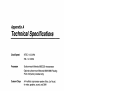
Appendix A
Technical Specifications
Clock Speed
NTSC: 14.32 MHz
PAL: 14.19 MHz
Processor
Surface-mount Motorola 68EC020 microprocessor
Optional surface-mount Motorola 68881/68882 Floating
Point Unit (factory-installed only)
Custom Chips
AA multichip coprocessor system (AI ice, Lisa, Paula)
for video, graphics, sound, and OMA
Fast Memory
Expandable to 4 MB of 32-bit RAM in CPU slot,
additional 4 MB of 16-bit RAM in PCMCIA card slot
Chip Memory
1 MB or 2 MB of 32-bit RAM; second megabyte on
motherboard or on internal expansion module
ROM
512 KB
External
Interfaces
Mouse / Joystick (OB9 male, two)
Serial (OB25 male, RS-232, PC-compatible)
Parallel (OB25 female, Centronics-compatible)
Floppy (OB23 female, standard Amiga)
Memory card (standard 68-pin PCMCIA 2.0)
RGB (OB23 male, analog RGB / digital RGBI / SCART)
Color composite video (RCA, NTSC / PAL)
RF modulator (RCA, NTSC / PAL)
Stereo audio (RCA, two)
Technical Specifications
A-2
Internal
Interfaces
AT IDE (40-pin header)
Keyboard
Integral, 96 keys; international (configurable keymap)
Internal Disk
Drives
One internal 3.5-inch floppy drive standard
(880 KB formatted maximum)
CPU local bus (150-pin edge)
Mounting provisions for one 2.5-inch AT IDE hard drive
External Disk
Drives
Video Display
Up to two compatible floppy drives
Additional drives possible as PC MC lA accessories
Output type: RGB, analog and digital; color composite;
RF modulated; interlaced and non-interlaced; up to 8
bitplanes
Compliance: NTSC and PAL
Color palette: 16.8 million
Horizontal scan rates:* 15.6 KHz to 31.4 KHz
Vertical scan rates:* 50 Hz to 73 Hz
Sound
4 independent voices configured as two stereo
channels
Clock/calendar
Optional, with battery backup
Power Supply
23 watts, switching
Environmental
Specification
Operating: 0 - 45°C (32 - 113°F)
Storage/Shipping: 0 - 60°C (32 - 140°F)
'See the Mode Properties display in the ScreenMode Preferences editor for a given
display mode's exact scan rates. Compare the scan rates of modes you wish to use
and your monitor specifications to help determine monitor compatibility.
AppendixB
Input/Output Connector Pin
Assignments
This section lists pin assignments (pinouts) for input/output
connectors on the Amiga. The information in this section is
technical and is intended only for those with special needs in
connecting external devices to the Amiga. You should not need this
information if you use cables designed specifically for the Amiga and
the peripheral you want to connect.
Caution
Some pins on Amiga connectors provide power
outputs and non-standard signals. Attempting to use
cables not wired specifically for the Amiga may
damage the Amiga or the equipment you connect.
The descriptions that follow include specific warnings for each
connector. For more information about connecting peripherals,
consult your Amiga dealer or service center.
Note
In the descriptions that follow, a forward slash in front
ofthe signal name (for example, ISTROBE) indicates
a signal that is active low.
The I/O (Input/Output) column lists signal types: I for
Input, 0 for Output, OC for Open Collector.
SERIAL Port
8-2
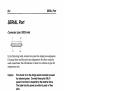
SERIAL Port
Connector type: D825 male
13
14
25
In the following table, column two gives the Arniga pin assignments.
Columns three and four give pin assignments for other commonly
used connections; the information in these two columns is given for
comparison only.
Caution
Pins 9 and 10 on the Amiga serial connector are used
for external power. Connect these pins ONLY if
power from them is required by the external device.
The table lists the power provided by each of these
pins.
Pin 7 is the system ground. Do not connect this to
shield ground on Pin 1.
8-3
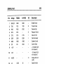
SERIAL Port
1/0
Pin
Amiga
RS232
HAVES
1
SHIELD
GND
GND
2
TXD
TXD
TXD
0
Transmit Data
3
RXD
RXD
RXD
I
Receive Data
4
RTS
RTS
0
Request to Send
5
CTS
CTS
CTS
Clear to Send
6
DSR
DSR
DSR
Data Set Ready
7
GND
GND
GND
System Ground
8
CD
CD
DCD
Carrier Detect
9
+12V
+ 12 Volts DC (20
mA maximum)
10
-12V
-12 Volts DC (20
mA maximum)
11
AUDO
12
13
14
17
n/c
n/c
n/c
n/c
n/c
n/c
18
AUDI
19
20
n/c
S.RTS
DTR
DTR
21
n/c
SOD
22
23
24
RI
RI
n/c
n/c
n/c
TXC1
15
16
25
Shield Ground
0
S.SD
Description
Amiga Audio out
(Left)
Speed Indicate
SI
S.CTS
S.TXD
TXC
S.RXD
RXC
Amiga Audio In
(Right)
SS
DTR
RI
0
Data Terminal
Ready
Ring Indicator
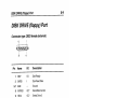
PARALLEL Port
8-4
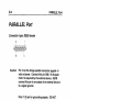
PARALLEL Port
Connector type: D825 female
13
25
Caution
14
Pin 14 on the Amiga parallel connector supplies +5
volts of power. Connect this pin ONLY if the power
from it is required by the external device. NEVER
connect this pin to an output of an external device or
to a signal ground.
Pins 17-25 are for grounding signals. DO NOT
connect these pins directly to a shield ground.
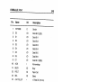
PARALLEL Port
8-5
Name
I/O
Description
1
(STROBE
0
Strobe
2
DO
I/O
Data Bit 0 (LSB)
3
01
I/O
Data Bit 1
4
02
I/O
Data Bit 2
5
03
I/O
Data Bit 3
6
04
I/O
Data Bit 4
7
05
I/O
Data Bit 5
8
D6
I/O
Data Bit 6
9
D7
I/O
Data Bit 7 (MSB)
Pin
10
(ACK
11
12
BUSY
I/O
Busy
POUT
I/O
Paper Out
SEL
1/0
13
14
Acknowledge
+5V PULLUP
Select
+5 Volts DC (10 mA)
15
16
(RESET
17
GND
Signal Ground
18
19
20
21
22
GND
Signal Ground
GND
Signal Ground
GND
Signal Ground
GND
Signal Ground
GND
Signal Ground
23
24
GND
Signal Ground
GND
Signal Ground
25
GND
Signal Ground
n/c
0
Reset
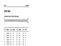
VIDEO Port
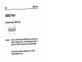
8-6
VIDEO Por t
Conn ector type: 0823 male
12
13
Caution
23
Pins 21, 22 and 23 on the RGe monito r conne ctor are
used for external power. Conne ct these pins ONLY if
power from them is required by the external device.
Pins 16-20 are used for signal ground . DO NOT
conne ct these to Pin 13.
8-7
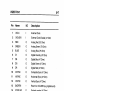
VIDEO Port
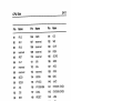
1/0
Description
Pin
Name
1
IXCLK
External Clock
2
IXCLKEN
External Clock Enable (47 Ohm)
3
RED
4
GREEN
10
ICSYNC
0
0
0
0
0
0
0
0
11
IHSYNC
0
Horizontal Sync (47 Ohm)
12
NSYNC
0
Vertical Sync (47 Ohm)
13
GNDRTN
14
IPIXELSW
0
Genlock overlay (47 Ohm)
15
IC1
0
Clock Out (47 Ohm)
16
GND
Video ground
17
GND
Video ground
18
19
20
21
22
23
GND
Video ground
GND
Video ground
5
BLUE
6
DI
7
DB
8
DG
9
DR
Analog Red (75 Ohm)
Analog Green (75 Ohm)
Analog Blue (75 Ohm)
Digital Intensity (47 Ohm)
Digital Blue (47 Ohm)
Digital Green (47 Ohm)
Digital Red (47 Ohm)
Composite Sync (47 Ohm)
Return for IXCLKEN (e.g. digital ground)
GND
Video ground
-12V
-12 Volts DC (10 mA)
+12V
+12 Volts DC (100 mA)
+5V
+5 Volts DC (100 mA)
8-8
MOUSE Ports
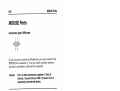
MOUSE Ports
Connector type: D89 male
1
5
rr1-11)
@~fOT:J@
6
9
To use a mouse to control the Workbench, you must attach it to the
MOUSE port (connector 1). You can attach joysticks, light pens,
and other controllers to either of the connectors.
Caution
Pin 7 on both connectors supplies +5 Volts DC
(50 mA). Connect this pin ONL V if power from it is
required by the external device.
Pin Mouse I
Trackball
Light Pen
Digital
Joystick
Proportional
Joystick
(Forward
Button 3*
(Back
n/c
(Left
Button 1
(Right
Button 2
I/O
1
V-pulse
2
H-pulse
3
VQ-pulse
4
HQ-pulse
n/c
n/c
n/c
n/c
5
Button 3 (M)*
Pen Press
n/c
PotX
1**
6
Button 1 (L)
(Beam
Trigger
(Button 1
n/c
1**
7
+5V
+5V
+5V
+5V
8
GND
GND
GND
GND
9
Button 2 (R)
Button 2*
Button 2*
PotY
'These buttons are optional.
"These pins may also be configured as outputs.
1**
DISK DRIVE (floppy) Port
8-9
DISK DRIVE (floppy) Port
Connector type: D823 female (external)
12
23
13
Name
1/0
Description
1
IRDY
I/O
Disk Ready
2
IDKRD
Pin
~-7
Disk Read Data
GND
Ground
8
IMTRXD
OC'
Disk Motor Control
9
ISEL2
OC'
Select Drive 2
10 IDRES
OC'
Disk Reset
11
ICHNG
I/O
Disk Removed From Drive--Latched Low
12
+5V
+5 Volts DC (250 mA maximum)
13 ISIDE
0
Select Disk Side--O=Upper, 1=Lower
14 IWPRO
I/O
Disk Is Write Protected
15
ITKO
I/O
Drive Head Position Over Track 0
16
IDKWE
OC'
Disk Write Enable
17
IDKWD
OC'
Disk Write Data
18 ISTEP
OC'
Step The Head--Pulse, First Low, Then High
19
DIR
OC'
Select Head Direction--O=lnner,
20
ISEL3
OC'
Select Drive 3
21
ISEL1
OC'
Select Drive 1
22
IINDEX
I/O
Disk Index Pulse
23
+12V
'OC=open collector
+12 Volts DC (160 mA max.)
1=Outer
8-10
CPU Slot
CPU Slot
Connector type: 1S0-pin male edge
2
1W
11111111111111111111111111111111111111111111111111111111111111111
149
Pin
Name
Pin
Name
Pin
Name
Pin
Name
1
reserved
A15
3
reserved
018
61
62
63
64
65
66
67
68
69
70
71
72
73
74
75
76
015
reserved
41
42
43
44
45
46
47
48
49
50
51
52
53
54
55
56
57
58
59
60
031
2
21
22
23
24
25
26
27
28
29
30
31
32
33
34
35
36
37
38
39
40
017
77
01
016
78
79
80
00
4
reserved
5
reserved
6
reserved
7
reserved
8
reserved
9
GNO
10
11
12
13
14
15
16
+5VOC
17
A17
18
19
20
A16
A23
A22
A21
A20
A19
A18
GNO
+5VOC
A14
A13
A12
A11
A10
A9
A8
GNO
+5VOC
A7
A6
A5
A4
A3
A2
A1
AO
GNO
+5VOC
030
029
028
027
026
025
024
GNO
+5VOC '
023
022
021
020
019
GNO
+5VOC
014
013
012
011
010
09
08
GNO
+5VOC
07
.06
05
04
03
02
GNO
+5VOC
CPU Slot
8-11
Pin
Name
Pin
Name
Pin
Name
81
IIPL2
106
IRMC
131
IOE
82
IIPL 1
107
reserved
132
IWE
83
IIPLD
108
reserved
133
IOVR
84
85
reserved
reserved
reserved
134
135
XRDY
IRST
109
110
IZORRO
86
IHLT
111
IBR
136
IWIDE
87
reserved
112
IBG
137
IINT2
88
reserved
113
reserved
138
IINT6
SIZE1
114
IBOSS
139
GND
90
SIZED
115
IFPUCS
140
+5VDC
91
IAS
116
IFPUSENSE
141
$YSTEM1 (GND)
92
IDS
117
CCKA
142
SYSTEMD (GND)
93
RIW
118
IRESET
143
IxRxD
94
IBERR
119
GND
144
IxTxD
95
reserved
120
+5VDC
145
ICONFIG OUT
96
IAVEC
121
INETCS
146
AUDIO GND
97
IDSACK1
122
ISPARECS
147
AUDIO LEFT
98
IDSACK2
123
IRTCCS
148
AUDIO RIGHT
99
CPUCLKA
124
IFLASH
149
+12VDC
100
E Clock
125
IREG
150
-12VDC
101
GND
126
ICCENA
102
+5VDC
127
IWAIT
103
FC2
128
IKBRESET
104
FC1
129
IIORD
105
FCD
130
IIOWR
89
AppendixC
Using Floppy Disks
Floppy disks are a type of portable magnetic recording media that is
used to:
•
transfer information from one computer to another.
install software on a system's hard drive.
make backup copies of your software and data.
When you insert a floppy disk into the system's floppy disk drive,
you can read the information stored on the disk and write
information to the disk.
Using 3.S-lnch Floppy Disks
Your computer system comes with a 3.5-inch disk drive installed.
This drive accepts standard double-density (880 KB storage
capacity) floppy disks.
Figure C-l illustrates a floppy disk. Double-density disks have a
write-protect tab in one corner.
To write-protect a disk, slide the plastic write-protect tab to uncover
the hole.
Using 3.5-lnch Floppy Disks
C-2
077~'5%:1575:'~>;;:----
Write protected position
Back of 3.5 inch disk
0
0
=
[
Write enabled position
0
Shutter
Figure C-1. 3.5-inch floppy disk
Figure C-2 illustrates inserting a disk into the disk drive. When
you push the disk all the way into the drive, the disk will click down
into place. To release the disk, push the disk eject button on the
lower right side of the disk opening.
Guidelines for Using Disks
C-3
Figure C-2. Inserting a floppy disk
Guidelines for Using Disks
•
Most important: Never remove a disk from a drive while the
drive is in use. Always wait a few seconds after the drive light
has gone out before removing it, rebooting, or turning the
computer off, as sometimes there is some additional disk activity
after a moment.
Disk errors may be caused by interrupting disk activity. These
can often be repaired using a disk recovery utility. See your
Amiga software documentation for more information.
•
Make copies (working disks) ofimport~nt disks. Work with the
copies and keep the originals in a safe place for use as backups if
the copies become damaged. See your Amiga software
documentation for information on copying disks.
Don't touch or scratch any exposed portion of the disk's shiny
surface, or allow dust or moisture to collect on the disk.
Store disks at a temperature range between 50 0 and 1200 F.
•
•
•
Keep disks away from devices with strong magnetic fields, such
as televisions, electric motors, speakers, etc.
Guidelines for Using Disks
C-4
•
You must format a new disk before you use it for storing data.
Before you begin the format, make sure the disk doesn't contain
anything you want to save. Formatting a disk will erase all
data stored on it.
Floppy disks may be formatted with the original Amiga file system
(OFS), the Fast File System (FFS), or the MS-DOS compatible
CrossDOS file system. You can also format disks (OFS and FFS
only) with a directory-caching option for faster response in opening
disk windows and reading disk directories. This option slightly
decreases the amount of space on the disk.
You therefore have the following options in formatting disks in the
Amiga's floppy drive.
Table C-1. Floppy formatting options
Amiga File System
Approximate Formatted Capacity
OFS
837 KB
FFS
879 KB
DC-OFS
837 KB
DC-FFS
879 KB
CrossDOS
720 KB
Note
Disks formatted with the directory-caching option
cannot be read by Amigas with earlier versions of
the system software. Do not format a disk with the
directory-caching option if you need to use the disk
to transfer files to an Amiga with Release 2 or
earlier system software.
Also, you should not attempt to use standard disk
repair utilities on such disks. Disk utilities not
developed with the directory-caching feature in
mind will not properly recognize the new disk
format and could damage the data on the disks.
AppendixD
Amiga Character Set
The Amiga uses the ECMA-94 Latin 1 InternationalS-bit character
set. The following tables list the printable characters in the lower
and upper portions of the character set, by character code.
Table D-1. Amiga Character Set (lower)
Code
32 sp
33
34 "
35 #
36 $
37 %
38 &
39 '
Code
Code
Code
48 0
64
49
65 A
66 B
Code
Code
80 P
81 Q
96
97 a
112 P
113 q
82 R
98 b
114 r
67 C
83 S
99 c
115 s
68 D
84 T
100 d
116
53 5
54 6
69 E
70 F
85 U
101 e
117 u
86 V
102 f
118 v
55 7
87 W
103 9
104 h
119 w
89 Y
90 Z
105
106
121 Y
122 z
91
107 k
123
50 2
51 3
52 4
@
40
56 8
71 G
72 H
41
42 *
57 9
73 I
58
43 +
44
59
74 J
75 K
60 <
61
124
77 M
92 \
93 1
108
45 -
109 m
125
46
62 >
78 N
94
110 n
126 -
47 /
63 ?
79 0
95
76 L
88 X
1\
111
0
120 x
Amiga Character Set
D-2
Table D-2. Amiga Character Set (upper)
Code
Code
160
161
162
163
164
165
166
167
168
sp
e
£
a
¥
§
..
169 ©
170 11
171 «
172 ..,
173 174 ®
175 -
176
177
178
179
180
181
182
183
184
185
186
187
188
189
190
191
Code
Code
0
±
2
3
I.l
'11
1
Q
»
1,4
Y2
%
i
192
193
194
195
196
197
198
199
200
201
202
203
204
205
206
207
A
A
A
A
A
A
,LE
Q
E
E
E
E
208
209
210
211
212
213
214
215
216
217
218
219
220
221
222
223
Code
f)
N
6
6
6
6
0
x
0
CJ
U
0
0
Y
P
B
224
225
226
227
228
229
230
231
232
233
234
235
236
237
238
239
Code
El
a
a
a
a
a
ffi
t;:
El
El
e
e
1
240
241
242
243
244
245
246
247
248
249
250
251
252
253
254
255
0
ii
Cl
6
6
6
0
0
U
u
0
0
Y
P
If
Index
68030,3-2
68EC020, ix, A-1
arrow keys, xi, 2-8, 2-9
assignments, 5-3
attaching external devices
floppy drive, 1-12
monitor, 1-6
mouse, 1-5
parallel device, 1-12
serial device, 1-12
audio connection, 1-10
audio equipment, 1-11
audio jacks, 1-10, A-1
A
B
AA chip set, ix, A-1
AC outlet, 1-13, 3-3
accelerator boards, 3-2
accessory, PCMCIA, 4-1, 5-2, 5-6
active low, B-1
adapter
23-pin to 15-pin, 1-7
75-ohm to 300-ohm, 1-7
graphics, 1-6
SCART,1-7
Alt keys, 2-5, 2-9
Amiga Hard Drive User's Guide, xi,
5-3,5-5
Amiga keys, xi, 2-9
analog RGB, A-1, A-2
analog RGB monitor, 1-6
application disk, 2-1
Backspace, 2-7
backup disks, C-1
battery, memory card, 4-3
bitplanes, A-2
boot priority, 5-4
boot volume, 5-3
bootable disks, 5-4
bootable floppy disk, 2-1
bootable partition, 5-4
booting, 1-14,2-1,5-4
1
15 KHz monitor, 1-6
6
c
Caps Lock, 2-6
card disk, 4-3, 5-2
Index-2
card slot, PCMCIA, 1-4, 4-1, 5-1
CD-ROM drive, 3-2, 5-6
Channel Select switch, 1-8
Chip memory, 3-1, A-1
cleaning mouse, 5-6
clock speed, A-1
clock/calendar, 3-1, A-2
COMP. (composite) jack, 1-6, A-1
composite input, 1-8
composite monitor, 1-7
connecting equipment, 1-2
connecting power, 1-13
connector pins, 5-6
connectors, 1-2, 8-1
conventions, x
CPU slot, x, 3-2, A-2, 8-10
credit card slot, A-1
CrossDOS, C-4
Ctrl,2-6
cursor, 2-7, 2-8
custom chips, ix, 3-1, A-1
o
de-interlaced modes, 1-6
Del,2-8
DFO:, 2-1
DF1 :/DF2:, 1-12
directory-caching option, C-4
disconnecting equipment, 1-2
DISK DRIVE port, 1-12, A-1 , 8-9
disk errors, 4-4, 5-3, C-3
disk utilities, C-4
documentation, xi, 5-2
drive activity lights, 1-3, 2-3, 5-2,
C-3
drive alignment, 5-6
drive controller, 5-5
E
eject button, 1-3, C-2
electrical requirements, 1-1, 1-13
Enter, 2-6
Esc, 2-7
ESD,3-4
expansion options, 3-1
external connectors, 1-5, 5-1, 8-1
EXTERNAL VIDEO jack, 1-7
F
F connector, 1-7
Fast memory, 3-1,4-3, A-1
FFS, C-4
file transfer, C-4
floppy disks, 5-2, C-1
floppy drive, 2-3, 5-6, A-2
floppy drive connector, external,
1-12
floppy-based systems, 2-1 , 5-4
formatting disks, C-4
FPU, ix, A-1
function keys, 2-8
G
gadget shortcuts, 2-6
Glossary, xi
H
hard disk, x, 2-1, 3-2, 5-2
hard disk systems, 5-4
hardware failure, 5-3
Index-3
hardware installation, 5-5
Help, 2-8
Home, 2-8
horizontal scan rate, 1-6, A-2
left Amiga, 2-6
light pen, 1-12, B-8
M
I
IC chips, 3-4
IDE, 3-2, A-2
IDE interface, x
insertion, PCMCIA card, 4-2
installing options, 3-3
interactions, expansion device, 3-3
interference, electrical, 1-1
international keyboard, 2-5, A-2
interrupting disk activity, 5-2
J
joystick, attaching, 1-12
jumper, ID/unit number, 5-5
K
key combinations, x, 2-4, 2-9
key repeat, 2-5
keyboard, x, 2-2, 2-3, 5-2, A-2
keyboard equivalents, 2-9
keyboard shortcuts, 2-6
keymap, 2-4, 2-5, 5-2, A-2
keys, redefinition, 2-4
L
language settings, 2-2, 5-2
main keyboard, 2-5
main unit, x, 1-3, 5-3
making backup copies, 2-2
memory, 3-1, A-1
memory card, 3-2, 4-1
menu shortcuts, 2-6
microprocessor, ix, 3-1, A-1
MIDI interface, attaching, 1-12
modem, 1-12,3-2,4-4,5-2
monitor, 2-3, 5-3
composite, 1-7
monaural,1-11
multiscan, 1-6
RGB,1-6
stereo, 1-11
monitor cable, 5-3
monitor compatibility, 1-6, A-2
motherboard, 1-2, A-1
mouse, 1-5, 2-9, 3-3, 5-1, 5-6
mouse buttons, 2-9
mouse packing material, 1-5
mouse pad, 1-5
MOUSE port, 1-5, A-1, B-8
MS-DOS, 2-8, C-4
multiscan monitor, 1-6
multitasking, 4-4
N
network access, 2-3
networking hardware, 3-2, 4-4
NTSC, 1-6, 1-7, A-2
numeric keypad, 2-7
Index-4
o
R
OFS, C-4
optional equipment, 1-6
RAM, 3-1, 4-2
RAM, CPU slot, 3-2
RCA jacks, 1-7, 1-10, A-1
rebooting, 2-3, 4-4, 5-2, C-3
remote access, 2-3
removable media drive, 5-6
requesters, 5-3
Return, xi, 2-6
RF MODULATOR jack, 1-6, 1-8,
1-9,A-1
RGB monitor, 1-6
ribbon cable, 5-5
right Amiga, 2-6
ROM, A-1
ROM card, 4-4
ROM version, 5-5
p
PAL, 1-6, 1-9, A-2
PAL Audio switch, 1-9
palette, ix, A-2
PARALLEL port, 1-12, A-1, B-4
PC emulators, 3-2
PCMCIA, x, 4-1
PCMCIA card, 3-2
PCMCIA slot, 3-2, A-1
peripherals, 1-2, 1-13, 2-3, 3-3,
5-6, B-1
PgDn,2-8
pinouts, B-1
pointer, 2-9
power connection, 1-6,5-5
power light, 1-3
power strip, 1-1,5-3
power supply, 1-13,5-5, A-2
power switch, 1-14,2-3
Preferences, 5-2
editors, 2-2
keymap,2-4
Screen Mode, A-2
preventing damage, 5-1
printer, 5-2
printer, attaching, 1-12
problems, 5-1
Q
qualifier keys, 2-5, 2-9
s
saving work, 2-3
scanner, 1-12
SCART, 1-6, 1-7, 1-9, HO
Screen Mode, 5-4
SCSI adapter, 3-2, 4-4
SERIAL port, A-1, B-2
serial printer, attaching, 1-12
Shell, 4-3
Shift keys, 2-5, 2-7, 2-9
software
installation, 2-2, 3-3, 5-3
problems, 5-2
speakers, monitor, 1-11
special keys, 2-5, 2-6
startup problems, 5-3
Startup-sequence, 5-3
static electricity, 3-4
stereo sound output, x
surge protector, 1-1
switch box, 1-7
Index-5
switch, power, 1-14
switch, write protection, 4-2
symbol keys, 2-7
T
Tab, 2-7
tape drive, 3-2
termination, SCSI, 5-5
testing expansion devices, 3-3
text gadgets, 2-7
top panel, 1-3
troubleshooting, 5-1
turning off the Amiga, 2-3
u
unit number jumper, 5-5
v
VCR, 1-7
vertical scan rates, A-2
VGA-style connector, 1-7
VGAlSVGA monitor, 1-6
VIDEO IN jack, 1-7
video mode, default, 5-3
VIDEO port, 1-6, 1-10, A-1
Video Tuning screw, 1-9
voltage, 1-1,5-3
w
waiting before turning on, 2-3
warranties, 5-6
Workbench, 4-3, 4-4, 8-8
Workbench disk, 2-1 , 5-4
Workbench screen, 2-2, 4-3
Workbench User's Guide, xi, 2-2,
2-6, 4-2, 5-3, 5-5
write-protect tab, C-1
write-protection, card, 4-4
v
y adapter, 1-11