1
SITRANS F
Coriolis Flowmeters
SITRANS FC430 with HART
Operating Instructions
Edition
06/2012
Answers for industry.
Introduction
1
Safety notes
2
Description
3
SITRANS F
Installing/mounting
4
Coriolis Flowmeters
SITRANS FC430 with HART
Connecting
5
Commissioning
6
Operating
7
Functions
8
Custody Transfer
9
Operating Instructions
These Operating Instructions apply to Siemens
products SITRANS FC430 with order codes
commencing 7ME4613, 7ME4603, 7ME4623,
7ME4610, 7ME4620, 7ME4710, and 7ME4713
06/2012
A5E03361511-03
Alarms and system
messages
10
Service and maintenance
11
Troubleshooting/FAQs
12
Technical data
13
Spare parts/Accessories
14
Dimensions and weight
15
LUI menu structure
A
HART commands
B
Zero point adjustment
C
Legal information
Warning notice system
This manual contains notices you have to observe in order to ensure your personal safety, as well as to prevent
damage to property. The notices referring to your personal safety are highlighted in the manual by a safety alert
symbol, notices referring only to property damage have no safety alert symbol. These notices shown below are
graded according to the degree of danger.
DANGER
indicates that death or severe personal injury will result if proper precautions are not taken.
WARNING
indicates that death or severe personal injury may result if proper precautions are not taken.
CAUTION
indicates that minor personal injury can result if proper precautions are not taken.
NOTICE
indicates that property damage can result if proper precautions are not taken.
If more than one degree of danger is present, the warning notice representing the highest degree of danger will be
used. A notice warning of injury to persons with a safety alert symbol may also include a warning relating to property
damage.
Qualified Personnel
The product/system described in this documentation may be operated only by personnel qualified for the specific
task in accordance with the relevant documentation, in particular its warning notices and safety instructions. Qualified
personnel are those who, based on their training and experience, are capable of identifying risks and avoiding
potential hazards when working with these products/systems.
Proper use of Siemens products
Note the following:
WARNING
Siemens products may only be used for the applications described in the catalog and in the relevant technical
documentation. If products and components from other manufacturers are used, these must be recommended or
approved by Siemens. Proper transport, storage, installation, assembly, commissioning, operation and
maintenance are required to ensure that the products operate safely and without any problems. The permissible
ambient conditions must be complied with. The information in the relevant documentation must be observed.
Trademarks
All names identified by ® are registered trademarks of Siemens AG. The remaining trademarks in this publication
may be trademarks whose use by third parties for their own purposes could violate the rights of the owner.
Disclaimer of Liability
We have reviewed the contents of this publication to ensure consistency with the hardware and software described.
Since variance cannot be precluded entirely, we cannot guarantee full consistency. However, the information in
this publication is reviewed regularly and any necessary corrections are included in subsequent editions.
Siemens AG
Industry Sector
Postfach 48 48
90026 NÜRNBERG
GERMANY
Order number: A5E03361511
Ⓟ 02/2013 Technical data subject to change
Copyright © Siemens AG 2012.
All rights reserved
Table of contents
1
2
3
4
5
Introduction...................................................................................................................................................9
1.1
History...........................................................................................................................................9
1.2
Items supplied...............................................................................................................................9
1.3
Checking the consignment..........................................................................................................11
1.4
Device identification.....................................................................................................................11
Safety notes................................................................................................................................................19
2.1
Laws and directives.....................................................................................................................19
2.2
Installation in hazardous locations...............................................................................................20
2.3
Certificates...................................................................................................................................23
Description..................................................................................................................................................25
3.1
System configuration...................................................................................................................26
3.2
Design.........................................................................................................................................27
3.3
Features......................................................................................................................................32
3.4
HART Communication Interface..................................................................................................34
3.5
Theory of operation.....................................................................................................................37
Installing/mounting......................................................................................................................................39
4.1
Introduction..................................................................................................................................39
4.2
Strong vibrations..........................................................................................................................39
4.3
4.3.1
4.3.2
4.3.3
4.3.4
4.3.5
Sensor installation.......................................................................................................................39
Installation safety precautions.....................................................................................................39
Determining a location ................................................................................................................41
Orientation of the sensor.............................................................................................................42
Mounting the sensor....................................................................................................................44
Mounting a pressure guard..........................................................................................................46
4.4
4.4.1
4.4.2
4.4.3
4.4.4
4.4.5
4.4.6
Transmitter installation................................................................................................................48
Introduction..................................................................................................................................48
Wall mounting..............................................................................................................................49
Pipe mounting..............................................................................................................................49
Mounting the transmitter..............................................................................................................50
Turning the transmitter................................................................................................................50
Turning the local display..............................................................................................................52
Connecting..................................................................................................................................................53
5.1
General safety requirements.......................................................................................................53
5.2
Wiring in hazardous locations......................................................................................................54
5.3
Cable requirements.....................................................................................................................54
SITRANS FC430 with HART
Operating Instructions, 06/2012, A5E03361511-03
3
Table of contents
6
7
5.4
Safety notes for connecting.........................................................................................................55
5.5
Step 1: Connecting the sensor and the transmitter.....................................................................56
5.6
Lack of equipotential bonding......................................................................................................59
5.7
Step 2: Preparing for the transmitter connections.......................................................................59
5.8
Step 3: Connecting the power supply..........................................................................................63
5.9
Missing PE/ground connection....................................................................................................65
5.10
Step 4a: Connecting the current output HART (channel 1).........................................................65
5.11
Step 4b: Connecting the inputs and outputs (channels 2 to 4)....................................................66
5.12
Step 5: Finishing the transmitter connection...............................................................................69
Commissioning...........................................................................................................................................71
6.1
General requirements..................................................................................................................71
6.2
Warnings.....................................................................................................................................71
6.3
6.3.1
6.3.2
6.3.3
6.3.4
Commissioning via LUI................................................................................................................72
Introduction..................................................................................................................................72
Overview......................................................................................................................................72
Quick Start...................................................................................................................................73
Zero point adjustment..................................................................................................................74
6.4
6.4.1
6.4.2
6.4.3
6.4.4
6.4.5
6.4.6
6.4.7
6.4.8
6.4.9
6.4.10
6.4.11
Commissioning with PDM............................................................................................................75
Operating via SIMATIC PDM.......................................................................................................76
Functions in SIMATIC PDM.........................................................................................................76
Features of SIMATIC PDM Rev. 6.1, SP4...................................................................................76
Initial setup..................................................................................................................................76
Configuring a new device............................................................................................................78
Wizard - Quick Start via PDM......................................................................................................78
Wizard - Zero Point adjustment...................................................................................................86
Changing parameter settings using SIMATIC PDM....................................................................87
Parameters accessed via drop-down menus..............................................................................88
Zero point adjustment..................................................................................................................89
Process variables........................................................................................................................91
Operating....................................................................................................................................................93
7.1
7.1.1
7.1.2
7.1.3
7.1.4
7.1.5
8
4
Local User Interface (LUI)...........................................................................................................93
Display view structure..................................................................................................................94
Access control.............................................................................................................................98
Operation view.............................................................................................................................98
Navigation view.........................................................................................................................104
Parameter view..........................................................................................................................110
Functions..................................................................................................................................................113
8.1
Process values..........................................................................................................................113
8.2
Zero point adjustment................................................................................................................114
8.3
Low flow cut-off..........................................................................................................................116
8.4
Empty tube monitoring...............................................................................................................116
SITRANS FC430 with HART
Operating Instructions, 06/2012, A5E03361511-03
Table of contents
9
10
11
8.5
Process noise damping.............................................................................................................117
8.6
8.6.1
8.6.2
8.6.3
8.6.4
8.6.4.1
8.6.5
8.6.6
8.6.6.1
Inputs and outputs.....................................................................................................................119
Current output............................................................................................................................120
Pulse output...............................................................................................................................125
Frequency output.......................................................................................................................127
Status output.............................................................................................................................128
Alarm status...............................................................................................................................128
Control output............................................................................................................................129
Input...........................................................................................................................................129
Input options..............................................................................................................................129
8.7
Totalizers...................................................................................................................................129
8.8
8.8.1
8.8.2
8.8.3
Dosing.......................................................................................................................................130
Valve control configuration........................................................................................................131
Dosing operation.......................................................................................................................137
Fault handling............................................................................................................................137
8.9
SensorFlash..............................................................................................................................138
8.10
Simulation..................................................................................................................................138
8.11
Maintenance..............................................................................................................................139
Custody Transfer......................................................................................................................................141
9.1
Introduction................................................................................................................................141
9.2
Operating conditions..................................................................................................................141
9.3
Verification.................................................................................................................................141
9.4
Setting up custody transfer mode..............................................................................................143
9.5
Parameter protection in custody transfer mode.........................................................................146
9.6
Disabling custody transfer mode...............................................................................................148
Alarms and system messages..................................................................................................................151
10.1
Overview of messages and symbols ........................................................................................151
10.2
Alarm messages........................................................................................................................153
Service and maintenance.........................................................................................................................161
11.1
Maintenance..............................................................................................................................161
11.2
Service information....................................................................................................................161
11.3
Recalibration..............................................................................................................................161
11.4
Technical support......................................................................................................................162
11.5
Transportation and storage.......................................................................................................163
11.6
Cleaning....................................................................................................................................163
11.7
Maintenance work.....................................................................................................................164
11.8
11.8.1
Repair........................................................................................................................................165
Unit repair..................................................................................................................................165
11.9
Return and disposal...................................................................................................................166
SITRANS FC430 with HART
Operating Instructions, 06/2012, A5E03361511-03
5
Table of contents
11.9.1
11.9.2
12
13
14
15
6
Return procedures.....................................................................................................................166
Device disposal.........................................................................................................................167
Troubleshooting/FAQs..............................................................................................................................169
12.1
Diagnosing with PDM................................................................................................................169
12.2
12.2.1
12.2.2
12.2.3
12.2.4
Troubleshooting sensor-related problems.................................................................................169
Step 1: Inspecting the application..............................................................................................170
Step 2: Performing a zero point adjustment..............................................................................170
Step 3: Calculating the measurement error...............................................................................170
Step 4: Improving the application..............................................................................................172
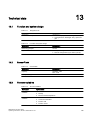
Technical data..........................................................................................................................................175
13.1
Function and system design......................................................................................................175
13.2
SensorFlash..............................................................................................................................175
13.3
Process variables......................................................................................................................175
13.4
Bus communication...................................................................................................................176
13.5
Performance..............................................................................................................................176
13.6
Rated operating conditions........................................................................................................178
13.7
Pressure drop curves................................................................................................................179
13.8
Pressure - temperature ratings..................................................................................................179
13.9
Design.......................................................................................................................................180
13.10
Inputs and outputs.....................................................................................................................181
13.11
Local User Interface..................................................................................................................183
13.12
Power supply.............................................................................................................................183
13.13
Cables and cable entries...........................................................................................................183
13.14
Installation torques....................................................................................................................185
13.15
Certificates and approvals HART..............................................................................................186
13.16
13.16.1
13.16.2
13.16.3
13.16.4
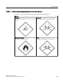
PED...........................................................................................................................................188
Division according to the danger potential.................................................................................188
Division of media (liquid/gaseous) into the fluid groups............................................................189
Conformity assesment...............................................................................................................190
Diagrams...................................................................................................................................191
Spare parts/Accessories...........................................................................................................................193
14.1
Ordering.....................................................................................................................................193
14.2
Replaceable components..........................................................................................................193
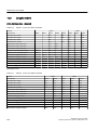
Dimensions and weight.............................................................................................................................197
15.1
Sensor dimensions....................................................................................................................197
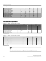
15.2
Lengths matrix...........................................................................................................................198
15.3
Transmitter dimensions.............................................................................................................201
15.4
Mounting bracket.......................................................................................................................202
SITRANS FC430 with HART
Operating Instructions, 06/2012, A5E03361511-03
Table of contents
A
B
LUI menu structure...................................................................................................................................203
A.1
Menu structure overview...........................................................................................................203
A.2
Main menu.................................................................................................................................203
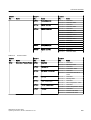
A.3
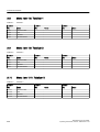
Menu item 1.3: Massflow...........................................................................................................204
A.4
Menu item 1.4: Volumeflow.......................................................................................................205
A.5
Menu item 1.5: Density..............................................................................................................205
A.6
Menu item 1.6 Fluid temperature...............................................................................................205
A.7
Menu item 1.7: Fraction.............................................................................................................205
A.8
Menu item 1.8: Totalizer 1.........................................................................................................206
A.9
Menu item 1.9: Totalizer 2.........................................................................................................206
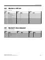
A.10
Menu item 1.10: Totalizer 3.......................................................................................................206
A.11
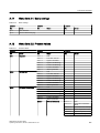
Menu item 2.1: Basic settings....................................................................................................207
A.12
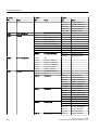
Menu item 2.2: Process values.................................................................................................207
A.13
Menu item 2.3: Totalizer............................................................................................................209
A.14
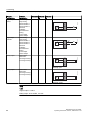
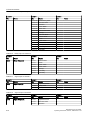
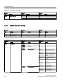
Menu item 2.4: Inputs/Outputs..................................................................................................210
A.15
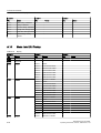
Menu item 2.5: Dosing...............................................................................................................214
A.16
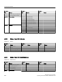
Menu item 2.6: Zero point adjustment.......................................................................................217
A.17
Menu item 2.7: Safe operation..................................................................................................217
A.18
Menu item 2.8: Display..............................................................................................................218
A.19
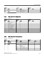
Menu item 3.1: Identification......................................................................................................219
A.20
Menu item 3.2: Alarms...............................................................................................................220
A.21
Menu item 3.3: Maintenance.....................................................................................................220
A.22
Menu item 3.4: Diagnostics.......................................................................................................221
A.23
Menu item 3.5: Characteristics..................................................................................................221
A.24
Menu item 3.6: SensorFlash......................................................................................................222
A.25
Menu item 3.7: Simulate............................................................................................................222
A.26
Menu item 3.8: Self test.............................................................................................................224
A.27
Menu item 3.9: Dosing test........................................................................................................224
A.28
Menu item 4.6: Mapping of variables.........................................................................................224
A.29
Menu item 4.7: HART units.......................................................................................................225
A.30
Menu item 5.1: Access management........................................................................................225
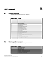
HART commands.....................................................................................................................................227
B.1
Universal commands.................................................................................................................227
B.2
Common practice commands....................................................................................................227
SITRANS FC430 with HART
Operating Instructions, 06/2012, A5E03361511-03
7
Table of contents
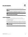
C
Zero point adjustment...............................................................................................................................229
Glossary....................................................................................................................................................233
Index.........................................................................................................................................................235
8
SITRANS FC430 with HART
Operating Instructions, 06/2012, A5E03361511-03
1
Introduction
These instructions contain all information required to commission and use the device. It is your
responsibility to read the instructions carefully prior to installation and commissioning. In order
to use the device correctly, first review its principle of operation.
The instructions are aimed at persons mechanically installing the device, connecting it
electronically, configuring the parameters and commissioning it, as well as service and
maintenance engineers.
The contents of this manual shall not become part of or modify any prior or existing agreement,
commitment or legal relationship. The sales contract contains all obligations on the part of
Siemens as well as the complete and solely applicable warranty conditions. Any statements
regarding device versions described in the manual do not create new warranties or modify the
existing warranty.
The content reflects the technical status at the time of publishing. Siemens reserves the right
to make technical changes in the course of further development.
1.1
History
The following table shows major changes in the documentation compared to the previous
edition.
Edition
Remarks
SW version
03/2012
First edition
● SIMATIC PDM driver 1.00.00
06/2012
Second edition
● SIMATIC PDM driver 1.00.00
CT chapter included
FW revision
● Standard version:
–
Compact: 03.00.00-10
–
Remote: 02.00.00-30
● CT version:
1.2
–
Compact: 03.00.00-11
–
Remote: 02.00.00-31
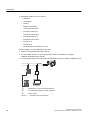
Items supplied
The device can be delivered as either a compact or a remote system.
SITRANS FC430 with HART
Operating Instructions, 06/2012, A5E03361511-03
9
Introduction
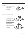
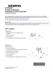
1.2 Items supplied
Compact system
/
● SITRANS FC430 sensor and compact
mounted transmitter
● Packet of cable glands
● Quick Start guide
● CD containing software, certificates and
device manuals
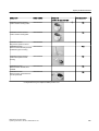
Remote system
● SITRANS FCS400 sensor
● SITRANS FCT030 transmitter with
M12 socket assembled
● Mounting bracket and cushion pad
● Sensor cable with M12 connector
/
Remote with M12 plug connection
● Packet of cable glands
● Quick Start guide
● CD containing software, certificates
and device manuals
● SITRANS FCS400 sensor
● SITRANS FCT030 transmitter with
terminal housing assembled
● Mounting bracket and cushion pad
● Sensor cable
/
Remote with sensor terminal housing
● Packet of cable glands
● Quick Start guide
● CD containing software, certificates
and device manuals
10
SITRANS FC430 with HART
Operating Instructions, 06/2012, A5E03361511-03
Introduction
1.4 Device identification
Note
Scope of delivery may vary, depending on version and add-ons. Make sure the scope of
delivery, and the information on the nameplate corresponds to your order and the delivery
note.
Inspection
1. Check for visual mechanical damage due to possible improper handling during shipment.
All claims for damage are to be made promptly to the carrier.
2. Make sure the scope of delivery, and the information on the type plate corresponds to your
order and the delivery note.
1.3
Checking the consignment
1. Check the packaging and the device for visible damage caused by inappropriate handling
during shipping.
2. Report any claims for damages immediately to the shipping company.
3. Retain damaged parts for clarification.
4. Check the scope of delivery by comparing the shipping documents with your order for
correctness and completeness.
WARNING
Using a damaged or incomplete device
Danger of explosion in hazardous areas.
● Do not use any damaged or incomplete devices.
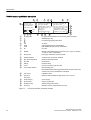
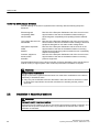
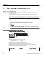
1.4
Device identification
Each part of the FC430 Coriolis flowmeter has three nameplate types showing the following
information:
● product identification
● product specifications
● certificates and approvals
Note
Identification
Identify your device by comparing your ordering data with the information on the product
and specification nameplates.
SITRANS FC430 with HART
Operating Instructions, 06/2012, A5E03361511-03
11
Introduction
1.4 Device identification
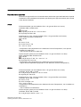
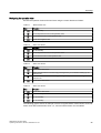
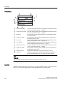
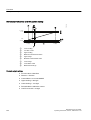
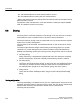
FCS400 sensor identification nameplate
&RULROLV)ORZ6HQVRU6,75$16)&6
6\VWHPRUGHUQR 0(/$*&=$%()
6HULDOQR)'.%
&///0<<<
6HQVRURUGHUQR 0(/$*&=$%()
6HQ
///0<<
6LHPHQV$6)ORZ,QVWUXPHQWV1RUGERUJ'HQPDUN
0DGHLQ'HQPDUN
/
①
②
③
④
⑤
⑥
Product name
Sensor product name
Serial no.
Flowmeter serial number
Manufacturer
Manufacturer name and location
Country
Manufacturing country
Sensor order no.
Sensor replacement order number
System order no.
Device-specific system order number (transmitter and sensor)
Figure 1-1
FCS400 identification nameplate example
The flowmeter serail number is constructed as follows:
PPPYMDDxxxxxx
where
PPP = Production factory (Siemens Flow Instruments: FDK)
Y = Production year (for encryption, see below)
M = Production month (for encryption, see below)
DD = Production date (for encryption, see below)
xxxxxx = Sequential number
Encryption:
Calendar year (Y)
1950, 1970, 1990, 2010
1951, 1971, 1991, 2011
1952, 1972, 1992, 2012
1953, 1973, 1993, 2013
1954, 1974, 1994, 2014
1955, 1975, 1995, 2015
1956, 1976, 1996, 2016
1957, 1977, 1997, 2017
1958, 1978, 1998, 2018
1959, 1979, 1999, 2019
1960, 1980, 2000, 2020
1961, 1981, 2001, 2021
1962, 1982, 2002, 2022
1963, 1983 2003, 2023
12
Code
A
B
C
D
E
F
H (G)
J
K
L
M
N
P
R
SITRANS FC430 with HART
Operating Instructions, 06/2012, A5E03361511-03
Introduction
1.4 Device identification
1964, 1984, 2004, 2024
1965, 1985, 2005, 2025
1966, 1986, 2006, 2026
1967, 1987, 2007, 2027
1968, 1988, 2008, 2028
1969, 1989, 2009, 2029
Month (M)
January
February
March
April
May
June
July
August
September
October
November
December
Date (DD)
Day 1 to 31
SITRANS FC430 with HART
Operating Instructions, 06/2012, A5E03361511-03
S
T
U
V
W
X
Code
1
2
3
4
5
6
7
8
9
O
N
D
Code
01 to 31 (corresponding to the actual date)
13
Introduction
1.4 Device identification
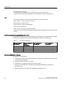
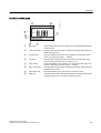
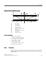
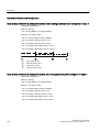
FCS400 sensor specification nameplate
,,*
,,'
①
②
③
④
⑤
Ex approvals
<HDURIPDQXIDFWXUH
&DOIDFWRU
TP PLQ NJK
TP QRP NJK
,69L 9OL $3L :
(QFORVXUH,37\SH;
$PELHQWWHPSWRr&
$FFXUDF\ssNJP
Ex approval specifications for the sensor (ATEX example)
WEEE (Page 167)
Consult the operating instructions
CE
CE mark
⑥
⑦
0539
0200
ATEX Notified Body ID (UL-DEMKO)
PED Notified Body ID (Force Certification)
Ex
Ex mark
MAWP
⑧
⑨
⑩
⑪
⑫
⑬
⑭
Maximum allowable working pressures at 20 °C (68 °F) and 200
°C (392 °F) (max. temperature)
Fluid group
Fluid group statement required by PED
Wetted material
Tube/process connection materials
Min. fluid temperature
Minimum fluid temperature
⑮
⑯
⑰
⑱
⑲
⑳
Size DN
Nominal size
Rating
Pressure rating
Conn.
Process connection type and size
Year of Manufacture
Manufacturing year
More detailed manufacturing date information is given in the serial
number found on the identification nameplate
Cal. Factor
Calibration factor
Qm (min)
Minimum and nominal flows with water at 20 °C (68 °F)
Qm (nom)
Power Supply
Power supply
Enclosure IP
Degree of protection
Ambient Temp.
Ambient temperature range
Accuracy
Massflow, density measurement accuracy
Figure 1-2
14
0$:3 36 DWr&EDU
0$:3 36 DWr& 76 EDU
)OXLGJURXS3('*
:HWWHGPDWHULDO
0LQIOXLGWHPSHUDWXUHr&
6L]H'1
5DWLQJ31
&RQQ(%'1
([GLD,,&7 *E
([WD,,,&7r&'D
6LUD$7(;;
,(&([6,5;
/
FCS400 specification nameplate example
SITRANS FC430 with HART
Operating Instructions, 06/2012, A5E03361511-03
Introduction
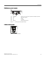
1.4 Device identification
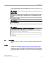
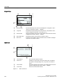
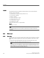
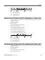
FCS400 sensor approval nameplate
)&
①
②
③
④
⑤
WARNING
Warning: Do not open when an explosive atmosphere is present
CSA
FM/CSA/UL approval
3A
3A logo
C✓
C-tick logo
Barcode
Product-specific barcode
Figure 1-3
FCS400 approval nameplate example
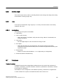
)&
FCS400 EHEDG nameplate
Figure 1-4
EHEDG nameplate
SITRANS FC430 with HART
Operating Instructions, 06/2012, A5E03361511-03
15
Introduction
1.4 Device identification
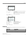
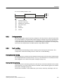
FCT030 transmitter identification nameplate
&RULROLV7UDQVPLWWHU6,75$16)&7
①
②
③
④
⑤
⑥
⑦
⑧
⑨
⑩
⑪
⑫
⑬
Product name
Transmitter product name
System order no.
Device-specific system order number (transmitter and sensor)
Transm. order no.
Transmitter replacement order number
Power Supply
Power supply
Material
Transmitter housing material and style (compact/remote)
Conduit / cable entries
Type of conduit / cable entries
Manufacturer
Manufacturer name and location
Country
Manufacturing country
Serial no.
Flowmeter serial number
System revisions
System revision numbers; firmware (FW) and hardware (HW)
Year of Manufacture
Manufacturing year
More detailed manufacturing date information is given in the serial
number (see sensor identification nameplate above)
Enclosure IP
Degree of protection
Ambient temp.
Ambient temperature
Figure 1-5
16
<HDURIPDQXIDFWXUH
(QFORVXUH,37\SH;
$PELHQWWHPSWRr&
6LHPHQV$6)ORZ,QVWUXPHQWV1RUGERUJ'HQPDUN
0DGHLQ'HQPDUN
6HULDOQR)'.%
6\VWHPUHYLVLRQV
):+:
6\VWHPRUGHUQR 0(/$*&=$%()
&///0<<<
7UDQVPRUGHUQR 0(/$*&=$%()
///0<<
3RZHU6XSSO\9DFWR+]9'&9$
0DWHULDO$OXPLQLXP5HPRWH
&RQGXLW&DEOHHQWULHV137ರ
/
FCT030 identification nameplate example
SITRANS FC430 with HART
Operating Instructions, 06/2012, A5E03361511-03
Introduction
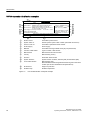
1.4 Device identification
FCT030 transmitter specification nameplate
/
,, *'
6:)XQFWLRQ6WDQGDUG
&KP$DFW+$57
&K6LJQDORXWSXWDFW
&K6LJQDORXWSXWSDV
&K6LJQDORXWSXWSDV
①
②
③
④
⑤
⑥
⑦
⑧
⑨
([GHLD>LD*D@,,&7*E
([WD>LD'D@,,,&7r&'E
6LUD$7(;;
,(&([6,5;
CE
CE mark
0539
ATEX Notified Body ID (UL-DEMKO)
Ex
Ex mark
SW Function
Software function ("Standard" or "CT standard")
Ch1
Communication interface on channel 1 (active or passive)
Ch2
Ch3
Ch4
Input/output setup of channels 2 to 4, if ordered
WEEE (Page 167)
Consult the operating instructions
Ex approvals
Figure 1-6
Ex approval specifications for the transmitter
FCT030 specification nameplate example
FCT030 transmitter approval nameplate
)&
&
86
①
②
③
④
⑤
WARNING
Warning: Do not open when an explosive atmosphere is present
FORCE OIML
Custody Transfer evaluation certificate number
C✓
C-tick logo
Barcode
Product-specific barcode
CSA
FM/CSA/UL approval
Figure 1-7
FCT030 approval nameplate example
SITRANS FC430 with HART
Operating Instructions, 06/2012, A5E03361511-03
17
Introduction
1.4 Device identification
Note
Custody transfer approval
Ensure that the "FORCE OIML cert. No." on the FCT030 transmitter approval nameplate is
identical to the number on the evaluation certificate supplied with the flowmeter.
Ensure that the CT-approved flowmeter serial number is stated on both the sensor
identification nameplate and on the transmitter identification nameplate ("Serial No.").
18
SITRANS FC430 with HART
Operating Instructions, 06/2012, A5E03361511-03
2
Safety notes
This device left the factory in good working condition. In order to maintain this status and to
ensure safe operation of the device, observe these instructions and all the specifications
relevant to safety.
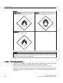
Observe the information and symbols on the device. Do not remove any information or symbols
from the device. Always keep the information and symbols in a completely legible state.
Symbol
Explanation
Consult operating instructions
Note
Functional safety applications (SIL)
In case the device is used in a functional safety application, refer to the functional safety
manual.
2.1
Laws and directives
Observe the test certification, provisions and laws applicable in your country during connection,
assembly and operation. These include, for example:
● National Electrical Code (NEC - NFPA 70) (USA)
● Canadian Electrical Code (CEC) (Canada)
Further provisions for hazardous area applications are for example:
● IEC 60079-14 (international)
● EN 60079-14 (EC)
SITRANS FC430 with HART
Operating Instructions, 06/2012, A5E03361511-03
19
Safety notes
2.2 Installation in hazardous locations
Conformity with European directives
The CE marking on the device symbolizes the conformity with the following European
directives:
Electromagnetic
compatibility EMC
2004/108/EC
Low voltage directive LVD
2006/95/EC
Atmosphère explosible
ATEX
94/9/EC
Pressure equipment
directive PED
97/23/EC
Directive of the European Parliament and of the Council on the
approximation of the laws of the Member States relating to
electromagnetic compatibility and repealing Directive 89/336/
EEC.
Directive of the European Parliament and of the Council on the
harmonisation of the laws of Member States relating to electrical
equipment designed for use within certain voltage limits.
Directive of the European Parliament and the Council on the
approximation of the laws of the Member States concerning
equipment and protective systems intended for use in potentially
explosive atmospheres.
Directive of the European Parliament and of the Council on the
approximation of the laws of the Member States concerning
pressure equipment.
The applicable directives can be found in the EC conformity declaration of the specific device.
Further country or region-specific code conformity information is available on request.
WARNING
Improper device modifications
Danger to personnel, system and environment can result from modifications to the device,
particularly in hazardous areas.
● Only carry out modifications that are described in the instructions for the device. Failure
to observe this requirement cancels the manufacturer's warranty and the product
approvals.
2.2
Installation in hazardous locations
WARNING
Equipment used in hazardous locations
Equipment used in hazardous locations must be Ex-approved and marked accordingly. It is
required that the special conditions for safe use provided in the manual and in the Ex
certificate are followed!
20
SITRANS FC430 with HART
Operating Instructions, 06/2012, A5E03361511-03
Safety notes
2.2 Installation in hazardous locations
Hazardous area approvals
The device is approved for use in hazardous area and has the approvals listed below. Special
conditions for safe installation and operation specified by each approval authority are included
in the relevant certificate.
ATEX:
FCT030 transmitter (can be installed in Zone 1 for gas and Zone 21 for dust):
Certificate SIRA 11ATEX1342X
II 2(1) GD
Ex d e [ia Ga] IIC T6 Gb Ta = -40°C to +60°C
Ex Tb [ia Da] IIIC T85°C Db
FCS400 sensor + DSL (can be installed in Zone 1 for gas and Zone 20 for dust):
ATEX Certificate: SIRA 11ATEX1341X
II 1/2 GD
II 1D
Ex d ia IIC T* Gb
Ex Ta IIIC T135°C** Da
Ta = -40°C to +60°C
* Temperature class (dependent on the "Maximum Process Temperature", see "Special
Conditions for Safe Use")
** See "Special Condition for Safe Use"
FC430 compact system (can be installed in Zone 1 for gas and Zone 21 for dust):
ATEX certificate SIRA 12ATEX1102X
II 1/2 GD
Ex d e ia [ia GA] IIC T* Gb Ta = -40°C to ** °C
Ex Tb [ia Da] IIIC T 85°C Db
* Temperature class (dependent on the "Maximum Process Temperature")
** Upper ambient temperature (dependent on the "Maximum Process Temperature")
IECEx:
FCT030 transmitter (can be installed in Zone 1 for gas and Zone 21 for dust):
Certificate: IECEx SIR 11.0150X
Ex d e ia [ia Ga] IIC T6 Gb Ta = -40°C to +60°C.
Ex tb [ia Da] IIIC T85°C Db
FCS400 sensor + DSL (can be installed in Zone 1 for gas and Zone 20 for dust):
Certificate: IECEx SIR 11.0149X
Ex d ia IIC T* Gb
Ex ta IIIC T135dgC** Da
(Ta = -40°C to +60°C)
* Temperature class (dependent on the "Maximum Process Temperature", see "Conditions of
Certification")
** See "Conditions of Certification"
FC430 compact system (can be installed in Zone 1 for gas and Zone 21 for dust):
Certificate: IECEx SIR 12.0040X
Ex d e ia [ia Da] IIC Gb Ta= -40 to ** °C
SITRANS FC430 with HART
Operating Instructions, 06/2012, A5E03361511-03
21
Safety notes
2.2 Installation in hazardous locations
Ex tb [ia Da] IIIC T 85°C Db
* Temperature class (dependent on the "Maximum Process Temperature")
** Upper ambient temperature (dependent on the "Maximum Process Temperature")
FM:
Transmitter (FCT030), Sensor with DSL (FCS400) and Compact (FC430):
Class I Division 1 Groups A,B,C,D T* (XP, IS)
Class II Divison 1 Groups E,F,G
Class III Division 1 Group H (granulates)
Class I Zone 1 and Zone 21
Class 1 Zone 1 and Zone 20 (FCS400 remote)
*: Depends on media temperature, ambient temperature and configuration (compact or remote)
(T6-T2)
Maximum temperature specifications for Ex use
FCS400 sensor with DSL and FC430 temperature classification with and without dust is related
to the process temperature and ambient temperature as listed in the table below:
Table 2-1
Temperature classification
Maximum Ambient
Temperature
Maximum Operating
Process
Temperature
Gas Temperature
Classification
Dust Temperature
Classification
60°C
135°C to 200°C
T3
T200°C
60°C
100°C to 135°C
T4
T135°C
60°C
Up to 100°C
T5
T100°C
48°C
Up to 85°C
T6
T85°C
Special conditions for safe use
In general, it is required that:
● The equipment shall not be opened when an explosive gas or dust atmosphere may by be
present or when neergized.
● Appropriate cable connectors are used.
● Substitution of components may impair Intrinsic Safety.
● Sensor and transmitter are connected to the potential equalization throughout the
hazardous area.
● EN/IEC 60079-14 is considered for installation in hazardous areas.
22
SITRANS FC430 with HART
Operating Instructions, 06/2012, A5E03361511-03
Safety notes
2.3 Certificates
Further information and instructions for Ex applications can be found in the certificates on the
accompanying literature CD and at www.siemens.com/FC430
WARNING
Laying of cables
Explosion hazard
Cable for use in hazardous locations must satisfy the requirements for having a proof voltage
of at least 500 V AC applied between the conductor/ground, conductor/shield and shield/
ground.
Connect the devices that are operated in hazardous areas as per the stipulations applicable
in the country of operation.
WARNING
Field wiring installation
Ensure that the national requirements of the country in which the devices are installed is met.
WARNING
Loss of safety of device with type of protection "Intrinsic safety Ex i"
If the device has already been operated in non-intrinsically safe circuits or the electrical
specifications have not been observed, the safety of the device is no longer ensured for use
in hazardous areas. There is a danger of explosion.
● Connect the device with type of protection "Intrinsic safety" solely to an intrinsically safe
circuit.
● Observe the specifications for the electrical data in the certificate and in Technical data
(Page 175).
2.3
Certificates
Certificates are posted on the Internet and on the documentation CD-ROM shipped with the
device.
See also
Certificates on the Internet (http://www.siemens.com/processinstrumentation/certificates)
Certification documents including calibration report are supplied with each sensor included on
the SensorFlash. Material, pressure test, factory conformance and O2 cleaning certificates are
optional at ordering.
SITRANS FC430 with HART
Operating Instructions, 06/2012, A5E03361511-03
23
Description
3
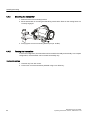
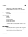
Measurement of liquids and gases
SITRANS F C Coriolis mass flowmeters are designed for measurement of a variety of liquids
and gases. The meters are multi-parameter devices offering accurate measurement of mass
flow, volume flow, density, temperature and fraction, including industry-specific fractions.
Main applications
The main applications of the Coriolis flowmeter can be found in all industries, such as:
● Chemical & Pharma: detergents, bulk chemicals, acids, alkalis, pharmaceuticals, blood
products, vaccines, insulin production
● Food & Beverage: dairy products, beer, wine, soft drinks, °Brix/°Plato, fruit juices and pulps,
bottling, CO2 dosing, CIP/SIP-liquids, mixture recipe control
● Automotive: fuel injection nozzle & pump testing, filling of AC units, engine consumption,
paint robots
● Oil & Gas: filling of gas bottles, furnace control, test separators
● Water & Waste Water: dosing of chemicals for water treatment
Note
Use in a domestic environment
This is a Class A Group 1 equipment intended for use in industrial areas.
In a domestic environment this device may cause radio interference.
SITRANS FC430 with HART
Operating Instructions, 06/2012, A5E03361511-03
25
Description
3.1 System configuration
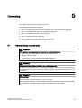
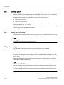
3.1
System configuration
The Coriolis flowmeter can be used in a number of system configurations:
● as a field mounted transmitter and display supplied only with the necessary auxiliary power
● as part of a complex system environment, for example SIMATIC S7
26
SITRANS FC430 with HART
Operating Instructions, 06/2012, A5E03361511-03
Description
3.2 Design
3.2
Design
Versions
The SITRANS FC430 flowmeter uses the Coriolis principle to measure flow and is available
in a remote and a compact version.
SITRANS FC430 with HART
Operating Instructions, 06/2012, A5E03361511-03
27
Description
3.2 Design
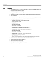
● Compact version: One single mechanical unit where the transmitter is directly mounted on
the sensor.
/
● Remote version: Transmitter and sensor installed separately. The remote system is
composed of SITRANS FCS400 sensor unit remotely connected to a SITRANS FCT030
transmitter. Directly mounted on the FCS400 sensor, its Digital Sensor Link (DSL) performs
the signal processing of all measured signals in the sensor. The 4-wire connection between
the transmitter and the sensor provides power and high-integrity digital communication
between the DSL and the transmitter.
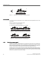
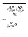
Compact versions
Figure 3-2
Remote version - M12 connection
/
Figure 3-1
28
SITRANS FC430 with HART
Operating Instructions, 06/2012, A5E03361511-03
Description
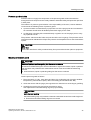
/
3.2 Design
Figure 3-3
Remote version - terminated cable
Sensor design
All primary process measurement of mass and volume flow, density and process temperature
are made in the DSL.
The FCS400 sensor is provided with two parallel bent tubes welded directly to the process
connections at each end via a manifold. The FCS400 sensor is available in a non-safe and an
intrinsically safe (IS) design.
The sensors are available in AISI 316L stainless steel. The enclosure is made of AISI 304
stainless steel and has a pressure rating of 20 bar (290 psi) for DN 15 to DN 50 and 17 bar
(247 psi) for DN 80.
The sensor enclosure can be equipped with a pressure guard or flushed with dry inert gas at
the threaded ports for non-hazardous applications only.
Note
Ex certification requires that the threaded ports always remain closed.
In the remote configuration, the sensor front end (DSL) is available in an aluminum enclosure
with an ingress protection grade of IP67/NEMA 4X. It has a 4-wire M12 cable connection for
communication and power supply.
SITRANS FC430 with HART
Operating Instructions, 06/2012, A5E03361511-03
29
Description
3.2 Design
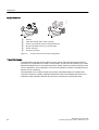
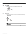
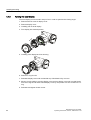
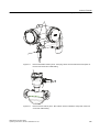
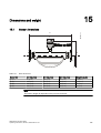
/
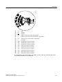
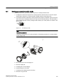
Sensor overview
①
②
③
④
⑤
⑥
Lid-lock
Cable feed-through (M12 socket or gland)
Sensor front end (DSL) (Remote configuration only)
Plug and threaded port for e.g. pressure guard
Sensor enclosure
Process connections
Figure 3-4
Overview, remote and compact configuration
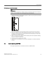
Transmitter design
The transmitter reads the primary values from the sensor and calculates derived values. It
provides four configurable I/Os, HART communication, and a local user interface (LUI). It also
adds functionalities such as corrected volume flow, density, fractions, totalizers, dosing, access
control, diagnostics, and configuration. The local user interface consists of a display and four
buttons for user interaction.
The transmitter has a modular design with discrete, replaceable electronic modules and
connection boards to maintain separation between functions and facilitate field service. All
modules are fully traceable and their provenance is included in the transmitter setup.
30
SITRANS FC430 with HART
Operating Instructions, 06/2012, A5E03361511-03
Description
3.2 Design
Transmitter exploded view
D
E
D
/
E
①
②
③
④
⑤
⑥
⑦
⑧
⑨
⑩
⑪
Display cover
Local user interface (LUI)
Connector for LUI
SD card (SensorFlash)
DIP switch (for custody transfer)
DIP switch (for HART)
LUI port
USB service port
Transmitter cassette
Heatsink cover for power supply module
Cable entry
Figure 3-5
⑫
⑬
⑭
⑮
⑯
⑰
⑱
⑲a
⑲b
⑳a
⑳b
Transmitter housing
Terminal space
Power supply terminal protection cover
Lid for terminal connections
Wiring tool
I/O cassette (optional)
I/O configuration keys (optional)
M12 socket
Terminal housing
Sensor module (compact version)
Sensor module (remote version)
Transmitter exploded view
SITRANS FC430 with HART
Operating Instructions, 06/2012, A5E03361511-03
31
Description
3.3 Features
3.3
Features
● The SITRANS FC430 can be used as HART slave in operation on SIEMENS SIMATIC S7/
PCS7 or third party automation systems
● Available in compact and remote design
● Full graphical Local User Interface (LUI)
● SensorFlash (SD card) for memory backup and documentation storage (certificates etc.)
● One current output
– Channel 1: Current output with HART (can be used for safety critical applications level
SIL 2 with one flowmeter or SIL 3 with dual-redundant flowmeters)
● Three optional input/output channels:
– Channel 2: Signal output; can be parameterized for:
Current output (0/4-20 mA)
Pulse output
Frequency output
One-stage dosing output
Two-stage dosing output
Alarm, status, flow direction
– Channels 3 and 4: Signal output (as channel 2)
Pulse or frequency redundancy mode (only channel 3)
– Channels 3 and 4: Relay output; can be parameterized as:
One-stage dosing output
Two-stage dosing output
Alarm, status, flow direction
– Channels 3 and 4: Signal input; can be parameterized as:
Dosing control
Totalizer control (resetting of totalizers)
Zero adjustment
Setting or freezing a frequency at the digital outputs if these are set to 'Frequency'
● Current, frequency, and pulse outputs with configurable fail safe mode
● HART communication interface (HART 7.2)
● High immunity against process noise
● Fast response to step changes in flow
● High update rate (100 Hz) on all process values
32
SITRANS FC430 with HART
Operating Instructions, 06/2012, A5E03361511-03
Description
3.3 Features
● Measurement of:
– Massflow
– Volumeflow
– Corrected volumeflow (including normalized gas flows)
– Density
– Process media temperature
– Fraction A (massflow or volumeflow)
– Fraction B (massflow or volumeflow)
– Fraction A %
– Fraction B %
● Configurable upper and lower alarms and warning limits for all process values
● Independent low flow cut-off settings for massflow and volumeflow
● Automatic zero-point adjustment
● Process noise damping using digital signal processing (DSP).
● Three totalizers for summation of massflow, volumeflow and corrected volumeflow,
depending on setting, of:
– Massflow measurement
– Volumeflow measurement
– Fraction A and B measurement (massflow or volumeflow)
– Corrected volumeflow
● Empty pipe monitoring
● Simulation of process values:
– Massflow
– Volumeflow
– Corrected volumeflow
– Density
– Process media temperature
– Fraction A %
– Fraction B %
– Frame temperature
● Simulation of all outputs
● Simulation and suppression of alarms
● Comprehensive diagnostics (NAMUR or Siemens standard) for troubleshooting and sensor
checking
● Firmware update
● Use in hazardous locations according to specification
SITRANS FC430 with HART
Operating Instructions, 06/2012, A5E03361511-03
33
Description
3.4 HART Communication Interface
3.4
HART Communication Interface
System communication
Table 3-1
HART protocol identification data
Manufacturer ID
42 (2A Hex)
Manufacturer ID parameter
Device type
34 (22 Hex)
Device type parameter
HART protocol revision
7.2
HART protocol revision parameter
Device revision
1
Device revision parameter
Note: Version numbers and other references shown above are typical or example values.
Device description files
Available EDD drivers:
● SIMATIC PDM
● FDT/DTM
● AMS suite
● 375 Field Communicator
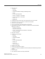
The drivers can be downloaded here:
Download EDD drivers (http://www.siemens.com/flowdocumentation)
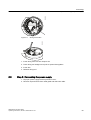
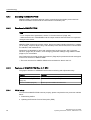
Configuration of the HART polling address
The HART address can be set either via hardware (DIP switch) or via software (LUI or SIMATIC
PDM).
2))
21
Figure 3-6
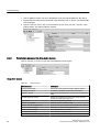
)&
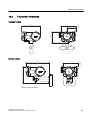
The DIP switch is located on the transmitter cassette, see position ⑥ "Transmitter exploded
view" in "Design" (Page 31).
HART slave address switch
● Configuration via DIP switch (HW polling address)
Set "1 to 15" on the DIP switch if you wish to set a fixed (hardware-defined) HART polling
address (SW polling address will be ignored). The configured HW polling address can be
read via LUI in menu item 4.2.
● Configuration via LUI or SIMATIC PDM (SW polling address)
Disable the HW polling address by setting all switches to "OFF" on the HART DIP switch.
The device starts up with default slave address = 0. The SW polling address can be changed
to "0 to 63" via LUI (menu item 4.1) or SIMATIC PDM
DIP switch configuration
34
SITRANS FC430 with HART
Operating Instructions, 06/2012, A5E03361511-03
Description
3.4 HART Communication Interface
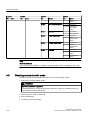
Table 3-2
HW polling address
Address
Switch 1
Switch 2
Switch 3
Switch 4
0
0
0
0
0
1
1
0
0
0
2
0
1
0
0
3
1
1
0
0
4
0
0
1
0
5
1
0
1
0
6
0
1
1
0
7
1
1
1
0
8
0
0
0
1
9
1
0
0
1
10
0
1
0
1
11
1
1
0
1
12
0
0
1
1
13
1
0
1
1
14
0
1
1
1
15
1
1
1
1
0: OFF; 1: ON
Mapping of measured process variables
The assignment of the measured process values to HART device variables (PV - primary
variable; SV - secondary variable; TV - tertiary variable; and QV - quaternary variable) can be
modified and assigned as desired via local user interface or via HART interface using SIMATIC
PDM.
PV: The process value assigned to current output 1 (LUI menu item 2.4.1.1) is automatically
assigned to PV.
● Measured values for PV
– Mass flow
– Volume flow
– Density
SV, TV, QV: Freely selectable (LUI menu item 4.6) from the list below.
SITRANS FC430 with HART
Operating Instructions, 06/2012, A5E03361511-03
35
Description
3.4 HART Communication Interface
● Measured values for SV, TV and QV
– Massflow
– Volumeflow
– Density
– Medium temperature
– Volume flow corrected
– Fraction A mass flow
– Fraction A volume flow
– Fraction B mass flow
– Fraction B volume flow
– Fraction A %
– Fraction B %
– Totalized value of totalizers 1, 2 or 3
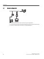
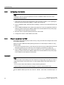
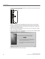
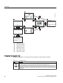
Communication is via the HART protocol, using:
● HART Communicator (load 230 to 500 Ω)
● PC with HART modem, on which appropriate software is installed, for example
SIMATIC PDM (load 230 to 500 Ω)
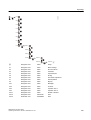
● Control system which can communicate via the HART protocol, for example SIMATIC PCS7
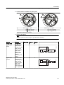
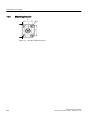
1
①
②
③
Figure 3-7
36
SIMATIC PLC system with HART interface
PC with SIMATIC PDM or similar application
HART modem
Possible system configurations
SITRANS FC430 with HART
Operating Instructions, 06/2012, A5E03361511-03
Description
3.5 Theory of operation
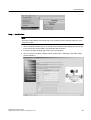
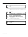
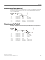
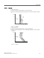
3.5
Theory of operation
The Coriolis principle of measurement
The flow measurement is based on the Coriolis law of motion. Particles moving in a rotating /
oscillating system will resist imposed oscillations in a manner consistent with their mass and
velocity (momentum). Oscillation produced by a Coriolis flowmeter where the process media
is accelerated around bends results in phase distortions of the measuring tubes.
The SITRANS F C sensors are energized by an electromagnetic driver circuit which oscillates
the pipes at their resonant frequency. Two pickups are placed symmetrically on either side of
the driver to provide position signals for digital processing.
When the media flows through the sensor, Coriolis force will act on the measuring tubes and
cause deflection which can be measured as a phase shift between Pickup 1 and Pickup 2.
The phase shift is proportional to the mass flowrate.
)UHTXHQF\à 'HQVLW\
7LPH à 0$66IORZ
3LFNXS
3LFNXS
The frequency (or period) of the vibration is a direct function of the process media density.
The frequency and amplitude of the driver is regulated to ensure a stable output from the 2
pickups. The temperature of the sensor tubes is measured to provide accurate compensation
for changes in the material stiffness. As a result the process media temperature is also
accurately measured.
The flow proportional phase signal from the pickups, the temperature measurement and the
driver frequency enable calculation and reporting of mass, density, volume, and temperature.
Digital signal processing (DSP)
The analog to digital conversion takes place in an ultra low noise sigma delta converter with
high signal resolution. With fast digital signal processing massflow and density values are
calculated using a patented DFT technology (Discrete Fourier Transformation). The
combination of this patented DFT technology and the fast DSP enables short response time
(< 10 ms) to changes in the measured values.
SITRANS FC430 with HART
Operating Instructions, 06/2012, A5E03361511-03
37
Description
3.5 Theory of operation
The built-in noise filter is configurable and can be used for improving the performance of the
flowmeter, in case the installation and application conditions are not ideal. Typical process
noise such as gas bubbles (two-phase-flow) can be reduced through the filter functions.
38
SITRANS FC430 with HART
Operating Instructions, 06/2012, A5E03361511-03
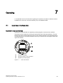
Installing/mounting
4.1
4
Introduction
SITRANS F flowmeters with minimum IP67/NEMA 4X enclosure rating are suitable for indoor
and outdoor installations.
● Make sure that specifications for process pressure (PS) and media temperature (TS) plus
ambient temperature that are indicated on the device nameplate / label will not be
exceeded.
WARNING
Installation in hazardous location
Special requirements apply to the location and interconnection of sensor and transmitter.
See "Installation in hazardous locations" (Page 20)
4.2
Strong vibrations
CAUTION
Strong vibrations
Damage to device.
● In plants with strong vibrations, mount the transmitter in a low vibration environment away
from the sensor.
4.3
Sensor installation
4.3.1
Installation safety precautions
WARNING
High pressure hazard
In applications with working pressures/media that can be dangerous to people, surroundings,
equipment or others in case of pipe fracture, we recommend that special precautions such
as special placement, shielding or installation of a pressure guard or a safety valve are taken
when the sensor is mounted.
SITRANS FC430 with HART
Operating Instructions, 06/2012, A5E03361511-03
39
Installing/mounting
4.3 Sensor installation
WARNING
Exceeded maximum permissible operating pressure
Danger of injury or poisoning.
The maximum permissible operating pressure depends on the device version. The device
can be damaged if the operating pressure is exceeded. Hot, toxic and corrosive process
media could be released.
● Make sure that the device is suitable for the maximum permissible operating pressure of
your system. Refer to the information on the nameplate and/or in "Rated operating
conditions (Page 178)".
CAUTION
Hot surfaces resulting from hot process media
Danger of burns resulting from surface temperatures above 70 °C (155 °F).
● Take appropriate protective measures, for example contact protection.
● Make sure that protective measures do not cause the maximum permissible ambient
temperature to be exceeded. Refer to the information in Chapter "Rated operating
conditions (Page 178)".
CAUTION
External stresses and loads
Damage to device by severe external stresses and loads (e.g. thermal expansion or pipe
tension). Process media can be released.
● Prevent severe external stresses and loads from acting on the device.
WARNING
Wetted parts unsuitable for the process media
Danger of injury or damage to device.
Hot, toxic and corrosive media could be released if the process medium is unsuitable for the
wetted parts.
● Ensure that the material of the device parts wetted by the process medium is suitable for
the medium. Refer to the information in "Technical data" (Page 180).
40
SITRANS FC430 with HART
Operating Instructions, 06/2012, A5E03361511-03
Installing/mounting
4.3 Sensor installation
Note
Material compatibility
Siemens can provide you with support concerning selection of sensor components wetted
by process media. However, you are responsible for the selection of components. Siemens
accepts no liability for faults or failures resulting from incompatible materials.
4.3.2
Determining a location
CAUTION
Do not install the sensor in the vicinity of strong electromagnetic fields, for example near
motors, variable frequency drives, transformers etc.
Upstream / downstream
● No pipe run requirements, that is straight inlet/outlet sections are not necessary.
● Avoid long drop lines downstream from the sensor to prevent process media separation
causing air / vapour bubbles in the tube (min. back pressure: 0.2 Bar).
● Avoid installing the sensor immediately upstream of a free discharge in a drop line.
SITRANS FC430 with HART
Operating Instructions, 06/2012, A5E03361511-03
41
Installing/mounting
4.3 Sensor installation
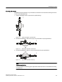
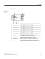
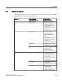
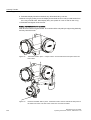
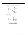
Location in the system
The optimum location in the system depends on the application:
● Liquid applications
Gas or vapor bubbles in the fluid may result in erroneous measurements, particularly in the
density measurement.
– Do not install the flowmeter at the highest point in the system, where bubbles will be
trapped.
– Install the flowmeter in low pipeline sections, at the bottom of a U-section in the pipeline.
Figure 4-1
Liquid applications, wrong location with trapped air/gas
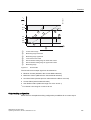
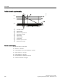
● Gas applications
Vapor condensation or oil traces in the gas may result in erroneous measurements.
– Do not install the flowmeter at the lowest point of the system
– Install a filter.
Figure 4-2
4.3.3
Gas applications, wrong location with trapped oil
Orientation of the sensor
Flow direction
The calibrated flow direction is indicated by the arrow on the sensor. Flow in this direction will
be indicated as positive by default. The sensitivity and accuracy of the sensor is identical with
reverse flow.
The indicated flow direction (positive/ negative) is configurable.
CAUTION
The sensor must always be completely filled with process media in order to measure
accurately.
42
SITRANS FC430 with HART
Operating Instructions, 06/2012, A5E03361511-03
Installing/mounting
4.3 Sensor installation
Orienting the sensor
SITRANS FCS400 operates in any orientation, but Siemens recommends orienting the sensor
in one of the following ways:
/
1. Vertical installation with an upwards flow (self-draining)
Figure 4-3
Vertical orientation, upwards flow
/
2. Horizontal installation, tubes down (only recommended for liquid applications)
Figure 4-4
Horizontal orientation, tubes down
/
3. Horizontal installation, tubes up (only recommended for gas applications)
Figure 4-5
Horizontal orientation; tubes up
Note
Hygienic applications
In 3A and EHEDG certified hygienic applications the flowmeter must be installed vertically
as shown in 1.
SITRANS FC430 with HART
Operating Instructions, 06/2012, A5E03361511-03
43
Installing/mounting
4.3 Sensor installation
Installation in a drop line
/
Installation in a drop line is only recommended if a pipeline reduction or orifice with a smaller
cross-section can be installed to create back-pressure and prevent the sensor from being
partially drained while measuring.
①
②
Back pressure orifice
On / off valve
Figure 4-6
4.3.4
Installation in drop line
Mounting the sensor
NOTICE
Incorrect mounting
The device can be damaged, destroyed, or its functionality impaired through improper
mounting.
● Before installing ensure there is no visible damage to the device.
● Make sure that process connectors are clean, and suitable gaskets and glands are used.
● Mount the device using suitable tools. Refer to the information in "Technical data"
(Page 185) , for example installation torques requirements.
44
SITRANS FC430 with HART
Operating Instructions, 06/2012, A5E03361511-03
Installing/mounting
4.3 Sensor installation
WARNING
Unsuitable connecting parts
Danger of injury or poisoning.
In case of improper mounting hot, toxic and corrosive process media could be released at
the connections.
● Ensure that connecting parts (such as flange gaskets and bolts) are suitable for connection
and process media.
● Install the sensor in rigid pipelines in order to support the weight of the meter.
● Center the connecting pipelines axially in order to assure a stress-free installation.
● Install two supports or hangers symmetrically and stress-free on the pipeline in close
proximity to the process connections.
Handling
Note
Compact versions
Never lift the flowmeter using the transmitter housing, that is always lift the sensor body.
Avoid vibrations
● Make sure that any valves or pumps upstream of the sensor do not cavitate and do not
send vibration into the sensor.
)&
● Decouple vibrating pipeline from the flow sensor using flexible tube or couplings
Figure 4-7
Non-flexible pipes not recommended in vibrating environment
SITRANS FC430 with HART
Operating Instructions, 06/2012, A5E03361511-03
45
Installing/mounting
)&
4.3 Sensor installation
Figure 4-8
Flexible pipes recommended in vibrating environment
Avoid cross talk
If operating more than one flowmeter in one or multiple interconnected pipelines there is a risk
of cross talk.
Prevent cross talk in one of the following ways:
● Mount sensors on separate frames
)&
● Decouple the pipeline using flexible tube or couplings
High risk of cross talk when using non-flexible pipes
Figure 4-10
Low risk of cross talk when using flexible pipes
)&
Figure 4-9
4.3.5
Mounting a pressure guard
The sensor enclosure is supplied with two G½" purge ports. These ports can for example be
used for a pressure guard, which can be connected to an automatic shut off valve to stop the
flow in case of sensor pipe fracture. The pressure guard can only be applied in non-hazardous
locations. Opening either of the purge ports will void any Ex rating for the sensor.
The AISI 304 / EN 1.4301 exterior enclosure is rated to approximately 20 bar static pressure
to contain spilt process media in the event of a tube break. However it is not intended to contain
high pressure or corrosive fluids and precautions must be taken in applications where vibrating
tube failure is probable and may cause damage.
46
SITRANS FC430 with HART
Operating Instructions, 06/2012, A5E03361511-03
Installing/mounting
4.3 Sensor installation
Pressure guard selection
Siemens does not supply the components of the pressure guard solution because the
arrangement and components are closely related to individual safety and protection practices
in each place.
The selection of pressure guard solution is the responsibility of the user, however Siemens
recommends the following forms of pressure guard:
● A pressure switch screwed directly or piped into one of the purge ports and connected to
an automatic shutoff valve will disable pressurized supply to the meter.
● A relief valve or bursting disc screwed directly or piped to one of the purge ports to carry
any spilt fluid to drain.
The pressure switch and relief valve set point should be 2-3 bar gauge. The pressure switch
should be rated to withstand the full process pressure and temperature for a short time without
rupture.
CAUTION
Drain flow
Ensure the drain flow is safely contained away from personnel and other plant or equipment.
Mounting of pressure guard
CAUTION
Moisture, liquids or particles getting into the sensor enclosure
All sensors are filled with argon to avoid condensation. Ingress of moisture, liquids or particles
into the sensor may influence the measurement and in worst case inhibit the measuring
function.
● Avoid moisture, liquids or particles getting into the sensor enclosure
Install a pressure guard as follows:
1. Place the sensor in a dry, clean place and leave it to acclimatize until it reaches ambient
temperature, preferred 20°C (68°F) with low humidity (at least below 50% RH).
2. Orient the sensor with the purge ports uppermost to minimize loss of the Argon gas filling.
3. Carefully remove the plug and mount the pressure guard.
Use replacement soft metal sealing rings for proper sealing
CAUTION
Lack of proper sealing
Soft metal sealing rings only maintain a hermetic seal within the enclosure with single use.
● Ensure that soft metal sealing rings are not reused.
SITRANS FC430 with HART
Operating Instructions, 06/2012, A5E03361511-03
47
Installing/mounting
4.4 Transmitter installation
4. Make sure that the pressure guard does NOT touch any of the parts inside the sensor.
Maximum of 20 mm (0.79") insertion can be accommodated.
5. Check that the pressure guard has been correctly mounted and thoroughly tightened
(torque: 80 Nm).
WARNING
Operation in proximity with pressure guards
Prevent personal injuries by assuring that operation in close proximity with pressure
guards cannot take place.
4.4
Transmitter installation
4.4.1
Introduction
This chapter describes how to install the transmitter on a wall or pipe (remote configurations
only). The chapter further describes how to turn the transmitter or the local display in order to
optimize the viewing angle.
The following installation steps must be carried out:
1. Install the mounting bracket (Page 49) on a wall or pipe.
2. Install the transmitter on the mounting bracket (Page 50).
3. Turn the transmitter (Page 50) and/or turn the local display (Page 52) (optional).
CAUTION
Aggressive atmospheres
Damage to device through penetration of aggressive vapors.
● Ensure that the device is suitable for the application.
CAUTION
Direct sunlight
Device damage.
The device can overheat or materials become brittle due to UV exposure.
● Protect the device from direct sunlight.
● Make sure that the maximum permissible ambient temperature is not exceeded. Refer to
the information in "Technical data" (Page 178).
48
SITRANS FC430 with HART
Operating Instructions, 06/2012, A5E03361511-03
Installing/mounting
4.4 Transmitter installation
4.4.2
Wall mounting
1. Prepare holes with aid of mounting bracket, see "Mounting bracket" (Page 202).
2. Fasten mounting bracket with black cushion pad to wall (torque 10 Nm).
4.4.3
Pipe mounting
1. Mount mounting bracket with cushion pad on pipe using fastening brackets/U-bolts and
supplied pipe adaptor. Note: U-bolts and other miscellaneous hardware are not supplied
with the flowmeter.
2. Tighten nuts (torque: 10 Nm).
Note
Hygienic applications
If the device is wall or pipe-mounted in a hygienic application, always use domed nuts.
SITRANS FC430 with HART
Operating Instructions, 06/2012, A5E03361511-03
49
Installing/mounting
4.4 Transmitter installation
4.4.4
Mounting the transmitter
1. Remove screw from mounting bracket.
2. Mount transmitter on mounting bracket taking care that the flutes on the mating faces are
correctly engaged.
3. Firmly tighten screw on mounting bracket (torque: 25 Nm).
4.4.5
Turning the transmitter
In a remote configuration, the transmitter can be turned horizontally and vertically. In a compact
configuration, the transmitter can be turned horizontally only.
Horizontal rotation
1. Unscrew cap from lock screw.
2. Loosen lock screw at transmitter pedestal using 5 mm Allen key.
50
SITRANS FC430 with HART
Operating Instructions, 06/2012, A5E03361511-03
Installing/mounting
4.4 Transmitter installation
r
/
3. Carefully rotate transmitter into desired position.
r
4. Firmly tighten lock screw (torque: 10 Nm).
5. Replace cap onto lock screw (torque: 10 Nm).
Vertical rotation
1. Loosen locking cap at end of mounting bracket by three turns.
2. Carefully loosen and rotate transmitter into desired position (15° steps).
3. Firmly tighten locking cap (torque: 25 Nm).
SITRANS FC430 with HART
Operating Instructions, 06/2012, A5E03361511-03
51
Installing/mounting
4.4 Transmitter installation
4.4.6
Turning the local display
The local display can be turned in steps of 30° in order to optimize the viewing angle.
1. Remove lid lock screw of display cover.
2. Remove display cover.
3. Carefully pull out local display.
4. Turn display into desired position.
5. Carefully push display back into housing.
6. Remove o-ring from lid.
7. Reinstate display cover until mechanical stop. Wind back lid by one turn.
8. Mount o-ring by pulling it over the display cover and turn display cover until you feel friction
from the o-ring on both sides. Wind display cover by one quarter of a turn to seal on the oring.
9. Reinstate and tighten lid lock screw.
52
SITRANS FC430 with HART
Operating Instructions, 06/2012, A5E03361511-03
5
Connecting
This chapter describes how to wire up the device.
The following steps must be carried out:
● Step 1: Connecting the sensor and the transmitter (only remote versions) (Page 56)
● Step 2: Preparing for the transmitter connections (Page 59)
● Step 3: Connecting the power supply (Page 63)
● Step 4: Connecting the I/Os (Page 65)
● Step 5: Finishing the transmitter connection (Page 69)
5.1
General safety requirements
WARNING
The pertinent regulations must be observed for electrical installation.
● Never install the device with the mains voltage switched on!
● Danger of electric shock!
● If the housing is under voltage (power supply), the cover may be unscrewed by qualified
personnel only, except in classified hazardous locations.
WARNING
Mains supply from building installation overvoltage category 2
A switch or circuit breaker (max. 15 A) must be installed in close proximity to the equipment
and within easy reach of the operator. It must be marked as the disconnecting device for the
equipment.
WARNING
Wire insulation
Required cable: minimum AWG16 or 1.5 mm2 Cu wire.
The insulation between the connected mains supply and 24 V AC/DC supply for the flowmeter
must at least be rated with double or reinforced insulation at mains voltage.
SITRANS FC430 with HART
Operating Instructions, 06/2012, A5E03361511-03
53
Connecting
5.3 Cable requirements
5.2
Wiring in hazardous locations
Hazardous area applications
Special requirements apply to the location and interconnection of sensor and transmitter. See
"Installation in hazardous locations" (Page 20).
WARNING
Terminal box
Before opening the terminal box check that:
● No explosion hazard exists
● All connection leads are potential free
WARNING
Grounding
The mains protective earth wire must be connected to the PE terminal.
Note
Output cables
If long cables are used in noisy environments, it is recommended to use screened cables.
5.3
Cable requirements
Cable specifications
● Only use cables with at least the same degree of protection as the sensor to install the
sensor. It is recommended to use cables supplied by Siemens A/S, Flow Instruments:
– blue cables for installation in hazardous areas
– gray cables for installation in non-hazardous areas
Further information on Siemens-supplied cables, see "Technical Data" (Page 183).
● The wire length inside the terminal box, from the cable gland to the terminals, must be kept
as short as possible. Wire loops in the terminal box must be avoided.
● To guarantee the IP67 degree of protection, ensure that both ends of the cables are given
equivalent protection from ingress of moisture.
54
SITRANS FC430 with HART
Operating Instructions, 06/2012, A5E03361511-03
Connecting
5.4 Safety notes for connecting
WARNING
Cable requirements
Cables must be suitable for the temperature (at least 70 °C) and be flammability-rated to at
least V-2.
WARNING
Unprotected cable ends
Danger of explosion through unprotected cable ends in hazardous areas.
● Protect unused cable ends in accordance with IEC/EN 60079-14.
5.4
Safety notes for connecting
WARNING
Skills
Only qualified personnel may carry out work on the electrical connections.
Use in hazardous locations
Before accessing the sensor terminal space and application terminal space check that:
● No explosion hazard exists
● A safe access permission certificate has been issued by plant operations management
● All connection leads are potential free
WARNING
Hazardous locations
Observe the type examination certificates or the test certifications applicable in your
country if you use transmitters as category 1/2 equipment.
WARNING
Commissioning
Only commission the device after the device has been properly connected and, if required,
closed.
SITRANS FC430 with HART
Operating Instructions, 06/2012, A5E03361511-03
55
Connecting
5.5 Step 1: Connecting the sensor and the transmitter
5.5
Step 1: Connecting the sensor and the transmitter
The following only applies to remote configurations.
Wiring sensor and transmitter (M12)
The sensor is provided with a preformed cable terminated with M12 style stainless steel
weather-proof plugs.
The cable screen is physically and electrically terminated within the body of the plug.
Take care when handling the cable and passing it through cable ducting that the plug is not
subjected to excessive tension (pulling) as the internal connections may be disengaged.
Note
Never pull the cable by the plug - only by the cable itself.
1. Connect sensor using the supplied 4-wire cable with M12 connectors.
Note
Grounding
The sensor cable screen is mechanically connected to the grounding terminal (PE), only
when the M12 plug is correctly tightened.
Wiring sensor and transmitter (sensor terminal spaces)
PP
PP
PP
%OXH
/
A: Prepare the cable by stripping it at both ends.
:KLWH
<HOORZ
2UDQJH
Figure 5-1
Cable end
B: Connecting within the sensor terminal spaces
1. Remove lock screw and remove lid.
2. Remove one of the blind plugs and fit cable gland.
3. Remove cap and ferrule from cable gland and slide onto cable.
4. Push cable through open gland; anchor cable screen and wires with clamp bar.
5. Connect wires to terminals according to list below.
56
Terminal number
Description
Wire color (Siemens)
1
+15 V DC
Orange
2
0 V DC
Yellow
SITRANS FC430 with HART
Operating Instructions, 06/2012, A5E03361511-03
Connecting
5.5 Step 1: Connecting the sensor and the transmitter
Terminal number
Description
Wire color (Siemens)
3
B
White
4
A
Blue
1. Assemble and tighten cable gland.
2. Remove o-ring from lid.
3. Reinstate lid and screw in until mechanical stop. Wind back lid by one turn.
4. Mount o-ring by pulling it over the lid and tighten lid until you feel friction from the o-ring on
both sides. Wind lid by one quarter of a turn to seal on the o-ring.
5. Reinstate and tighten lid lock screw
Connecting sensor DSL
1. Remove lock screw and remove DSL lid.
2. Undo the flexible strap.
3. Disconnect sensor connection from DSL cassette.
4. Loosen mounting screw using a TX10 Torx driver and remove DSL cassette from housing.
5. Remove cap and ferrule from cable gland and slide onto cable.
6. Push cable through open gland; anchor cable screen and wires with clamp bar.
7. Remove terminal block from DSL cassette.
8. Connect wires to terminals according to list below.
Terminal number
Description
Wire color (Siemens cable)
1
+15 V DC
Orange
2
0 V DC
Yellow
3
B
White
4
A
Blue
SITRANS FC430 with HART
Operating Instructions, 06/2012, A5E03361511-03
57
Connecting
5.5 Step 1: Connecting the sensor and the transmitter
1. Reinstall DSL cassette including mounting screw.
2. Connect sensor connection and sensor cable.
3. Restore flexible strap around all wires.
4. Assemble and tighten cable gland.
5. Remove o-ring from DSL lid.
6. Reinstate lid and screw in until mechanical stop. Wind back lid by one turn.
7. Mount o-ring by pulling it over the DSL lid and tighten lid until you feel friction from the oring on both sides. Wind lid by one quarter of a turn to seal on the o-ring.
8. Reinstate and tighten lid lock screw.
WARNING
Improper laying of shielded cables
Danger of explosion through compensating currents between hazardous area and the nonhazardous area.
● Only ground shielded cables that run into the hazardous area at one end.
● If grounding is required at both ends, use an equipotential bonding conductor
58
SITRANS FC430 with HART
Operating Instructions, 06/2012, A5E03361511-03
Connecting
5.7 Step 2: Preparing for the transmitter connections
WARNING
Insufficient isolation of non-intrinsically safe and intrinsically safe circuits
Danger of explosion in areas subject to explosion hazard.
● When connecting intrinsically safe and non-intrinsically safe circuits ensure that isolation
is carried out properly in accordance with IEC / EN 60079-14.
● Make sure that you observe the test certification applicable in your country.
5.6
Lack of equipotential bonding
WARNING
Lack of equipotential bonding
Danger of explosion through compensating currents or ignition currents through lack of
equipotential bonding.
● Ensure that the device is potentially equalized.
5.7
Step 2: Preparing for the transmitter connections
WARNING
Non-hazardous locations only
As long as the device is energized, the lid of the housing on the sensor connection area may
only be opened by qualified personnel.
Before removing the terminal cover, the auxiliary power must be switched off from all poles.
Following installation, the terminal cover must be screwed back on again.
SITRANS FC430 with HART
Operating Instructions, 06/2012, A5E03361511-03
59
Connecting
5.7 Step 2: Preparing for the transmitter connections
1. Remove blind plugs where required and mount cable glands.
1
2
3
①
②
③
Input/output connection (channels 2 to 4)
Power supply connection
Current output/HART connection (channel 1)
2. Remove lid lock screw for terminal connections lid.
3. Remove lid for terminal connections.
A label with a diagram showing the terminal connections is placed at the back of the terminal
connections lid.
60
SITRANS FC430 with HART
Operating Instructions, 06/2012, A5E03361511-03
Connecting
)&
5.7 Step 2: Preparing for the transmitter connections
①
②
③
④
⑤
⑥
⑦
⑧
⑨
⑩
⑪
⑫
⑬
⑭
⑮
⑯
L/+
Line
N/-
Neutral
Ca+
Used in current output active configuration
C
Used in current output active and passive configuration
Cp-
Used in current output passive configuration
---
Not used
IO2+
Signal output channel 2 positive
IO2
Signal output channel 2 common
IO2-
Signal output channel 2 negative
IO3+
Input/output channel 3 positive
IO3
Input/output channel 3 common
Ground
IO3-
Input/output channel 3 negative
IO4+
Input/output channel 4 positive
IO4
Input/output channel 4 common
IO4-
Input/output channel 4 negative
For configuration if the inputs/outputs, see table in section "Step 4b: Connecting the inputs
and outputs (channels 2 to 4)" (Page 66).
SITRANS FC430 with HART
Operating Instructions, 06/2012, A5E03361511-03
61
Connecting
5.7 Step 2: Preparing for the transmitter connections
WARNING
Unsuitable cables and/or cable glands
Danger of explosion in hazardous areas.
● Only use suitable cables and cable glands complying with the requirements specified in
"Technical data" (Page 183).
● Tighten the cable glands in accordance with the torques specified in "Technical data"
(Page 185).
● When replacing cable glands use only cable glands of the same type.
● After installation check that the cables are seated firmly.
WARNING
Open cable inlet or incorrect cable gland
Danger of explosion in hazardous areas.
● Close the cable inlets for the electrical connections. Only use cable glands or plugs which
are approved for the relevant type of protection.
See also
Cables and cable entries (Page 183)
WARNING
Incorrect conduit system
Danger of explosion in hazardous areas as result of open cable inlet or incorrect conduit
system.
● In the case of a conduit system, mount a spark barrier at a defined distance from the
device input. Observe national regulations and the requirements stated in the relevant
approvals.
Wiring tool
Use the wiring tool for connecting the cables.
The wiring tool is located in the application terminal space.
62
SITRANS FC430 with HART
Operating Instructions, 06/2012, A5E03361511-03
Connecting
/
5.8 Step 3: Connecting the power supply
Wiring tool location
/
Figure 5-2
1. Insert wiring tool hook into receptor slot.
2. Press wiring tool wedge into top slot to spread clamp plates.
3. Insert wire.
4. Release wiring tool.
5.8
Step 3: Connecting the power supply
1. Flip open power supply terminal protection cover.
2. Remove cap and ferrule from cable gland and slide onto cable.
SITRANS FC430 with HART
Operating Instructions, 06/2012, A5E03361511-03
63
Connecting
5.8 Step 3: Connecting the power supply
3. Push cable through open gland and cable path.
4. Restore ferrule and tighten cap to lightly hold cable in place.
/
5. Connect ground to terminal and power to terminals L/+ and N/- using wiring tool in the
manner shown below at right.
1
2
3
L/+
N/-
DC connection
/
/
1
1
/
AC connection
Power: 100 to 240 V AC +10/-15%, 47 to 63 Hz
64
/
1
/
①
②
③
Power: 24 to 90 V DC +20/-20%
SITRANS FC430 with HART
Operating Instructions, 06/2012, A5E03361511-03
Connecting
5.10 Step 4a: Connecting the current output HART (channel 1)
1. Anchor cable with clamp bar.
2. Close and latch power supply terminal protection cover.
3. Tighten cable gland.
5.9
Missing PE/ground connection
WARNING
Missing PE/ground connection
Danger of electric shock.
Depending on the device version, connect the power supply as follows:
● Connecting terminals: Connect the terminals according to the terminal connection
diagram. First connect the PE/ground conductor.
5.10
Step 4a: Connecting the current output HART (channel 1)
Note
HART communication
It is recommended to use shielded cables for HART communication.
WARNING
Passive channels only
Channel 1 power supply must be separated from that for channels 2 to 4.
Signal return (or common) can be joined.
1. Remove cap and ferrule from cable gland and slide onto cable.
2. Push cable through open gland and cable path.
3. Restore ferrule and tighten cap to lightly hold cable in place.
4. Signal cable screen is folded back over outer sheath and grounded beneath cable clamp.
SITRANS FC430 with HART
Operating Instructions, 06/2012, A5E03361511-03
65
Connecting
5.11 Step 4b: Connecting the inputs and outputs (channels 2 to 4)
5. Connect wires to terminals using wiring tool.
6
5
5
4
Active current output
⑤
④
Passive current output
⑥
⑤
C
Ca+
C
8LQW
+
U0
Ca+
Cp-
C
,VLJQDO
,VLJQDO
8
+
8H[W
-
)&
Cp-
-
C
Passive current output
)&
Active current output
Cp-
Ca+
6. Tighten cable gland.
Note
Active or passive current output is preselected at ordering.
Note
Load
Current output (channel 1): < 500 Ω (HART ≥ 230 Ω)
5.11
Step 4b: Connecting the inputs and outputs (channels 2 to 4)
1. Remove cap and ferrule from cable gland and slide onto cable.
2. Push cable through open gland and cable path.
3. Restore ferrule and tighten cap to lightly hold cable in place.
4. Signal cable screen is folded back over outer sheath and grounded beneath cable clamp.
66
SITRANS FC430 with HART
Operating Instructions, 06/2012, A5E03361511-03
Connecting
5.11 Step 4b: Connecting the inputs and outputs (channels 2 to 4)
5. Connect wires to terminals using wiring tool.
13
12
12
11
Active current output
⑫
⑪
Passive current output
⑬
⑫
IO[3] (common)
IO[3]+ (active)
IO[3]- (passive)
IO[3] (common)
Termination example for channel 3
6. Tighten cable gland.
Note
Factory
configuration
Software
configuration
Channel 2 Channel
3
Channel
4
Signal output
Current Output
Pulse Output
Frequency Output
Status Output
X
X
IOXp-
IOXC
If Status Output:
Alarm Class
Alarm Item
Primary Valve
Dosing
Secondary Valve
Dosing
Signal output
Passive
Current Output
Pulse Output
Frequency Output
Status Output
8LQW
+
-
X
If Status Output:
Alarm Class
Alarm Item
One Stage Dosing
Two Stage Dosing
SITRANS FC430 with HART
Operating Instructions, 06/2012, A5E03361511-03
X
U0
,VLJQDO
IOXa+
X
IOXp-
IOXC
,VLJQDO
8
+
8H[W
-
)&
Active
X
)&
Active or passive current output is preselected at ordering.
IOXa+
67
Connecting
5.11 Step 4b: Connecting the inputs and outputs (channels 2 to 4)
Signal input
Start Dosing
Stop Dosing
Reset Totalizer 1
Reset Totalizer 2
Reset Totalizer 3
Reset All
Totalizers
Pause/Resume
dosing,
Force Output
Freeze Output
X
Start Dosing
Stop Dosing
Reset Totalizer 1
Reset Totalizer 2
Reset Totalizer 3
Reset All
Totalizers
Pause/Resume
dosing,
Force Output
Freeze Output
X
Alarm Class
Alarm Item
One Stage Dosing
Two Stage Dosing
X
Signal input
Passive
Relay output
Channel
4
X
IOXp-
IOXC
-
8LQW
+
U0
,VLJQDO
IOXa+
X
IOXp-
IOXC
,VLJQDO
8
+
8H[W
-
IOXa+
X
IOXp-
IOXC
)&
Active
Channel 2 Channel
3
)&
Software
configuration
)&
Factory
configuration
IOXa+
Normally open
Alarm Class
Alarm Item
One Stage Dosing
Two Stage Dosing
X
X
IOXp-
)&
Relay output
IOXC
IOXa+
Normally closed
Note
Load
Signal output: < 500 Ω
Relay output: 30 V AC/DC, 100 mA
68
SITRANS FC430 with HART
Operating Instructions, 06/2012, A5E03361511-03
Connecting
5.12 Step 5: Finishing the transmitter connection
5.12
Step 5: Finishing the transmitter connection
Connection check-up
1. Check individual wire installation by tugging firmly.
2. Firmly tighten cable glands and insert blanking plugs in unused cable entries.
3. Remove o-ring from lid.
4. Reinstate lid and screw in until mechanical stop. Wind back lid by one turn.
5. Mount o-ring by pulling it over the lid and tighten lid cover until you feel friction from the oring on both sides. Wind lid by one quarter of a turn to seal on the o-ring.
6. Reinstate and tighten lid lock screw where supplied.
7. Ensure that moisture does not penetrate to inside of electronics housing by creating a drip
loop (bend cables downward) immediately before cable glands.
Note
Loss of degree of protection
Damage to device if the enclosure is open or not properly closed. The degree of protection
specified on the nameplate or in "Technical data" (Page 180) is no longer guaranteed.
● Make sure that the device is securely closed.
SITRANS FC430 with HART
Operating Instructions, 06/2012, A5E03361511-03
69
Commissioning
6.1
6
General requirements
Before commissioning it must be checked that:
● The device has been installed and connected in accordance with the guidelines provided
in "Installing/mounting" (Page 39) and "Connecting" (Page 53).
● Device installed in hazardous area meets the requirements described in "Installation in
hazardous locations" (Page 20).
6.2
Warnings
CAUTION
If the sensor and the transmitter are ordered separately, a "Set To Default"routine must be
performed. This can be sone via SIMATIC PDM or via LUI in menu item 3.3.3.
WARNING
Certain parts inside the device carry dangerous high voltage. The housing must be closed
and grounded before switching the device on.
WARNING
The sensor connected to this device can be operated with high pressure and corrosive media.
Therefore improper handling of the device can lead to serious injuries and/or considerable
material damage.
WARNING
Commissioning and operation with pending error
If an error message appears, correct operation in the process is no longer guaranteed.
● Check the gravity of the error
● Correct the error
● If the device is faulty:
– Take the device out of operation.
– Prevent renewed commissioning.
SITRANS FC430 with HART
Operating Instructions, 06/2012, A5E03361511-03
71
Commissioning
6.3 Commissioning via LUI
6.3
Commissioning via LUI
6.3.1
Introduction
In this chapter it is described how to commission the device via the local user interface (LUI)
using the Quick Start menu.
For further information on how to operate the device via LUI, refer to "Operating; Local User
Interface (LUI)" (Page 93).
Recommendation
Before commissioning a basic knowledge of the local display and the menu structure should
be obtained. This is offered in the chapters
● "Local user interface (LUI)" (Page 93)
● "Navigating the menu" (Page 94)
Quick Start menu
The LUI includes a Quick Start menu with the most important parameters/menus for quick
configuration of the flowmeter.
6.3.2
Overview
Quick start steps
The quick start menu prompts for check or setup of the following parameters/menus:
● Flow Direction
● Process Noise Damping
● Massflow
● Volumeflow
● Density
● Fluid Temperature
● Fraction
● Totalizer 1
● Totalizer 2
72
SITRANS FC430 with HART
Operating Instructions, 06/2012, A5E03361511-03
Commissioning
6.3 Commissioning via LUI
● Totalizer 3
● Start Zero Point Adjustment
Note
Preconditions for zero point adjustment
Before a zero point adjustment is initiated, the pipe must be flushed, filled and at an
absolute flowrate of zero. Refer to "Zero point adjustment" (Page 74) for more details.
6.3.3
Quick Start
The following example describes a configuration in which the Process Noise Damping, the
Massflow and the Totalizer 1 settings are changed, and a Zero Point Adjustment is started.
Access Level
The access level is "User" (default PIN is 2457).
Process Noise Damping
The process noise damping is changed from "Duplex Pump" to "Triplex Pump".
Massflow
The unit is changed kg/s to kg/h; and the low flow cut-off is changed from 0 kg/h to 2 kg/h.
Totalizer 1
The direction is changed from positive to balanced.
Zero Point Adjustment
The zero point adjustment is started with default zero point adjustment settings.
SITRANS FC430 with HART
Operating Instructions, 06/2012, A5E03361511-03
73
Commissioning
)&66
6.3 Commissioning via LUI
6.3.4
Zero point adjustment
The flowmeter system is optimized through a zero point adjustment which is accessed via the
menu item 1.11 "Start Zero Point Adj." in the Quick Start menu.
74
SITRANS FC430 with HART
Operating Instructions, 06/2012, A5E03361511-03
Commissioning
6.4 Commissioning with PDM
Performing a zero point adjustment
Note
Preconditions
Before a zero point adjustment is initiated, the pipe must be flushed, filled and at an absolute
flowrate of zero preferably also at operating pressure and temperature.
/
1. Flush out any gases and obtain stable temperature conditions by running flow at operational
conditions for minimum 30 minutes.
Figure 6-1
Best practice zero point adjustment with a by-pass line and two shut-off devices
2. Close the outlet shut-off valve while maintaining the system pressure. If bypass flow is
necessary, open the bypass valve. If the pressure can be increased by 1 to 2 bars with
stopped flow, this should be applied.
3. Wait 1 to 2 minutes, for the system to settle, and then perform zero adjustment. Waiting
longer can change the temperature.
4. During the process a progress bar is visible.
5. At the end of the zero adjustment, the outcome is displayed as an offset and standard
deviation.
6.4
Commissioning with PDM
This chapter describes how to commission the device via SIMATIC PDM.
SITRANS FC430 with HART
Operating Instructions, 06/2012, A5E03361511-03
75
Commissioning
6.4 Commissioning with PDM
6.4.1
Operating via SIMATIC PDM
SIMATIC PDM is a software package used to commission and maintain process devices.
Further information can be found at: www.siemens.com/simatic-pdm.
6.4.2
Functions in SIMATIC PDM
Note
- For a complete list of parameters, see the "LUI menu structure" (Page 203).
- While the device is in PROGRAM mode the output remains fixed and does not respond to
changes in the device.
SIMATIC PDM monitors the process values, alarms and status signals of the device. It allows
you to display, compare, adjust, verify, and simulate process device data; also to set schedules
for calibration and maintenance.
Parameters are identified by name and organized into function groups. See "LUI menu
structure" (Page 203) for a table 1) and "Changing parameter settings using SIMATIC PDM"
(Page 87) for more details.
See "Parameters accessed via drop-down menus" (Page 88) for parameters that do not appear
in the menu structure in SIMATIC PDM.
1)
6.4.3
: The menu structure for SIMATIC PDM is almost identical to that for the LUI.
Features of SIMATIC PDM Rev. 6.1, SP4
The graphic interface in SITRANS FC430 makes monitoring and adjustments easy.
6.4.4
Feature
Function
Wizard Quick Start (Page 78)
Device configuration for simple applications
Wizard Zero Point adjustment
(Page 86)
Perform automatic zero point adjustment
Process variables (Page 91)
Monitor process variables and flow trend
Initial setup
To ensure that SIMATIC PDM connects properly, please complete the two processes outlined
below:
1. Deactivating buffers
2. Updating the Electronic Device Description (EDD)
76
SITRANS FC430 with HART
Operating Instructions, 06/2012, A5E03361511-03
Commissioning
6.4 Commissioning with PDM
Deactivating buffers for RS232 com port
This deactivation is required to align SIMATIC PDM with the HART modem for Windows® 2000
and Windows® XP operating systems.
Note
- SIMATIC PDM operates only in the Windows XP Professional version, not in the Home
version.
- You need administrative rights on your operating system to deactivate buffers.
1. Click "Start/Settings/Control Panel" to begin configuration.
2. Double click "System", select the "Hardware" tab, and click the "Device Manager" button.
3. Open "Ports" folder and double click the COM Port used by the system to open the
"Communications Port Properties" window.
4. Select the "Port Settings" tab and double click the "Advanced" button.
5. If the "Use FIFO buffers" radio box is selected, click to deselect.
6. Click "OK" to close out. Close all screens and then reboot.
Updating the Electronic Device Description (EDD)
You can locate the EDD in Device Catalog, under "Sensors/Flow/Coriolis/Siemens AG/
SITRANS FC430". Check the product page of our website at: www.siemens.com/FC430,
under Downloads, to make sure you have the latest version of SIMATIC PDM, the most recent
Service Pack (SP) and the most recent hot fix (HF).
Installing a new EDD:
1. Download the EDD from the product page of our website at: www.siemens.com/FC430 and
save the files to your computer.
2. Extract the zipped file to an easily accessed location.
3. Launch "SIMATIC PDM – Manage Device Catalog", browse to the unzipped EDD file and
select it.
SITRANS FC430 with HART
Operating Instructions, 06/2012, A5E03361511-03
77
Commissioning
6.4 Commissioning with PDM
6.4.5
Configuring a new device
Note
Clicking on "Cancel" during an upload from device to SIMATIC PDM will result in some
parameters being updated.
1. Check that you have the most recent EDD, and if necessary update it, see "Updating the
Electronic Device Description (EDD)" in "Initial setup" (Page 76).
2. Launch "SIMATIC PDM – Manager Device Catalog", browse to the unzipped EDD file and
select it.
3. Launch SIMATIC Manager and create a new project for FC430. An Application Guide for
setting up HART devices with SIMATIC PDM can be downloaded from the product page
of our website at: www.siemens.com/FC430.
4. After the reset is complete upload parameters to the PC/PG.
5. Configure the device via the Wizard Quick Start.
6.4.6
Wizard - Quick Start via PDM
The graphic Quick Start Wizard provides an easy 7-step procedure that configures the device
for a simple application.
Please consult the SIMATIC PDM operating instructions or online help for details on using
SIMATIC PDM.
1. If you have not already done so, check that you have the most up-to-date Electronic Device
Description (EDD) for your instrument, see "Configuring a new device" (Page 78).
2. Launch SIMATIC Manager and create a new project for FC430. (Application Guides for
setting up HART devices with SIMATIC PDM can be downloaded from the product page
of our website at: www.siemens.com/FC430).
Quick start
Note
- The Quick Start wizard settings are inter-related and changes apply only after you click on
"Apply and Transfer" at the end of step 7 to save settings offline and transfer them to the
device.
- Do not use the Quick Start Wizard to modify individual parameters.
- Click on "Back" to return and revise settings or "Cancel" to exit the Quick Start.
Launch SIMATIC PDM, open the menu "Device – Wizard - Quick Start", and follow steps 1 to
7.
78
SITRANS FC430 with HART
Operating Instructions, 06/2012, A5E03361511-03
Commissioning
6.4 Commissioning with PDM
Step 1 - Identification
Note
The layout of the dialog boxes shown may vary according to the resolution setting for your
computer monitor.
1. Click on "Read Data from Device" to upload Quick Start parameter settings from the device
to the PC/PG and ensure PDM is synchronized with the device.
2. If required, change the language for the local user interface.
3. Click on "Next" to accept the default values. ("Descriptor", "Message", and "Date" fields
can be left blank.)
SITRANS FC430 with HART
Operating Instructions, 06/2012, A5E03361511-03
79
Commissioning
6.4 Commissioning with PDM
Step 2 - Sensor orientation
Select the application type (gas or liquid) and sensor orientation, then click on "Next".
80
SITRANS FC430 with HART
Operating Instructions, 06/2012, A5E03361511-03
Commissioning
6.4 Commissioning with PDM
Step 3 - Sensor connection (remote version only)
A remote system can be ordered with M12 connection or with terminated cable (for example
conduit connections)
SITRANS FC430 with HART
Operating Instructions, 06/2012, A5E03361511-03
81
Commissioning
6.4 Commissioning with PDM
Step 4 - Mapping of variables
Set the process values (PV, SV, TV, and QV) to be used in the HART system integration and
click on "Next".
82
SITRANS FC430 with HART
Operating Instructions, 06/2012, A5E03361511-03
Commissioning
6.4 Commissioning with PDM
Step 5 - Measurement conditions
Configure the measurement conditions for the selected process variables. Change "Flow
Direction" if necessary.
Reduce the sensitivity of the flow measurement signal by clicking on the "Pulsating Flow"
button and selecting the appropriate filter.
SITRANS FC430 with HART
Operating Instructions, 06/2012, A5E03361511-03
83
Commissioning
6.4 Commissioning with PDM
Step 6 - I/O configuration
Configure the current output (channel 1). The process value is selected as PV in step 4
"Mapping of variables".
Configure channels 2, 3 and 4, if ordered. For each channel: Select the "Operation Mode" and
click on the button below for detailed configuration.
84
SITRANS FC430 with HART
Operating Instructions, 06/2012, A5E03361511-03
Commissioning
6.4 Commissioning with PDM
Step 7 - Summary
Check parameter settings, and click on "Back" to return and revise values, "Apply" to save
settings offline, or "Apply and Transfer" to save settings offline and transfer them to the device.
The message "Quick Start was successful" will appear. Click on "OK".
SITRANS FC430 with HART
Operating Instructions, 06/2012, A5E03361511-03
85
Commissioning
6.4 Commissioning with PDM
6.4.7
Wizard - Zero Point adjustment
Open the menu Device – Wizard - Zero Point Adjustment.
Select "Auto". Click on "Next".
It is recommended to use the default settings. Change the "Zero Point Adjustments Settings",
if necessary.
Click on "Auto Zero Point Adjustment".
86
SITRANS FC430 with HART
Operating Instructions, 06/2012, A5E03361511-03
Commissioning
6.4 Commissioning with PDM
6.4.8
Changing parameter settings using SIMATIC PDM
Note
For a complete list of parameters, see the "LUI menu structure" (Page 203).
Clicking on "Cancel" during an upload from device to SIMATIC PDM will result in some
parameters NOT being updated.
Many parameters are accessed via the online menus in PDM, see "Parameters accessed via
drop-down menus" for the others.
SITRANS FC430 with HART
Operating Instructions, 06/2012, A5E03361511-03
87
Commissioning
6.4 Commissioning with PDM
1. Launch SIMATIC PDM, connect to SITRANS FC430, and upload data from the device.
2. Adjust parameter values in the parameter value field then click on "Enter". The status fields
read "Changed".
3. Open the "Device" menu, click on "Download to device", then use "File – Save" to save
settings offline. The status fields are cleared.
6.4.9
Parameters accessed via drop-down menus
Click on "Device" or "View" to open the associated drop-down menus.
Drop-down menus
Table 6-1
88
Device menus
Device menus
Description
Communication Path
Shows the communication interface (HART modem)
Download to Device
Downloads all writable parameters to the device
Upload to PC/PG
Uploads all parameters from the device to the parameter
table
Update Diagnostic Status
Reads current diagnostic status from the device and
updates the diagnostic status icon
Set Address
Sets the HART polling address
Wizard - Quick Start
Guide for a quick commissioning
Wizard - Zero Point Adjustment
Guide for zero point adjustment (automatic and manual)
D/A Trim (online dialog)
Calibration of current output (channel 1)
Totalizer (online dialog)
Controlling totalizers 1, 2 and 3
Dosing (online dialog)
Controlling the dosing function
Maintenance (online dialog)
Setup of maintenance functions
SITRANS FC430 with HART
Operating Instructions, 06/2012, A5E03361511-03
Commissioning
6.4 Commissioning with PDM
Device menus
Description
Simulation (online dialog)
Simulation of process values, alarms, and inputs/outputs
(channels 2 to 4)
Loop Test (online dialog)
Simulation of current output (channel 1)
Access Management
Possibility to upgrade access level from "user" to "expert"
and to change PIN code for "expert" level
Reset (online dialog)
Resets device to default settings or restarts device
Configuration Flag Reset (online dialog)
Commands reset the configuration flag
HART Communication (online dialog)
Number of preamples
Table 6-2
6.4.10
View menus
View menus
Description
Process Variables (online dialog)
Shows all process values
Device Diagnostic (online dialog)
Shows all diagnostics information (alarms and diagnostics
parameters)
Toolbar (online dialog)
Shows/hides the toolbar
Status Bar
Shows/hides the status bar
Update
Updates the content of the active window
Zero point adjustment
The flowmeter system is optimized through a zero point adjustment.
Performing a zero point adjustment
Note
Preconditions
Before a zero point adjustment is initiated, the pipe must be flushed, filled and at an absolute
flowrate of zero preferably also at operating pressure and temperature.
SITRANS FC430 with HART
Operating Instructions, 06/2012, A5E03361511-03
89
Commissioning
6.4 Commissioning with PDM
/
1. Flush out any gases and obtain stable temperature conditions by running flow at operational
conditions for minimum 30 minutes.
Figure 6-2
Best practise zero point adjustment with a by-pass line and two shut-off devices
2. Close the outlet shut-off valve while maintaining the system pressure. If bypass flow is
necessary, open the bypass valve. If the pressure can be increased by 1 to 2 bars with
stopped flow, this should be applied.
3. Wait 1 to 2 minutes, for the system to settle, and then perform zero adjustment. Waiting
longer can change the temperature.
4. Select "Device->Wizard - Zero Point Adjustment" from the main menu of SIMATIC PDM to
perform an automatic zero point adjustment.
5. Click "Next" and then "Auto Zero Point Adjust".
90
SITRANS FC430 with HART
Operating Instructions, 06/2012, A5E03361511-03
Commissioning
6.4 Commissioning with PDM
6. During the process a progress bar is visible.
7. At the end of the zero adjustment, the outcome is displayed as an offset and standard
deviation.
Note
If you get an error message after the zero point adjustment, refer to "Alarms and system
messages" (Page 151).
The system is now ready for normal operation.
6.4.11
Process variables
1. To compare outputs in real time select "View->Process variables" to see all process values,
totalizers and loop current.
2. Verify that the process values show the expected values.
Figure 6-3
View process variables
Trend view
Open the menu "View->Process variables" and click on a "Trend view" button to monitor the
trend of one or all process values available at each tab.
SITRANS FC430 with HART
Operating Instructions, 06/2012, A5E03361511-03
91
7
Operating
A considerable amount of information regarding the operation and status of the flow meter is
available to the user via Local User Interface (LUI ) and SIMATIC PDM.
7.1
Local User Interface (LUI)
Operation via local user interface
The device is operated with the capacitive proximity keypad on the local user interface.
The elements are actuated by touching the glass panel above the appropriate key. The text
display above the operating elements gives a menu-guided operation of the individual device
function/parameters. Successful operation of the key is confirmed by a small green LED at the
right of the display.
①
②
③
Full graphical display
LED (for indication of key operation)
Capitance proximity keypad
Figure 7-1
Local user interface
SITRANS FC430 with HART
Operating Instructions, 06/2012, A5E03361511-03
93
Operating
7.1 Local User Interface (LUI)
Note
Recalibration of the keypad
When the lid is mounted, all keys are recalibrated (approximately 40 seconds). During
recalibration the LED is on and the keys cannot be operated.
If one of the keys is pressed for more than 10 seconds, this key is recalibrated (less than 10
seconds). Release the key for further operation.
Note
LUI timeout
If no key is pressed for 10 minutes, the display switches to show operation view.
Note
Operation does not require opening of the device. This means that the high degree of
protection of IP67 and safety in hazardous locations are guaranteed at all times.
Note
Motor fuel dispensers
The Local User Interface is not suitable as an indication device for motor fuel dispensers.
7.1.1
Display view structure
There are three view types:
● Operation view
The operator view shows up to six operation views (Page 98). The operation views are fully
configurable to show different process values in different operation view types. Depending
on the operation view type configuration the view is either measurement view or alarm view.
– Measurement view: Displays the measurement values.
– Alarm view: Displays the active alarms in a list.
● Navigation view
The navigation view (Page 104) shows the menus and parameters. The navigation view
is used to navigate to the menus and parameters in the device.
● Parameter view
The parameter view (Page 110) can be entered form the navigation view. The parameter
view is used to view and edit the parameters.
94
SITRANS FC430 with HART
Operating Instructions, 06/2012, A5E03361511-03
Operating
7.1 Local User Interface (LUI)
Navigating the operation view
Browse the operation views and menu items using the control buttons as follows:
Table 7-1
Key
Measurement view
Function
No functionality
Go to the previous menu in the operation view
Go to the next menu in the operation view
Enter the navigation view
Table 7-2
Key
Alarm view level 1
Function
No functionality
Go to the previous menu in the operation view
Go to the next menu in the operation view
Enter alarm view level 2
Table 7-3
Key
Alarm view level 2
Function
Enter alarm view level 1
Select the item above in the list; keep pressing the key to accelerate scrolling up the
selection list
Select the item below in the list; keep pressing the key to accelerate scrolling down the
selection list
Enter alarm view level 3
Table 7-4
Key
Alarm view level 3
Function
Enter alarm view level 2
No functionality
No functionality
No functionality
The following graphic shows an example of how to navigate between measurement views and
alarm views with measurement views 1, 3, and 4 as well as alarm view 5 enabled.
SITRANS FC430 with HART
Operating Instructions, 06/2012, A5E03361511-03
95
Operating
)&66
7.1 Local User Interface (LUI)
①
②
③
④
⑤
⑥
⑦
Measurement view
Acccess level view
Measurement view
Measurement view
Alarm view - level 1
Alarm view - level 2
Alarm view - level 3
Navigating the navigation view
Browse the navigation view and menu items using the control buttons as follows:
Table 7-5
Key
Navigation view
Function
Enter the next higher level of the navigation view (for example from level 2 to level 1).
If located on level 1 in the navigation view then enter the operation view
Select the item above in the list; keep pressing the key to accelerate scrolling up the
selection list. If the key is pressed when the top item is selected, the bottom item will be
highlighted
96
SITRANS FC430 with HART
Operating Instructions, 06/2012, A5E03361511-03
Operating
7.1 Local User Interface (LUI)
Key
Function
Select the item below in the list; keep pressing the key to accelerate scrolling down the
selection list. If the key is pressed when the bottom item is selected, the top item will be
highlighted
Enter the next lower level of the navigation view (for example from level 1 to level 2).
If a parameter is selected in the navigation view then enter the parameter view
Editing the parameters
When this symbol is shown in the graphics, the four buttons on the LUI are used for changing
the parameters as described below.
Table 7-6
Key
Parameter edit view
Function
Select the next left position.
If the most left position is selected, exit the parameter edit view without confirming the
changes. Keep pressing the key to jump to the most left position
Change the selected number/character.
Numeric characters: increase the number by one (for example from 7 to 8)
ASCII characters: select the previous character in the alphabet
Change the selected number/character.
Numeric characters: decrease the number by one (for example. from 8 to 7)
ASCII characters: select the next character in the alphabet
Select the next right position.
If most right position is selected, confirm the change and exit the parameter edit view.
Keep pressing the key to jump to the most right position
Table 7-7
Key
Parameter read only view
Function
Exit parameter edit view
No functionality
No functionality
No functionality
SITRANS FC430 with HART
Operating Instructions, 06/2012, A5E03361511-03
97
Operating
7.1 Local User Interface (LUI)
7.1.2
Access control
The user can view all parameters in the LUI menu but the parameters are protected against
changes with access level control. The user gains access when entering navigation view by
selecting one of following access levels.
● Read Only
Allows no configuration. The user is only able to view the parameter values. No PIN code
required.
● User
Allows configuration and service of all parameters except calibration parameters. Default
PIN code is 2457.
● Expert
Allows configuration and service of all parameters including flow and density calibration
parameters. Default PIN code is 2834.
PIN codes can be changed in menu 5 "Security".
The exact structure of the operating menu is explained in the "LUI menu structure"
(Page 203).
Note
Lost PIN code
If the PIN code is lost, provide Siemens customer support with transmitter serial number (see
nameplate) and PUK number (menu item 5.1.4). Siemens customer support will provide a
code to be entered in "Reset PINs" (menu item 5.1.3).
7.1.3
Operation view
The operation view can be displayed in up to six user-configured views. Switch manually
between the enabled views with the keys
and . The actual operator view number (1 to 6)
is shown in the upper right corner of the figures below.
The view types including the number of process values shown in the operation view are
configured in menu item 2.8 (Page 203). Each view can be configured to show:
● Six Values
● Three Values
● One Value and Bargraph
98
SITRANS FC430 with HART
Operating Instructions, 06/2012, A5E03361511-03
Operating
7.1 Local User Interface (LUI)
● Single Value
● Alarm List
8
7
6
5
)&66
Six Values
4
3
2
1
10
9
①
Sixth process value
②
The user-defined process value to be displayed is configured in menu
"View" (1-6) located at "Setup" → "Display"
Fifth process value
③
The user-defined process value to be displayed is configured in menu
"View" (1-6) located at "Setup" → "Display"
Fourth process value
④
The user-defined process value to be displayed is configured in menu
"View" (1-6) located at "Setup" → "Display"
Third process value
⑤
The user-defined process value to be displayed is configured in menu
"View" (1-6) located at "Setup" → "Display"
Second process value
⑥
The user-defined process value to be displayed is configured in menu
"View" (1-6) located at "Setup" → "Display"
First process value
⑦
The user-defined process value to be displayed is configured in menu
"View" (1-6) located at "Setup" → "Display"
Long TAG
⑧
Describes the measurement point and is shown in all operation views.
Can be changed via the menu "Long TAG" (3.1.1).
View number
⑨
⑩
Shows the operation view number (1-6). The number refers to the view
number configured in the menu "Setup" → "Display.
Alarm status text
Describes the alarm class. Only shown if an alarm is active.
Alarm icon
Indicates an active alarm. Shows the alarm class, see Alarms and
system messages (Page 151). Only shown if an alarm is active.
SITRANS FC430 with HART
Operating Instructions, 06/2012, A5E03361511-03
99
Operating
7.1 Local User Interface (LUI)
5
6
4
7
)&66
Three Values
3
8
2
1
10
9
①
Third process value
②
The user-defined process value to be displayed is configured in menu
"View" (1-6) located at "Setup" → "Display"
Second process value
③
The user-defined process value to be displayed is configured in menu
"View" (1-6) located at "Setup" → "Display"
Bar graph
④
Shows the first process value in relation to its configurable maximum
and minimum limits.
Lower Limit Alarm
⑤
The lower limit of the bar graph is defined by the lower alarm limit of
the selected process value.
Long TAG
⑥
Describes the measurement point and is shown in all operation views.
Can be changed via the menu "Long TAG" (3.1.1).
View number
⑦
Shows the operation view number (1-6). The number refers to the view
number configured in the menu "Setup" → "Display.
First process value
⑧
The user-defined process value to be displayed is configured in menu
"View" (1-6) located at "Setup" → "Display"
Upper Limit Alarm
⑨
⑩
The upper limit of the bar graph is defined by the upper alarm limit of
the selected process value.
Alarm status text
Describes the alarm class. Only shown if an alarm is active.
Alarm icon
Indicates an active alarm. Shows the alarm class, see Alarms and
system messages (Page 151). Only shown if an alarm is active.
Note
Bargraph
The bargraph limits are defined as the lower and upper alarm values.
Massflow
"Massflow Upper Limit Alarm" (menu item 2.2.1.3) and "Massflow Lower Limit Alarm" (menu
item 2.2.1.6) define the bargraph limit shown with Massflow on operating view
100
SITRANS FC430 with HART
Operating Instructions, 06/2012, A5E03361511-03
Operating
7.1 Local User Interface (LUI)
)&66
One Value and Bargraph
5
4
3
6
2
1
8
7
①
Bar graph
②
Shows the first process value in relation to its configurable maximum and
minimum limits.
Lower Limit Alarm
③
The lower limit of the bar graph is defined by the lower alarm limit of the
selected process value.
Process value
④
The user-defined process value to be displayed is configured in menu
"View" (1-6) located at "Setup" → "Display"
Long TAG
⑤
Describes the measurement point and is shown in all operation views.
Can be changed via the menu "Long TAG" (3.1.1).
View number
⑥
Shows the operation view number (1-6). The number refers to the view
number configured in the menu "Setup" → "Display.
Upper Limit Alarm
⑦
⑧
The upper limit of the bar graph is defined by the upper alarm limit of the
selected process value.
Alarm status text
Describes the alarm class. Only shown if an alarm is active.
Alarm icon
Indicates an active alarm. Shows the alarm class, see Alarms and system
messages (Page 151). Only shown if an alarm is active.
SITRANS FC430 with HART
Operating Instructions, 06/2012, A5E03361511-03
101
Operating
7.1 Local User Interface (LUI)
2
3
)&66
Single Value
1
5
4
①
Process value
②
The user-defined process value to be displayed is configured in menu
"View" (1-6) located at "Setup" → "Display"
Long TAG
③
Describes the measurement point and is shown in all operation views.
Can be changed via the menu "Long TAG" (3.1.1).
View number
④
⑤
Shows the operation view number. The number refers to the view number
configured in the menu "Setup" → "Display.
Alarm status text
Describes the alarm. Only shown if an alarm is active.
Alarm icon
Indicates an active alarm. Shows the alarm class, see Alarm messages.
Only shown if an alarm is active..
3
2
)&66
Alarm List
1
4
①
②
List of alarms
List of all active alarms in device
Alarm icon
③
Indicates an active alarm. Shows the alarm class, see Alarms
and system messages (Page 151). Only shown if an alarm is
active.
View number
④
Shows the operation view number. The number refers to the view
number configured in the menu "Setup" → "Display.
Time stamp
Shows the current date and time.
Figure 7-2
102
Alarm view level 1
SITRANS FC430 with HART
Operating Instructions, 06/2012, A5E03361511-03
Operating
)&66
7.1 Local User Interface (LUI)
2
1
3
①
List of alarms
②
List of all active alarms in device. Each alarm can be selected for
detailed information.
Alarm icon
③
Indicates an active alarm. Shows the alarm class, see Alarms
and system messages (Page 151). Only shown if an alarm is
active.
Time stamp
Shows the current date and time.
Alarm view level 2
4
5
3
)&66
Figure 7-3
2
1
①
②
③
④
⑤
Action
Describes corrective action.
Acknowledgement
Time stamp for alarm acknowledgement.
Coming
Time stamp for alarm occurrence.
ID
Alarm identification number.
Diagnostic
Describes possible causes.
Figure 7-4
Alarm view level 3
Fixed display texts
The following table lists the fixed display texts for the process value names available on the
operation view.
Fixed display text
Process value name
MASS
Massflow
VOL
Volumeflow
C.VOL
Corrected Volumeflow
R.DENS.
Reference Density
SITRANS FC430 with HART
Operating Instructions, 06/2012, A5E03361511-03
103
Operating
7.1 Local User Interface (LUI)
7.1.4
Fixed display text
Process value name
DENSITY
Density
FLUID TEMP.
Fluid Temperature
FRCT.A
Fraction A
FRCT.B
Fraction B
FRACTION A
Fraction A %
FRACTION B
Fraction B %
TOT1
Totalizer 1
TOT2
Totalizer 2
TOT3
Totalizer 3
Navigation view
Navigation view
The navigation views present the menu structure of the device. All menu items are uniquely
identified with menu item number.
Level 1 of the navigation view (entered from the operation view) is standardized for all Siemens
Process Instrumentation devices and covers the following groups:
1. Quick Start (menu): Lists the most important parameters for quick configuration of the
device. All parameters in this view can be found elsewhere in the menu.
2. Setup (menu): Contains all parameters which are needed to configure the device.
3. Maintenance & Diagnostics (menu): Contains parameters which affect the product
behaviour regarding maintenance, diagnostics and service.
Examples: Verification, failure prediction, device health, data logging, alarm logging, report,
condition. monitoring, tests, etc.
4. Communication (menu): Contains parameters which describe the HART communication
settings of the device.
104
SITRANS FC430 with HART
Operating Instructions, 06/2012, A5E03361511-03
Operating
7.1 Local User Interface (LUI)
5. Security (menu): Contains parameters which describe all security settings of the device.
6. Language (parameter): Parameter for changing the language of the LUI. Regardless of the
language setting, the term for this parameter is always the English term (Language).
2
3
1
5
①
②
③
④
⑤
4
List of menus and parameters
Name of the previously selected menu
Menu item number of highlighted menu
Alarm status text
Alarm icon
Figure 7-5
Example of display in navigation view
Menu item
In navigation view menus are identified by an arrow in the most right position.
When a menu is selected, the background turns black.
Figure 7-6
Menu in navigation view "Quick start" selected "Setup" not selected.
For further information on how to gain access to the menus, see "Access control" (Page 98).
Parameter item
In navigation view parameters are shown without an arrow in the most right position except
when the parameter is selected. When selected, the parameter is expanded into two lines; the
SITRANS FC430 with HART
Operating Instructions, 06/2012, A5E03361511-03
105
Operating
7.1 Local User Interface (LUI)
second line shows the value of the parameter, a lock icon ( ) (only for read access level of the
parameter), and an arrow in most right position.
Figure 7-7
Navigation view ReadWrite
The selected parameter can be edited in the parameter view.
Figure 7-8
Navigation view ReadOnly
The selected parameter can only be viewed in the parameter view
Examples
The following examples show the navigation path from main menu with menu "Setup" selected.
106
SITRANS FC430 with HART
Operating Instructions, 06/2012, A5E03361511-03
Operating
7.1 Local User Interface (LUI)
Navigating to parameter "Process Noise Damping"
/
If the process noise affects the output too much, the outputs can be stabilized by damping the
process noise in the application. Navigate to the "Process Noise Damping" parameter as
shown in the figure below.
②
Navigation view
Menu
Setup
2.1
Navigation view
Menu
Basic Settings
2.1.1
Navigation view
Menu
Flow Direction
2.1.2
Navigation view
Parameter
Process Noise Damping
2.1.2
Parameter view
Read/Write
Process Noise Damping
Navigating to parameter "Low Flow Cut-Off"
/
If the output signal must be fixed in case of too low flow, the value at which this is done can
be changed. Navigate to the "Low Flow Cut-Off" parameter as shown in the figure below.
②
Navigation view
Menu
Setup
2.1
Navigation view
Menu
Basic Settings
2.2
Navigation view
Menu
Process Values
2.2.1
Navigation view
Menu
Massflow
2.2.1.1
Navigation view
Menu
Unit
2.2.1.2
Navigation view
Parameter
Low Flow Cut-Off
2.2.1.2
Parameter view
Read/Write
Low Flow Cut-Off
SITRANS FC430 with HART
Operating Instructions, 06/2012, A5E03361511-03
107
Operating
7.1 Local User Interface (LUI)
Navigating to parameter "View"
If another parameter is to be shown as first process value in Operation view, the settings for
the operator views can be changed. Navigate to the "View" parameter as shown in the figure
below.
108
SITRANS FC430 with HART
Operating Instructions, 06/2012, A5E03361511-03
Operating
/
7.1 Local User Interface (LUI)
②
Navigation view
Menu
Setup
2.1
Navigation view
Menu
Basic Settings
2.2
Navigation view
Menu
Process Values
2.3
Navigation view
Menu
Totalizers
2.4
Navigation view
Menu
Inputs/Outputs
2.5
Navigation view
Menu
Dosing
2.6
Navigation view
Menu
Zero Point Adjustment
2.7
Navigation view
Menu
Safe Operation
2.8
Navigation view
Menu
Display
2.8.1
Navigation view
Menu
Backlight
2.8.2
Navigation view
Menu
Contrast
2.8.3
Navigation view
Menu
Operator View 1
2.8.4
Navigation view
Menu
Operator View 2
2.8.4.1
Navigation view
Menu
Enable or disable
2.8.4.2
Navigation view
Parameter
View
2.8.4.2
Parameter view
Read/Write
View
SITRANS FC430 with HART
Operating Instructions, 06/2012, A5E03361511-03
109
Operating
7.1 Local User Interface (LUI)
7.1.5
Parameter view
Depending upon your access level, you can edit the value of the selected parameter or read
the current value.
Numeric parameters edit view
Numeric parameters in edit view are displayed as shown here.
6
5
4
3
7
2
1
8
①
②
③
④
⑤
⑥
⑦
⑧
Minimum value
Value to be edited
Escape without saving (frame around ESC is only shown when cursor is in left-most position)
Maximum value
Parameter name
Parameter item number
Confirm and save (frame around OK is only shown when cursor is in right-most position)
Help text describing the parameter function. The help text appears if no key is pressed for three
seconds.
Figure 7-9
Numeric parameter edit view
Note
##### signs in display
The display is unable to show the measured value. Change the measurement unit or the
resolution.
Changing a value:
1. Select the digit to be changed by pressing
2. Use
key to increase the value and
and
keys.
key and decrease the values.
3. Press key in the rightmost position to confirm the changes, or press
position to escape the view without changing the value.
key in the leftmost
Note
Ensure that the new value is within the minimum/maximum range.
110
SITRANS FC430 with HART
Operating Instructions, 06/2012, A5E03361511-03
Operating
7.1 Local User Interface (LUI)
Changing the resolution:
1. Select decimal point by pressing
2. Move decimal point by pressing
decimal point to the right).
and
keys.
key (moves decimal point to the left) or
key (moves
In order to change the resolution of the process value shown in the operation view (for example
massflow), change the resolution of one configuration parameter for this process value (for
example "Low Flow Cut-off" (menu item 2.2.1.2)). Any changes in resolution will change the
resolution of all configuration parameters for this process value as well.
Numeric parameter read only view
Numeric parameters in read only view are displayed as shown here.
4
3
2
1
5
①
②
③
④
⑤
Escape
The set value
Parameter name
Parameter item number
Help text describing the parameter function.
Figure 7-10
Numeric parameter read only view
The read only view is shown if you don't have access to edit parameters. The view shows the
to escape the view.
set value. Press
SITRANS FC430 with HART
Operating Instructions, 06/2012, A5E03361511-03
111
Operating
7.1 Local User Interface (LUI)
Parameter list edit view
Lists of parameters in edit view are displayed as shown here.
3
2
1
4
①
②
③
④
Parameter list
Parameter name
Parameter item number
Help text describing the parameter function. The help text appears if no key is pressed for three
seconds.
Figure 7-11
List Selection edit view
Select the value by using and keys, and press
the view without changing the value.
to confirm changes. Press
to escape
Parameter list read only view
Lists of parameters in read only view are displayed as shown here.
4
3
2
1
5
①
②
③
④
⑤
The set parameter
Escape
Parameter item name
Parameter item number
Help text describing the parameter function.
Figure 7-12
List selection read only view
The read only view is shown if you don't have access to edit parameters. Press
the view.
112
to escape
SITRANS FC430 with HART
Operating Instructions, 06/2012, A5E03361511-03
8
Functions
In the following the main functionalities of the device are described in detail.
For overview of all functions and parameters, refer to the parameter tables in the appendix
"LUI menu structure" (Page 203).
8.1
Process values
The process values are cyclically updated every 10 ms (100 Hz update rate) synchronous with
the DSP update cycle.
Process value parameters
The process values1) are:
● Massflow *
● Volumeflow *
● Corrected volumeflow
● Density *
● Process media temperature
● Fraction A (massflow or volumeflow)
● Fraction B (massflow or volumeflow)
● Fraction A %
● Fraction B %
Only the process variables listed above with * are available to be allocated to the 4-20 mA
output on Channel 1. Other process variables are available through HART and all of Channels
2 to 4.
1)
Process value derivations
The front-end of the FCS430 flowmeter measures time and derives the values of certain
process variables from those measurements. The time period of vibration of the two measuring
tubes is inversely proportional to their frequency, which is used to determine density. The
average difference in phase of the two measuring tubes is dependent upon the mass flowrate
of the process medium. In this measurement context, phase difference is expressed not in
degrees of rotation but as an absolute time measurement. For this reason the result of zero
offset correction is displayed in µs, being the unit of the true measurement.
The process variables are interrelated and derived in the following fashions:
SITRANS FC430 with HART
Operating Instructions, 06/2012, A5E03361511-03
113
Functions
8.2 Zero point adjustment
● Massflow: proportional to the phase difference between pickup 1 and pickup 2, with
compensations for changes in the metal characteristics due to tube and frame metal
temperatures1).
● Volumeflow: derived directly from the ratio of massflow and media density.
● Corrected volumeflow: derived from the ratio of massflow and reference density2).
● Density: derived from the average frequency of sensor tube vibration with compensation
for changes in the metal characteristics with tube temperature. The relationship between
density and vibration frequency is an inverse square-law curve which can be fitted to 3
reference points being the densities of air, hot water and cold water.
● Process media temperature: derived from the tube metal temperature. This is a legitimate
measurement outcome since the tube walls are thin and they are within a sealed, protected
environment, thereby giving similar sensitivity as an insertion thermometer.
● Fraction A (massflow or volumeflow): derived from the combination of media density and
temperature, and compared with a stored table of fraction percentage against a wide range
of both process values through a fifth-order polynomial3)
● Fraction B (massflow or volumeflow): ditto but fraction B is "Flow – A"
● Fraction A %: as for fraction A quantity but A% is the ratio between Fraction A flow and
Total flow
● Fraction B %: ditto but B% is "100% – A%"
Metal temperatures are measured using precision Pt1000 sensors. The accuracy of the
temperature measurement is ±1.0 °C.
1)
2)
Reference density is the density of the media at reference conditions, normally atmospheric
pressure and 20 °C. Reference density can be programmed into the flowmeter menu in two
forms, either as a fixed reference or with a selection of linear or square-law temperature
dependence. The choice of fixed or calculated reference density and of linear or square-law
temperature dependency is according to the application and user preferences.
The customer-specified density/temperature tables may be derived from the mass fraction
or volume fraction of any two-part mixture. Fraction calculations are naturally performed in the
ratio provided, or in mass ratio when using the built-in tables. Volume or mass ratios derived
from the fraction table are calculated through the composite media density.
3)
8.2
Zero point adjustment
In the following the automatic zero point adjustment function is described. For further details,
see the appendix "Zero point adjustment" (Page 229).
Note
Preconditions
Before a zero point adjustment is initiated, the pipe must be flushed, filled and at an absolute
flowrate of zero preferably also at operating pressure and temperature. Refer to "Zero point
adjustment" via LUI (Page 74) or PDM (Page 89) for more details.
114
SITRANS FC430 with HART
Operating Instructions, 06/2012, A5E03361511-03
Functions
8.2 Zero point adjustment
Note
Change of parameters during zero point adjustment
Do not change any other parameter during the zero point adjustment procedure.
Automatic zero point adjustment
SITRANS FC430 measures and calculates the correct zero point automatically.
The automatic zero point adjustment of the flowmeter is set by the following parameters:
● Duration
● Start Zero Point Adjustment
When zero adjust is initiated by selecting "Start Zero Point Adjustment", the massflow values
are acquired and totalized for the configured period (Duration). The default zero point
adjustment period (30 s.) is normally sufficient for a stable zero point measurement.
Note
Extremely low flow quantity
If the flow quantity is extremely small, extremely precise measurement is necessary. In this
case, a long zero point adjustment period can be selected for improved zero point adjustment.
Zero point calculation
During zero point adjustment, an average value is automatically calculated from a large number
of samples. The resultant flow value represents an offset from true zero flow. The standard
deviation is also calculated which represents the stability of the zero offset value.
Successful automatic zero point adjustment
If the new zero point offset value is valid, it is automatically stored as the new zero point for
the sensor. It remains stored in the case of a power failure.
Manual zero point adjustment
In case an automatic zero point adjustment cannot be performed, it is possible to do a manual
zero point adjustment by entering the zero point offset value.
1. Select "Manual" in "Select Zero Point Adj." (menu item 2.6.1).
2. Enter the desired value in "Offset" (menu item 2.6.8).
SITRANS FC430 with HART
Operating Instructions, 06/2012, A5E03361511-03
115
Functions
8.4 Empty tube monitoring
8.3
Low flow cut-off
In certain applications, as for instance dosing applications, 0% flow signals below a certain
flowrate are desired. In these applications, the flow signal can be forced to zero, when the flow
is lower than a predefined flow value (Low Flow Cut-Off).
SITRANS FC430 provides two parameters for setting the low flow cut-off:
● Low Mass Flow Cut-Off
● Low Volume Flow Cut-Off
The low flow cut-off parameters influence all outputs of the device, for example Local User
Interface, Channel 1 to 4, and HART.
Depending on the process values selection of the output either Low Mass Flow Cut-Off or Low
Volume Flow Cut-Off will influence the output.
8.4
Empty tube monitoring
The empty tube monitoring function uses the process density for detecting an empty tube. Use
of this function is recommended for all standard applications.
Note
Gas applications
Deactivate the empty tube monitoring function
Empty tube monitoring parameters
Two parameters for setting the empty tube monitoring function are available:
● Empty Tube Detection
● Empty Tube Limit
The empty tube monitoring is activated via the Empty Tube Detection parameter. When the
empty tube monitoring function is on, the massflow / volumeflow value is forced to zero if the
tube is empty.
The tube is defined as empty, if the measured density value is lower than the value defined
via the Empty Tube Limit parameter.
Note
Process media density
Risk of unintentionally forcing flow values to zero, if the difference between the empty tube
limit density value and the density of the process media is not sufficient.
● Ensure sufficient difference between the empty tube limit density value and the process
media density
116
SITRANS FC430 with HART
Operating Instructions, 06/2012, A5E03361511-03
Functions
8.5 Process noise damping
8.5
Process noise damping
Noise damping function
The dynamic sensitivity of the flow measurement signal to rapid changes in process flows can
be reduced by use of the process noise damping function. The function is typically used in
environment with::
● Strongly pulsating flow
● Changing pump speeds
● Large pressure variations
Process noise damping settings
Reduce interfering process noise by increasing the setting of the parameter "Process Noise
Damping".
● Centrifugal pump (minimum damping)
● Triplex pump
● Duplex pump
● Simplex pump
● Cam pump (maximum damping)
The default value is "Duplex pump". The damping affects all functions and outputs of the sensor.
Figure 8-1
Centrifugal pump
Figure 8-2
Triplex pump
SITRANS FC430 with HART
Operating Instructions, 06/2012, A5E03361511-03
117
Functions
8.5 Process noise damping
Figure 8-3
Duplex pump (default setting)
Figure 8-4
Simplex pump
Figure 8-5
Cam pump
Note
Increased reaction time
The reaction time of the sensor increases when the process noise is damped.
118
SITRANS FC430 with HART
Operating Instructions, 06/2012, A5E03361511-03
Functions
8.6 Inputs and outputs
8.6
Inputs and outputs
The hardware functionality of input and output is fixed when ordering the product. The available
configuration is described in the following table:
Channel
HW configuration
(fixed when ordering)
SW configuration
available to the user
1
Current output
Current (4-20 mA) HART
2
Signal output
● Current (0/4-20 mA)
● Frequency or pulse
● Three-stage analog valve
dosing control
● Discrete one or two-valve
dosing control
● Operational and alarm status
3
Signal output
● Current (0/4-20 mA)
● Frequency or pulse
● Redundant frequency or
pulse
● Three-stage analog valve
dosing control
● Discrete one or two-valve
dosing control
● Operational and alarm status
Relay output
● Discrete one or two-valve
dosing control
● Operational and alarm status
Signal input
● Dosing control
● Totalizer reset
● Remote zero adjust
● Force or freeze output(s)
4
Signal output
● Current (0/4-20 mA)
● Frequency or pulse
● Three-stage analog valve
dosing control
● Discrete one or two-valve
dosing control
● Operational and alarm status
Relay output
● Discrete one or two-valve
dosing control
● Operational and alarm status
Signal input
● Dosing control
● Totalizer reset
● Remote zero adjust
● Force or freeze output(s)
SITRANS FC430 with HART
Operating Instructions, 06/2012, A5E03361511-03
119
Functions
8.6 Inputs and outputs
8.6.1
Current output
All four channels can be configured as current output. As the 4 to 20 mA output on channel 1
is Functional Safety approved (SIL 2 on hardware and SIL 3 on software), the configuration
options for channel 1 are limited, see below.
Current output configuration
The following process values can be assigned to the current output:
● Massflow *
● Volumeflow *
● Corrected Volumeflow
● Density *
● Fluid Temperature
● Fraction A (Volumeflow or Massflow)
● Fraction B (Volumeflow or Massflow)
● Fraction A %
● Fraction B %
*: Only the marked process variables can be allocated to the 4 to 20 mA output on Channel 1.
All process variables are available through HART and all of channels 2 to 4.
The accuracy specified for the analog output signal applies only within the range 4 to 20 mA.
Lower limit (4 mA) and upper limit (20 mA) can be assigned to any specific flow values.
120
SITRANS FC430 with HART
Operating Instructions, 06/2012, A5E03361511-03
Functions
8.6 Inputs and outputs
)&
,$
>P$@
①
②
③
④
⑤
⑥
⑦
S>@
Linear control range
Measuring range lower limit
Measuring range upper limit
Lower fault current value
Recommended setting range for lower fault current
Recommended setting range for upper fault current
Measuring range
Figure 8-6
Current limits
The fail safe current output signal can be selected to:
● Minimum Current (defined in the Current Mode selection)
● Maximum Current (defined in the Current Mode selection)
● Last Good Value (the last process value before the failure occurred)
● Current Value (actual measured value)
● User Defined Value (within the range of 0 mA to 25 mA 1))
1)
For channel 1 the range is 3.5 mA to 25 mA
Output scaling configuration
Below are four examples describing configuration possibilities for a current output.
SITRANS FC430 with HART
Operating Instructions, 06/2012, A5E03361511-03
121
Functions
8.6 Inputs and outputs
)&
Positive flow with negative scaling
mA
P$
P$
v
v
v v
v
P$
P$
100 kg/h
①
②
③
④
⑤
⑥
⑦
⑧
⑨
kg /h
400 kg/h
Low-flow cut-off
Upper scaling
Maximum output current
Upper alarm current
Upper range
Lower scaling
Lower range
Minimum output current
Measurement range
Current output setting
● Process value = Massflow
● Direction = Positive
● Current Mode = 4-20 mA (maximum 25 mA)
● Upper Scaling = 100 kg/h
● Lower Scaling = 400 kg/h
● Fail Safe Mode = Maximum current
● Low-Flow Cut-Off = 25 kg/h
122
SITRANS FC430 with HART
Operating Instructions, 06/2012, A5E03361511-03
Functions
8.6 Inputs and outputs
)&
Positive flow across zero with positive scaling
mA
P$
P$
v
v v
v
v
P$
P$
P$
Kg/h
-100 kg/h
①
②
③
④
⑤
⑥
⑦
⑧
⑨
400 kg/h
Lower scaling
Low-flow cut-off
Upper scaling
Maximum measurement value
Upper range
Minimum measurement value
Lower range
Lower alarm value
Measurement range
Current output setting
● Process value = Massflow
● Direction = Positive
● Current Mode = 4-20 mA NAMUR
● Upper Scaling = 400 kg/h
● Lower Scaling = -100 kg/h
● Fail Safe Mode = Maximum current
● Low-Flow Cut-Off = 25 kg/h
SITRANS FC430 with HART
Operating Instructions, 06/2012, A5E03361511-03
123
Functions
8.6 Inputs and outputs
)&
Bidirectional flow across zero with positive scaling
mA
P$
P$
v
v v
v
v
P$
P$
NJK
①
②
③
④
⑤
⑥
⑦
⑧
⑨
Kg/h
NJK
Lower scaling
Low-flow cut-off
Upper scaling
Maximum measurement value
Upper range
Minimum measurement value
Lower range
Lower alarm value
Measurement range
Current output setting
● Process value = Massflow
● Direction = Positive
● Current Mode = 4-20 mA NAMUR
● Upper Scaling = 400 kg/h
● Lower Scaling = -100 kg/h
● Fail Safe Mode = Minimum current
● Low-Flow Cut-Off = 25 kg/h
124
SITRANS FC430 with HART
Operating Instructions, 06/2012, A5E03361511-03
Functions
8.6 Inputs and outputs
)&
Bidirectional flow with symmetrical scaling
mA
P$
P$
P$
v
v
v
v v
v
v
P$
P$
NJK
①
②
③
④
⑤
⑥
⑦
⑧
⑨
NJK
NJK
Kg/h
NJK
Upper scaling
Lower scaling
Low-flow cut-off
Upper alarm value
Maximum measurement value
Upper range
Minimum measurement value
Lower range
Measurement range
Current output setting
● Process value = Massflow
● Direction = Bidirectional (Symmetric)
● Current Mode = 4-20 mA NAMUR
● Upper Scaling = 400 kg/h
● Lower Scaling = 100 kg/h
● Fail Safe Mode = Maximum current
● Low-Flow Cut-Off = 25 kg/h
8.6.2
Pulse output
The pulse output function supplies pulses equivalent to a configured amount of accumulated
volume or mass. The pulse width is configured and the pulse repetition is proportional to the
selected flow rate.
SITRANS FC430 with HART
Operating Instructions, 06/2012, A5E03361511-03
125
Functions
8.6 Inputs and outputs
Pulse repetition
3XOVHUHSHWLWLRQ
$PRXQWSHUSXOVH
0HDVXUHGIORZUDWH
)&
Pulse repetition is calculated as follows:
Note
Pulse width must be selected with the view that remaining time is always greater than pulse
width at the highest measured flow.
Example
This example shows how a pulse repetition is calculated according to the pulse settings:
● Pulse output configuration (channels 2 to 4)
– Operation Mode = Pulse Output
– Process Value = Massflow
– Amount Per Pulse = 1 kg
– Pulse Width = 1 ms
● Measured massflow value = 10 kg/s (constant)
Result:
● Pulse repetition = 100 ms
● Output frequency = 10 pulses per second with a pulse width of 1 ms
● Remaining time between pulses is 99 ms
Redundancy mode
If both channel 2 and channel 3 are configured as pulse outputs, channel 3 can be configured
for redundancy mode to follow channel 2 shifted by 90˚or 180˚ of the functional width of the
pulse. The functional width of the pulse is two times the pulse "On" duration. The flow direction
will determine whether channel 3 is shifted before or after channel 2.
The following examples describe the pulse functionalities for channel 2 and 3 in redundancy
mode:
126
SITRANS FC430 with HART
Operating Instructions, 06/2012, A5E03361511-03
Functions
8.6 Inputs and outputs
Channel 2 configured as positive direction and channel 3 set to redundancy mode 90°
Figure 8-7
Positive flow - channel 3 lags by 90°
Figure 8-8
Negative flow - channel 3 leads by 90°
Channel 2 configured as positive direction and channel 3 set to redundancy mode 180˚
Figure 8-9
Positive flow - channel 3 lags by 180°
Figure 8-10
8.6.3
Negative flow - channel 3 leads by 180°
Frequency output
The frequency output function supplies a frequency (50% duty cycle) proportional to the
selected process value.
)UHTXHQF\
0HDVXUHGPDVVIORZYDOXH
)ORZ9DOXH+LJK)ORZ9DOXH/RZ
SITRANS FC430 with HART
Operating Instructions, 06/2012, A5E03361511-03
;
)UHTXHQF\9DOXH+LJK)UHTXHQF\9DOXH/RZ
)&
Frequency is calculated as follows:
127
Functions
8.6 Inputs and outputs
Example
This example shows how to calculate the output frequency for any measured flowrate:
Frequency output configuration:
● Operation Mode = Frequency Output (Channel 2 to 4)
● Process Value = Massflow
● Direction = Positive
● Frequency Value High = 12 kHz
● Frequency Value Low = 2 kHz
● Flow Value High = 15 kg/s
● Flow Value Low = 5 kg/s
Measured massflow value = 7.5 kg/s (constant)
Result:
● Frequency = 4.5 kHz
Note
The connected equipment must be capable of registering the full range of frequencies
configured.
8.6.4
Status output
8.6.4.1
Alarm status
The alarm status can be signaled on Signal Output or Relay Output. Depending on the Alarm
Mode setting, the alarms signaled on the output can be selected from alarm class or alarm
item.
● Alarm Class: Alarm will be signaled if alarm within the selected alarm class occurs.
● Alarm Item: Alarm will be signaled if selected alarm item occurs.
Note
Alarm class can be either NAMUR or Standard (Siemens Standard) depending on Alarm
Mode settings (ID 3.2.1). Both types of alarms and their messages are described in more
detail in "Alarms and system messages" (Page 151).
128
SITRANS FC430 with HART
Operating Instructions, 06/2012, A5E03361511-03
Functions
8.7 Totalizers
8.6.5
Control output
The control output can be used for controlling discrete valve dosing and analog valve dosing
as described in "Dosing" (Page 130).
8.6.6
Input
If the input is activated with a logic signal (15 - 30 V DC), the meter carries out an activity
selected in the menu.
8.6.6.1
Input options
The following input options are available:
● Start dosing
● Hold / continue dosing
– When this function is activated, it will pause the dosing. When it is deactivated, the
dosing will continue
● Stop dosing
– Sets the digital output to "Off" and resets the dosing counter
● Zero adjust
– Starts the automatic zero point adjustment. This function employs the existing
configurations and presumes that the process conditions are prepared for the zero point
adjustment routine
● Reset totalizer
– Resets one of the internal totalizers 1, 2 or 3 (depending on configuration)
● Resets all totalizers simultaneously
8.7
Totalizers
Totalizer functions
SITRANS FC430 has three independent totalizers that can be used for the summation of
massflow, volumeflow, corrected volumeflow, fraction A (volumeflow or massflow) or fraction
B (volumeflow or massflow).
The totalizers can be configured to count balance (net flow), positive flow or negative flow.
In case of failure in the system, the totalizer fail safe mode can be set to:
SITRANS FC430 with HART
Operating Instructions, 06/2012, A5E03361511-03
129
Functions
8.8 Dosing
- Hold: the totalizer holds the last value before the failure occurred
- Run: the totalizer continues counting the actual measured value
- Memory: the totalizer continues counting based on the last input value (for example massflow)
before the failure occurred.
The totalizers can be operated via the Local User Interface or HART (for example SIMATIC
PDM). The totalizers can be reset or preset.
8.8
Dosing
The dosing function controls the sequence of flow through one or two valves into a container.
The user can set the Amount and the sequence of controlling the valve(s). The dosing function
then controls the valves to open and close in sequence to achieve the Amount.
The process values for dosing control are updated with 100 Hz to ensure maximum response
time of 10 ms to rapidly changing flows.
The flow sequence can be paused, resumed and ended by the user at any point in the flow
sequence.
Transmitter outputs therefore change state according to the dosing sequence or operator
commands. For optimal dosing control the minimum number of components between the
flowmeter and the dosing valves must be employed. The dosing function must be configured
for the type of valve used for dosing:
● One Stage Dosing:
Dosing controlled by a single discrete (Open/Closed) valve. The valve opens completely
when the dosing begins, and closes completely when the dosing Amount is reached.
● Two Stage Dosing:
Dosing controlled by two discrete valves (a primary valve and a secondary valve). One
valve opens at the beginning of the dosing; the other opens at a user-defined amount. One
valve stays open until the end of the dosing; the other closes at a user-defined amount.
See examples below (Page 131) of some different opening and closing options.
● Analog Dosing:
Dosing controlled by an analog valve configured in three stages as fully open, partially
closed, and fully closed. See example below (Page 131) of the three-positional analog
dosing.
Dosing configuration
The dosing functionality is configured via LUI. Menu 2.4 "Inputs/Outputs" determines how the
transmitter will use the inputs and outputs for dosing control. Menu 2.5 "Dosing" independently
determines the sequencing of the outputs to achieve the user’s desired result.
The dosing function provides:
130
SITRANS FC430 with HART
Operating Instructions, 06/2012, A5E03361511-03
Functions
8.8 Dosing
● three dosing valve control mechanisms (One Stage Dosing, Two Stage Dosing or Analog
Dosing)
● dosing of massflow, volumeflow, corrected volumeflow or fraction flow (mass or volume)
● five independently configurable recipes
● flexible discrete or analog valve control
● fault handling – time and amount monitoring
Configure the dosing function as follows:
1. Basic dosing parameters common for all recipes in menu 2.5 "Dosing"
– Select valve control functionality at parameter "Dosing Mode"
– Select measured process value for dosing at parameter "Process Values"
2. Individual recipe(s) in menus 2.5.4 to 2.5.8 as required
– Setup dosing name, amount, unit and compensation
– Select valve control sequence
– Select fault handling configuration
3. Output(s) in menu 2.4 "Inputs/Outputs" (see table below).
4. Input for dosing control in menu 2.4 "Inputs/Outputs"
8.8.1
Valve control configuration
Valve control dosing
Dosing is controlled with either one or two discrete valves or a single analog valve. The
transmitter provides up to three input/output channels which can be used for dosing control.
The selection of channels is fixed when ordering the system. The channels can be setup for
dosing functionality in parameter 2.5.1 "Dosing Mode" as shown in the table below. Allocation
of the output to a specific dosing sequence element is performed in the software configuration
as follows:
One stage dosing
Configuration of one valve (primary valve).
One of the following channels must be assigned to control the discrete primary valve.
Table 8-1
One Stage Dosing
Valve control
Discrete valve
control - Primary
Valve
Channel HW
configuration
Output
channel
Channel SW configuration
Signal output
2
2.4.2.1
2.4.2.26
"Status Mode"
Primary Valve Dosing
3
2.4.3.1
"Operating Mode"
Status Output
SITRANS FC430 with HART
Operating Instructions, 06/2012, A5E03361511-03
Menu item
Value
"Operating Mode"
Status Output
131
Functions
8.8 Dosing
Valve control
Channel HW
configuration
Relay output
Output
channel
Channel SW configuration
2.4.3.28
"Status Mode"
Primary Valve Dosing
4
2.4.6.1
"Operating Mode"
Status Output
2.4.6.26
"Status Mode"
Primary Valve Dosing
Menu item
Value
3
2.4.4.1
"Status Mode"
Primary Valve Dosing
4
2.4.7.2
"Status Mode"
Primary Valve Dosing
Two stage dosing
Configuration of two valves (primary and secondary valves)
One of the following channels must be assigned to control the discrete primary valve and one
must be assigned to control the secondary discrete valve.
Table 8-2
Two Stage Dosing
Valve control
Discrete valve
control - Primary
Valve
Channel HW
configuration
Output
channel
Channel SW configuration
Signal output
2
2.4.2.1
"Operating Mode"
Status Output
2.4.2.26
"Status Mode"
Primary Valve Dosing
3
2.4.3.1
"Operating Mode"
Status Output
2.4.3.28
"Status Mode"
Primary Valve Dosing
4
2.4.6.1
"Operating Mode"
Status Output
2.4.6.26
"Status Mode"
Primary Valve Dosing
3
2.4.4.1
"Status Mode"
Primary Valve Dosing
4
2.4.7.2
"Status Mode"
Primary Valve Dosing
2
2.4.2.1
"Operating Mode"
Status Output
2.4.2.26
"Status Mode"
Secondary Valve Dosing
2.4.3.1
"Operating Mode"
Status Output
2.4.3.28
"Status Mode"
Secondary Valve Dosing
2.4.6.1
"Operating Mode"
Status Output
2.4.6.26
"Status Mode"
Secondary Valve Dosing
3
2.4.4.1
"Status Mode"
Secondary Valve Dosing
4
2.4.7.2
"Status Mode"
Secondary Valve Dosing
Relay output
Discrete valve
control Secondary Valve
Signal output
3
4
Relay output
Menu item
Value
Analog Dosing
Configuration of one analog valve.
One of the following channels must be assigned to control the analog valve.
132
SITRANS FC430 with HART
Operating Instructions, 06/2012, A5E03361511-03
Functions
8.8 Dosing
Table 8-3
Dosing mode
Analog
Dosing
Analog Dosing
Valve control
Analog
Channel HW
configuration
Output
channel
Channel SW configuration
Signal output
2
2.4.2.1
"Operating Mode"
Current Output
2.4.2.2
"Process Value"
Analog Dosing
2.4.3.1
"Operating Mode"
Current Output
2.4.3.2
"Process Value"
Analog Dosing
3
4
Menu item
Value
2.4.6.1
"Operating Mode"
Current Output
2.4.6.2
"Process Value"
Analog Dosing
Note
If the output channels including current output are configured for valve control, they cannot
report alarm status or fault levels.
Table 8-4
Parameter settings for Two Stage Dosing valve control
Valve control parameter
configured in each recipe
Default values
Description
Stage 1 Primary Open
0.00 % of Amount
The quantity or percent of the Amount at
which the primary valve will open
Stage 1 Primary Close
80.00 % of Amount
The quantity or percent of the Amount at
which the primary valve will close
Stage 2 Secondary Open
20.00 % of Amount
The quantity or percent of the Amount at
which the secondary valve will open
Stage 2 Secondary Close
100.00 % of Amount
The quantity or percent of the Amount at
which the secondary valve will close
Either Stage 1 Primary Open or Stage 2 Secondary Open must be set to 0. For controlling the
valves via the outputs, two of channels 2, 3 and 4 must be assigned to Primary Valve Dosing
Control and Secondary Valve Dosing control, respectively.
Either Stage 1 Primary Close or Stage 2 Secondary Close must be set to Amount.
)&
In the examples below the primary valve, the secondary valve, and the flow is indicated as
follows:
①
②
③
Primary valve
Secondary valve
Flow
SITRANS FC430 with HART
Operating Instructions, 06/2012, A5E03361511-03
133
Functions
8.8 Dosing
Examples of valve control configuration
Open primary valve at 0 %; close primary valve before closing secondary valve configured in recipe 1
Parameter configuration:
Menu 2.5 Dosing
- 2.5.1 Dosing Mode = Two Stage Dosing
Menu 2.5.4.5 Valve Control
- 2.5.4.5.1 Stage Setup Format = Relative
- 2.5.4.5.2 Stage 1 Primary Open = 0 %
- 2.5.4.5.3 Stage 1 Primary Close = 66 %
- 2.5.4.5.4 Stage 2 Secondary Open = 33 %
①
②
③
④
)&
- 2.5.4.5.5 Stage 2 Secondary Close = 100 %
Open primary valve
Open secondary valve
Close primary valve
Close secondary valve
Open primary valve at 0 %; close primary valve after closing secondary valve configured in recipe 1
Parameter configuration:
Menu 2.5 Dosing
- 2.5.1 Dosing Mode = Two Stage Dosing
Menu 2.5.4.5 Valve Control
- 2.5.4.5.1 Stage Setup Format = Relative
- 2.5.4.5.2 Stage 1 Primary Open = 0 %
- 2.5.4.5.3 Stage 1 Primary Close = 100 %
- 2.5.4.5.4 Stage 2 Secondary Open = 33 %
- 2.5.4.5.5 Stage 2 Secondary Close = 66 %
134
SITRANS FC430 with HART
Operating Instructions, 06/2012, A5E03361511-03
Functions
①
②
③
④
)&
8.8 Dosing
Open primary valve
Open secondary valve
Close secondary valve
Close primary valve
Open secondary valve at 0 %; close primary valve before closing secondary valve configured in recipe
1
Example 3: Open secondary valve at 0%.; close primary valve before closing secondary valve
– configured in recipe 1.
Parameter configuration:
Menu 2.5 Dosing
- 2.5.1 Dosing Mode = Two Stage Dosing
Menu 2.5.4.5 Valve Control
- 2.5.4.5.1 Stage Setup Format = Relative
- 2.5.4.5.2 Stage 1 Primary Open = 33 %
- 2.5.4.5.3 Stage 1 Primary Close = 66 %
- 2.5.4.5.4 Stage 2 Secondary Open = 0 %
①
②
③
④
)&
- 2.5.4.5.5 Stage 2 Secondary Close = 100 %
Open secondary valve
Open primary valve
Close primary valve
Close secondary valve
Open secondary valve at 0 %; close primary valve after closing secondary valve configured in recipe 1
Example 4: Open secondary valve at 0%.; close primary valve after closing secondary valve
– configured in recipe 1.
Parameter configuration:
Menu 2.5 Dosing
- 2.5.1 Dosing Mode = Two Stage Dosing
Menu 2.5.4.5 Valve Control
SITRANS FC430 with HART
Operating Instructions, 06/2012, A5E03361511-03
135
Functions
8.8 Dosing
- 2.5.4.5.1 Stage Setup Format = Relative
- 2.5.4.5.2 Stage 1 Primary Open = 33 %
- 2.5.4.5.3 Stage 1 Primary Close = 100 %
- 2.5.4.5.4 Stage 2 Secondary Open = 0 %
①
②
③
④
)&
- 2.5.4.5.5 Stage 2 Secondary Close = 66 %
Open secondary valve
Open primary valve
Close secondary valve
Close primary valve
● Analog Dosing:
Dosing controlled by an analog valve configured in three stages as fully open (high flow),
partially open, and fully closed. During the open stage the valve may be not fully open but
controlled to a high flow condition.
Valve control parameter
configured in each recipe
Default value
Description
Fully Closed Current Level
0 mA
The output current which defines the closed valve state
Partial Open Current Level
10 mA
The output current which defines the partially open valve state
Fully Open Current Level
20 mA
The output current which defines the high flow valve state
Fully Open
0.00 % of
Amount
The quantity or percent of amount at which the valve will transition
from partial to full flow
Partially Closed
100.00 % of
Amount
The quantity or percent of amount at which the valve will transition
from full flow to partial flow
Three-positional analog dosing configured in recipe 1
Parameter configuration:
Menu 2.5 Dosing
2.5.1 Dosing Mode = Analog Dosing
Menu 2.5.4.5 Valve Control
2.5.4.5.1 Stage Setup Format = Relative
2.5.4.5.6 Fully Closed Current Level = 0 mA
2.5.4.5.7 Partial Open Current Level = 10 mA
2.5.4.5.8 Fully Open Current Level = 20 mA
2.5.4.5.9 Fully Open = 35 %
136
SITRANS FC430 with HART
Operating Instructions, 06/2012, A5E03361511-03
Functions
8.8 Dosing
)&
2.5.4.5.10 Partially Closed = 65 %
①
②
③
④
⑤
⑥
⑦
8.8.2
Partially open valve
Fully open valve (35%)
Partially open valve (65%)
Fully closed valve
No flow
Partial flow
Full flow
Dosing operation
When the transmitter recipes have been configured, the active recipe is selected in parameter
2.5.3 "Active Recipe". The transmitter output changes according to the dosing operation and
controls the valve in the dosing process. The digital input can be configured to start dosing.
LUI provides dosing control via menu 3.10.1 Control Dosing for test purpose. All dosing setup
and control can be performed via HART interface using SIMATIC PDM.
8.8.3
Fault handling
The transmitter fault handling provides monitoring of both dosing time and amount. The
configuration of the fault handling is done in menu 2.5.4.6 Fault Handling.
Dosing timeout monitoring
The dosing timeout monitoring checks whether the dosing procedure has been finished within
the configured Duration Time (menu item 2.5.4.6.2). If the duration time is exceeded, an alarm
will be triggered, see "Alarms and system messages" (Page 151).
Dosing overrun monitoring
The dosing overrun monitoring checks if the flow amount exceeds the defined Overrun Value
(menu item 2.5.4.6.4). If the overrun value is exceeded, an alarm will be triggered, see "Alarms
and system messages" (Page 151).
This function can detect a valve malfunction (non-closure) caused by a blockage, wear, etc.
SITRANS FC430 with HART
Operating Instructions, 06/2012, A5E03361511-03
137
Functions
8.10 Simulation
8.9
SensorFlash
SensorFlash is a standard, micro SD card (1 GB) with the ability to be updated by PC. It is
supplied with each sensor with the complete set of certification documents including calibration
report. Material, pressure test, factory conformance and O2 cleaning certificates are optional
at ordering.
The Siemens SensorFlash memory unit offers the following features and benefits:
● Automatically program any similar transmitter in seconds to the operation standard
● Transmitter replacement in less than 5 minutes
● True "plug & play" provided by integrated cross-checking data consistency and HW/SW
version verification
● Permanent database of operational and functional information from the moment that the
flowmeter is switched on
● New firmware updates can be downloaded from the Siemens internet portal for Product
Support and stored on SensorFlash (unmounted from the transmitter and inserted into a
PC’s SD card slot). The firmware is then loaded from the SensorFlash into the existing
flowmeter and the complete system upgraded
8.10
Simulation
Simulation is used for testing purposes, typically for checking that the readings of the control
system are correct.
The simulation can be activated in LUI (menu item 3.7) or via SIMATIC PDM in the parameter
"Enable Simulation" (EnableSimulation).
Inputs/outpus simulation
Depending on the configutration of each input/output the following values can be simulated:
Table 8-5
Inputs/outputs simulation
HW
configuration
Current output
Channel 2
Channel 3
Channel 4
●
Simulation value
4 to 20 mA
Relay output
●
●
0 (low) or 1 (high)
Signal input
●
●
0 (low) or 1 (high)
●
●
Signal output
138
Channel 1
●
● Current
● 0 to 25 mA
● Pulse
● 0 to 12.5 kHz
● Frequency
● 0 to 12.5 kHz
● Status
● 0 (low) or 1 (high)
SITRANS FC430 with HART
Operating Instructions, 06/2012, A5E03361511-03
Functions
8.11 Maintenance
Process value simulation
The following process values can be simulated:
● Massflow
● Volumeflow
● Corrected Volumeflow
● Density
● Process Media Temperature
● Fraction A %
● Fraction B %
Enabling simulation for the process values sets the simulated value for all outputs.
Alarm simulation
In PDM it is possible to simulate either specific alarms (ID numbers) or alarm classes; in LUI
only alarm classes can be simulated. The alarm classes are either Siemens or NAMUR
depending on the configuration of Alarm Mode, menu item 3.2.1.
All alarms mentioned in "Alarm messages" (Page 153) can be simulated.
8.11
Maintenance
● Set Date and Time
The device has a built-in real-time clock used for time stamps of various events (for example
alarms and configuration changes). The date and time can be set in menu item 3.3.2.
● Set To Default
The device can be reset to its default settings in menu item 3.3.3.
● Restart Device
The device can be restarted without disconnecting the power in menu item 3.3.4.
SITRANS FC430 with HART
Operating Instructions, 06/2012, A5E03361511-03
139
Custody Transfer
9.1
9
Introduction
The SITRANS FC430 flowmeter is suitable for custody transfer measurement for liquids other
than water according to OIML R 117-1 with accuracy class 0.3.
Note
Ordering
Only flowmeters with local user interface (LUI) ordered with Z-option "B31" (Custody Transfer)
can be set to this mode.
When "B31" is specified, the transmitter specification nameplate shows "SW Function" as"CT
standard".
Available versions:
● Standard: 7ME4613-XXXXX-XXX3-Z AXX+B31+EXX+FXX
● Hygienic: 7ME4623-XXXXX-XXX3-Z AXX+B31+EXX+FXX
● NAMUR: 7ME4713-XXXXX-XXX3-Z AXX+B31+EXX+FXX
9.2
Operating conditions
The operating conditions stated in the evaluation certificate may be reduced compared to the
operating conditions stated on the product nameplates. A copy of the certificate is included on
the SensorFlash and can be downloaded from www.siemens.com/FC430 (www.siemens.com/
FC430).
Note
Operating conditions
Only the operating conditions stated in the evaluation certificate are valid.
For identification of custody transfer evaluated devices, see "Device identification" (Page 17).
9.3
Verification
Custody transfer requirements
All custody transfer devices are verified on site using reference measurements.
SITRANS FC430 with HART
Operating Instructions, 06/2012, A5E03361511-03
141
Custody Transfer
9.3 Verification
The device may only be used for applications subject to legal metrology once it has been
verified on site by the Verification Authority. The associated seals on the device ensure this
status.
NOTICE
Verification requirements
All flowmeters used for invoicing in applications subject to legal metrology controls must be
verified by the Verification Authorities. The corresponding approvals and the country-specific
requirements and regulations must be observed. The owner / user of the instrument is obliged
to conduct and maintain subsequent verifications.
Verification process
The following description of the process for securing custody transfer operation of the
flowmeter is general in nature and provided only for setup of the flowmeter in a separately
approved flow application. Following these instructions alone does not constitute approved
custody transfer operation. Refer to the relevant local authorities for requirements regarding
custody transfer operation.
142
SITRANS FC430 with HART
Operating Instructions, 06/2012, A5E03361511-03
Custody Transfer
9.4 Setting up custody transfer mode
9.4
Setting up custody transfer mode
The device has to be operational and not yet set to custody transfer mode.
1. Configure the functions important for custody transfer measurement, such as the output
setup (pulse, frequency), custody transfer variable and the measuring mode.
2))
21
Figure 9-1
)&
2. Once all the functions relevant to custody transfer have been configured, open the front lid
and remove the LUI display module to access the CT DIP switch group. The flowmeter is
set to custody transfer mode by setting the DIP switch (4) in "ON" position as shown in the
figure below.
CT switch (4) "ON"
Note
Protected parameters
)&
Parameters protected in CT mode are listed in "Parameter protection in custody transfer
mode" (Page 146).
&7
3. Remove lid lock screw of display lid.
4. Remove display lid.
5. Carefully pull out local display.
6. Set DIP switch to CT mode.
7. Carefully push display back into housing.
8. Remove o-ring from lid.
SITRANS FC430 with HART
Operating Instructions, 06/2012, A5E03361511-03
143
Custody Transfer
9.4 Setting up custody transfer mode
9. Reinstate display lid until mechanical stop. Wind back lid by one turn.
10.Mount o-ring by pulling it over the display lid and wind the lid in until you feel friction from
the o-ring on both sides. Wind display lid by one quarter of a turn to seal on the o-ring.
11.Reinstate and tighten lid lock screw.
Sealing the flowmeter for CT operation
Seal device as shown in figures below. The seal should be crimped by the Approving Authority
and may bear their mark.
144
Figure 9-2
Transmitter seals in place - compact version. Arrows indicate the seal points of the two
lock screws
Figure 9-3
Remote transmitter seals in place - termination variant. Arrows indicate the seal points of
the three lock screws. The lock screw of the DSL must also be sealed
SITRANS FC430 with HART
Operating Instructions, 06/2012, A5E03361511-03
Custody Transfer
9.4 Setting up custody transfer mode
Figure 9-4
Remote transmitter seals in place - M12 plug variant. Arrows indicate the seal points of
the two lock screws and cable sealing
Figure 9-5
Remote sensor seals in place - M12 variant. Arrows indicate the seal points of the lock
screw and cable sealing
SITRANS FC430 with HART
Operating Instructions, 06/2012, A5E03361511-03
145
Custody Transfer
9.5 Parameter protection in custody transfer mode
For remote variants with M12 plugs it is necessary to use the plug seals supplied with the flow
sensor. The plug seal encases the M12 plug, preventing unauthorized removal of the sensor
cable at either end.
The M12 plug is sealed in the following manner:
1. Make sure the M12 plug is correctly installed and tight in its socket.
2. Clip the two halves of the plug seal together around the plug and sensor cable as shown
in the above figures.
3. Ensure that the plug seal is free to rotate without catching on the plug or cable. The seal
assembly prevents unauthorized access by disabling any ability to unscrew the plug from
its socket.
4. Close the seal with a seal wire and crimp the seal plumb.
The device is now prepared for custody transfer operation and may be used in applications
subject to legal metrology controls.
9.5
Parameter protection in custody transfer mode
The CT mode provides an additional protection of set of parameters. These parameters are
writable in non-CT mode but only readable in CT mode. In the following table the menus are
entered in bold text and the parameters in italic.
For a complete list of parameters, see appendix "LUI menu structure" (Page 203).
Table 9-1
Parameters protected in CT mode
Level 2
Level 3
No.
Name
No.
Name
2.1
Basic settings
2.1.1
Flow Direction
2.1.2
Process Noise Damping
2.2.1
Massflow
2.2.2
Volumeflow
2.2.2.2
Low Flow Cut-Off
2.2.3
Corrected Volumeflow
2.2.3.7.
Reference Density
2.2
Process
Values
Level 4
Level 5
No.
Name
No.
2.2.1.2
Low Flow Cut-Off
Name
2.2.3.7.2 Corrected
Volumeflow
Mode
2.2.3.7.3 Fixed Reference
Density
2.2.3.7.4 Linear Expansion
Coeff.
2.2.3.7.5 Square
Expansion Coeff.
2.2.3.7.6 Reference
Temperature
146
2.2.4
Flow Adjustment
2.2.4.1
Adjustment Factor
2.2.5
Density
2.2.5.2
Empty Tube Detection
2.2.5.3
Empty Tube Limit
SITRANS FC430 with HART
Operating Instructions, 06/2012, A5E03361511-03
Custody Transfer
9.5 Parameter protection in custody transfer mode
Level 2
Level 3
No.
No.
Name
Level 4
Name
Level 5
No.
Name
No.
Name
2.2.5.9
Density Adjustment
2.2.5.9.1 Adjustment
Factor
2.2.5.9.2 Adjustment
Offset
2.2.7
Fraction
2.2.7.1
Measurement Mode
2.2.7.3
Fraction A
2.2.7.3.1 Fraction A Text
2.2.7.4
Fraction A
2.2.7.4.1 Fraction B Text
2.2.7.7
Fraction Adjustment
2.2.7.7.1 Fraction Factor
2.2.7.7.2 Fraction Factor
2.3
Totalizer
2.3.1
2.3.2
2.3.3
2.3.4
2.4
2.6
Totalizer 1
Totalizer 2
Totalizer 3
2.3.1.1
Process Values
2.3.1.2
Unit
2.3.1.3
Direction
2.3.1.4
Fail Safe Mode
2.3.1.10
Reset
2.3.2.1
Process Values
2.3.2.2
Unit
2.3.2.3
Direction
2.3.2.4
Fail Safe Mode
2.3.2.10
Reset
2.3.3.1
Process Values
2.3.3.3
Direction
2.3.3.4
Fail Safe Mode
2.3.3.10
Reset
Reset all totalizers
Inputs/Outputs 2.4.2
Signal Output (2)
All parameters
2.4.3
Signal Output (3)
All parameters
2.4.4
Relay Output (3)
All parameters
2.4.5
Signal Input (3)
All parameters
2.4.6
Signal Ouput (4)
All parameters
2.4.7
Relay Output (4)
All parameters
2.4.8
Signal Input (4)
All parameters
2.6.1
Select Zero Point Adj.
2.6.2
Start Zero Point Adj.
2.6.3
Duration
2.6.4
Standard Deviation
Limit
2.6.6
Offset Limit
2.6.8
Offset
Zero point
adjustment
3.3
Maintenance
3.3.4
Restart Device
3.7
Simulation
3.7.2
Simulation Process
Values
SITRANS FC430 with HART
Operating Instructions, 06/2012, A5E03361511-03
3.7.2.1
Massflow
3.7.2.1.1 Simulation
3.7.2.2
Volumeflow
3.7.2.2.1 Simulation
3.7.2.1.2 Massflow Value
147
Custody Transfer
9.6 Disabling custody transfer mode
Level 2
Level 3
No.
No.
Name
Level 4
Name
No.
Level 5
Name
No.
Name
3.7.2.2.2 Volumeflow
Value
3.7.2.3
Corrected Volumeflow 3.7.2.3.1 Simulation
3.7.2.3.2 Corrected
Volumeflow
Value
3.7.2.4
Density
3.7.2.4.1 Simulation
3.7.2.5
Fluid Temperature
3.7.2.5.1 Simulation
3.7.2.4.2 Density Value
3.7.2.5.2 Fluid
Temperature
Value
3.7.2.6
Frame Temperature
3.7.2.6.1 Simulation
3.7.2.6.1 Frame
Temperature
Value
3.7.2.7
Fraction
3.7.2.7.1 Simulation
3.7.2.7.2 Fraction A %
Value
3.7.2.7.3 Fraction B %
Value
Note
Reset of totalizers
The reset functions (totalizer 1, totalizer 2, and all totalizers) are not available in CT mode.
9.6
Disabling custody transfer mode
The device has to be operational and already set to custody transfer mode.
1. Remove the custody transfer seals.
WARNING
Explosion-protected equipment
If handling explosion-protected equipment, observe a cooling or discharge time of 10
minutes before opening the device.
2. Remove lid lock screw of display lid.
3. Remove display lid.
4. Carefully pull out local display.
148
SITRANS FC430 with HART
Operating Instructions, 06/2012, A5E03361511-03
Custody Transfer
9.6 Disabling custody transfer mode
2))
21
Figure 9-6
)&
5. Set DIP switch (4) in "OFF" position to enable operation in non-CT mode.
CT switch (4) "OFF"
6. Carefully push display back into housing.
7. Remove o-ring from lid.
8. Reinstate display lid until mechanical stop. Wind back lid by one turn.
9. Mount o-ring by pulling it over the display lid and wind lid in until you feel friction from the
o-ring on both sides. Wind the lid further by one quarter of a turn to seal on the o-ring.
10.Reinstate and tighten lid lock screw. Do not install seals on the lid lock screws.
SITRANS FC430 with HART
Operating Instructions, 06/2012, A5E03361511-03
149
Alarms and system messages
10.1
10
Overview of messages and symbols
This section describes alarm messages shown on the LUI display.
Display behavior on local user interface
Messages are shown in the operation view of the display. The operating view can be configured
to show measurement view or alarm list view.
● Measurement view shows the alarms as a combination of symbol and text in the lower line
of the display. If several diagnostic messages are active at the same time, the one shown
is always the most critical.
● Alarm list view shows all active alarms on a list. The alarm list combines a symbol, text and
an alarm ID number. The most recent alarm is shown on top of the list. The alarm list view
can also be accessed via menu item 3.3.2 Alarm.
● Alarm history view lists the most recent alarms (up to 100). The alarm history log can be
viewed in menu item 3.2.3. The alarm history log can be reset in menu item 3.2.4.
Alarms list view
In the primary alarm list view the active alarms are listed. Press
alarm list view.
Figure 10-1
to access the secondary
Primary alarm list view
or
In the secondary alarm list view it is possible to select any of the active alarms. Press
to scroll through the alarm list. Press
to access detailed information of the highlighted
alarm.
SITRANS FC430 with HART
Operating Instructions, 06/2012, A5E03361511-03
151
Alarms and system messages
10.1 Overview of messages and symbols
Figure 10-2
Secondary alarm list view
In the detailed alarm information view the diagnostic and action texts are displayed.
Figure 10-3
Press
Detailed alarm information view
to exit the detailed information view.
Characteristics of messages
The device provides two types of alarm classes, NAMUR and Siemens standard, selected in
menu item 3.2.1 Alarm Mode.
The following tables summarize the two types of alarm classes in an overview.
The sequence of the symbols corresponds to the priority of the messages, beginning with the
most critical.
Siemens standard alarm classes
The number of dots assigned to the symbol defines the importance level of the message.
Table 10-1
Icon
152
Siemens standard icons
Alarm class
Definition
Maintenance alarm
The device outputs fault current.
Service the device immediately.
Process value alarm
The device outputs a fault current or is at the limit of the saturation range.
SITRANS FC430 with HART
Operating Instructions, 06/2012, A5E03361511-03
Alarms and system messages
10.2 Alarm messages
Process value warning
There is a problem with one or more process values. Thus the device is still measuring
process values, but these may be unreliable.
Function check
Output signal temporarily invalid (for example frozen) due to on-going work on the
device.
Example: A process value exceeds the device specification.
NAMUR alarm classes
Table 10-2
Icon
NAMUR icons
Alarm classes
Definition
Failure
Output signal invalid due to malfunction in the field device or its peripherals.
Out of Specification
"Off-spec" means that the device is operating outside its specified range (for example
measuring or temperature range) or that internal diagnoses indicate deviations from
measured or set values due to internal problems in the device or process characteristics
(for example compressible emulsions in the process medium).
Function check
Output signal temporarily invalid (for example frozen) due to on-going work on the
device.
10.2
Alarm messages
Alarms and system messages support both Siemens standard and NAMUR.
In the following tables icons indicating the alarm class and alarm ID (identification number)
can be found along with possible causes and directions for corrective action.
Table 10-3
Siemens
Alarm classes Maintenance alarm (Siemens standard), Failure (NAMUR)
NAMUR
ID
Diagnostic
Action
36
37
Too high voltage detected at
power supply
Ensure correct power supply quality. Maximum power
is 264 V AC and 100 V DC
38
39
40
41
Temperature measurement fault
Turn off the power, wait 5 seconds and turn on the power
again. If the failure continues then contact Siemens
customer support
46
Invalid calibration data
Contact Siemens customer support for recalibration
47
Invalid compensation data
Contact Siemens customer support for recalibration
49
50
51
Malfunction in pickup amplitude
Contact Siemens customer support for recalibration
SITRANS FC430 with HART
Operating Instructions, 06/2012, A5E03361511-03
153
Alarms and system messages
10.2 Alarm messages
Siemens
Table 10-4
Siemens
154
NAMUR
ID
Diagnostic
Action
55
56
57
58
Malfunction in sensor driver
Contact Siemens customer support
71
Parameter storage malfunction
Turn off the power, wait 5 seconds and turn on the power
again. If the failure continues then contact Siemens
customer support
72
73
74
75
76
77
Internal error in sensor
Contact Siemens customer support
150
Sensor signal disrupted
Turn off the power. Unplug and reconnect the sensor
cable. Restore power. If the failure continues, contact
Siemens customer support
159
Internal error in transmitter
Turn off the power, wait 5 seconds and turn on the power
again. If the failure continues, contact Siemens
customer support
194
Invalid process value during
dosing
Check installation for abnormal operating conditions.
197
Current output cable break
Check channel 2 current output cable connection
203
Current output cable break
Check channel 3 current output cable connection
209
Current output cable break
Check channel 4 current output cable connection
If the failure continues for several dosings, contact
Siemens customer support
Alarm classes Process value alarm (Siemens standard), Off-specification (NAMUR)
NAMUR
ID
Diagnostic
Action
42
43
44
45
Flow values not valid
Can be due to problems with measured fluid or
hardware malfunction. If the failure continues then
contact Siemens customer support
59
Massflow out of specification
Reduce the flow. If the failure continues then contact
Siemens customer support
60
Volumeflow out of specification
Reduce the flow. If the failure continues then contact
Siemens customer support
61
Density out of specification
Contact Siemens customer support
62
Fluid temp. out of specification
Increase the fluid temperature. If the failure continues
then contact Siemens customer support
63
Fluid temp. out of specification
Reduce the fluid temperature. If the failure continues
then contact Siemens customer support
SITRANS FC430 with HART
Operating Instructions, 06/2012, A5E03361511-03
Alarms and system messages
10.2 Alarm messages
Siemens
NAMUR
ID
Diagnostic
Action
64
Frame temp. out of specification
Increase fluid temperature and check that ambient
temperature is within specified limits. If the failure
continues then contact Siemens customer support
65
Frame temp. out of specification
Reduce fluid temperature and check that ambient
temperature is within specified limits. If the failure
continues then contact Siemens customer support
69
"Empty Tube Limit" exceeded
Make sure that the sensor is filled with liquid and that
the liquid conductivity is within the specified "Empty
Tube Limit"
70
Too little fluid in tube
Make sure that the sensor is filled with liquid
96
Massflow above upper alarm limit Check process conditions or align limit to normal
operation. Adjust parameter "Upper Limit Alarm"
99
Massflow below lower alarm limit Check process conditions or align limit to normal
operation. Adjust parameter "Lower Limit Alarm"
100
Volumeflow above upper alarm
limit
Check process conditions or align limit to normal
operation. Adjust parameter "Upper Limit Alarm"
103
Volumeflow below lower alarm
limit
Check process conditions or align limit to normal
operation. Adjust parameter "Lower Limit Alarm"
104
Density above upper alarm limit
Check process conditions or align limit to normal
operation. Adjust parameter "Upper Limit Alarm"
107
Density below lower alarm limit
Check process conditions or align limit to normal
operation. Adjust parameter "Lower Limit Alarm"
108
Fluid temp. above upper alarm
limit
Check process conditions or align limit to normal
operation. Adjust parameter "Upper Limit Alarm"
111
Fluid temp. below lower alarm
limit
Check process conditions or align limit to normal
operation. Adjust parameter "Lower Limit Alarm"
112
Fraction A % above upper alarm
limit
Check process conditions or align limit to normal
operation. Adjust parameter "Upper Limit Alarm"
115
Fraction A % below lower alarm
limit
Check process conditions or align limit to normal
operation. Adjust parameter "Lower Limit Alarm"
116
Fraction B % above upper alarm
limit
Check process conditions or align limit to normal
operation. Adjust parameter "Upper Limit Alarm"
119
Fraction B % below lower alarm
limit
Check process conditions or align limit to normal
operation. Adjust parameter "Lower Limit Alarm"
120
Fraction A flow above upper
alarm limit
Check process conditions or align limit to normal
operation. Adjust parameter "Upper Limit Alarm"
123
Fraction A flow below lower
alarm limit
Check process conditions or align limit to normal
operation. Adjust parameter "Lower Limit Alarm"
124
Fraction B flow above upper
alarm limit
Check process conditions or align limit to normal
operation. Adjust parameter "Upper Limit Alarm"
127
Fraction B flow below lower
alarm limit
Check process conditions or align limit to normal
operation. Adjust parameter "Lower Limit Alarm"
128
Ref. density above upper alarm
limit
Check process conditions or align limit to normal
operation. Adjust parameter "Upper Limit Alarm"
SITRANS FC430 with HART
Operating Instructions, 06/2012, A5E03361511-03
155
Alarms and system messages
10.2 Alarm messages
Siemens
156
NAMUR
ID
Diagnostic
Action
131
Ref. density below lower alarm
limit
Check process conditions or align limit to normal
operation. Adjust parameter "Lower Limit Alarm"
132
Corr. volumeflow above upper
alarm limit
Check process conditions or align limit to normal
operation. Adjust parameter "Upper Limit Alarm"
135
Corr. volumeflow below lower
alarm limit
Check process conditions or align limit to normal
operation. Adjust parameter "Lower Limit Alarm"
136
Totalizer 1 above upper alarm
limit
Check process conditions or align limit to normal
operation. Adjust parameter "Upper Limit Alarm"
139
Totalizer 1 below lower alarm limit Check process conditions or align limit to normal
operation. Adjust parameter "Lower Limit Alarm"
140
Totalizer 2 above upper alarm
limit
143
Totalizer 2 below lower alarm limit Check process conditions or align limit to normal
operation. Adjust parameter "Lower Limit Alarm"
144
Totalizer 3 above upper alarm
limit
147
Totalizer 3 below lower alarm limit Check process conditions or align limit to normal
operation. Adjust parameter "Lower Limit Alarm"
148
Transmitter temp. above upper
alarm limit
Check process conditions or align limit to normal
operation. Adjust parameter "Upper Limit Alarm"
149
Transmitter temp. below lower
alarm limit
Check process conditions or align limit to normal
operation. Adjust parameter "Lower Limit Alarm"
151
Sensor serial number mismatch
SensorFlash backup is disabled due to mismatch of
serial numbers between sensor front-end and
SensorFlash
152
Transmitter serial number
mismatch
SensorFlash backup is disabled due to mismatch of
serial numbers between transmitter and SensorFlash
192
Dosing time overrun
Check installation. If ok, increase "Duration Time"
193
Dosing quantity overrun
Check installation. If ok, decrease "Overrun Value"
195
Current output value below
Lower Scaling
Check process conditions or align limit to normal
operation. Adjust channel 2 parameter "Lower Scaling"
196
Current output value above
Upper Scaling
Check process conditions or align limit to normal
operation. Adjust channel 2 parameter "Upper Scaling"
198
Frequency output value below
Lower Scaling
Check process conditions or align limit to normal
operation. Adjust channel 2 parameter "Flow Value Low"
199
Frequency output value above
Upper Scaling
Check process conditions or align limit to normal
operation. Adjust channel 2 parameter ""Flow Value
High"
200
Pulse overflow
Pulse output insufficient pulse separation. Increase
"Amount Per Pulse" or reduce "Pulse Width" on channel
2
201
Current output value below
Lower Scaling
Check process conditions or align limit to normal
operation. Adjust channel 3 parameter "Lower Scaling"
202
Current output value above
Upper Scaling
Check process conditions or align limit to normal
operation. Adjust channel 3 parameter "Upper Scaling"
Check process conditions or align limit to normal
operation. Adjust parameter "Upper Limit Alarm"
Check process conditions or align limit to normal
operation. Adjust parameter "Upper Limit Alarm"
SITRANS FC430 with HART
Operating Instructions, 06/2012, A5E03361511-03
Alarms and system messages
10.2 Alarm messages
Siemens
Table 10-5
Siemens
NAMUR
ID
Diagnostic
Action
204
Frequency output value below
Lower Scaling
Check process conditions or align limit to normal
operation. Adjust channel 3 parameter "Flow Value Low"
205
Frequency output value above
Upper Scaling
Check process conditions or align limit to normal
operation. Adjust channel 3 parameter ""Flow Value
High"
206
Pulse overflow
Pulse output insufficient pulse separation. Increase
"Amount Per Pulse" or reduce "Pulse Width" on channel
3
207
Current output value below
Lower Scaling
Check process conditions or align limit to normal
operation. Adjust channel 4 parameter "Lower Scaling"
208
Current output value above
Upper Scaling
Check process conditions or align limit to normal
operation. Adjust channel 4 parameter "Upper Scaling"
210
Frequency output value below
Lower Scaling
Check process conditions or align limit to normal
operation. Adjust channel 4 parameter "Flow Value Low"
211
Frequency output value above
Upper Scaling
Check process conditions or align limit to normal
operation. Adjust channel 4 parameter ""Flow Value
High"
212
Pulse overflow
Pulse output insufficient pulse separation. Increase
"Amount Per Pulse" or reduce "Pulse Width" on channel
4
Alarm class Process value warning (Siemens standard), Off-specification (NAMUR)
NAMUR
ID
Diagnostic
Action
66
"Standard Deviation" above limit
Measurement continues with values from last
successful zero point adjustment. Improve conditions for
automatic zero point adjustment and repeat adjustment.
(shown for only 2 seconds)
67
"Zero Point Offset" above limit
(shown for only 2 seconds)
68
Zero point adjustment failed
Measurement continues with values from last
successful zero point adjustment. Improve conditions for
automatic zero point adjustment and repeat adjustment.
(shown for only 2 seconds)
Measurement continues with values from last
successful zero point adjustment. Improve conditions for
automatic zero point adjustment and repeat adjustment.
97
Massflow above upper warning
limit
Check process conditions or align limit to normal
operation. Adjust parameter "Upper Limit Warning"
98
Massflow below lower warning
alarm limit
Check process conditions or align limit to normal
operation. Adjust parameter "Lower Limit Warning"
101
Volumeflow above upper
warning limit
Check process conditions or align limit to normal
operation. Adjust parameter "Upper Limit Warning"
102
Volumeflow below lower warning
limit
Check process conditions or align limit to normal
operation. Adjust parameter "Lower Limit Warning"
105
Density above upper warning limit Check process conditions or align limit to normal
operation. Adjust parameter "Upper Limit Warning"
SITRANS FC430 with HART
Operating Instructions, 06/2012, A5E03361511-03
157
Alarms and system messages
10.2 Alarm messages
Siemens
158
NAMUR
ID
Diagnostic
Action
106
Density below lower warning limit Check process conditions or align limit to normal
operation. Adjust parameter "Lower Limit Warning"
109
Fluid temp. above upper warning
limit
Check process conditions or align limit to normal
operation. Adjust parameter "Upper Limit Warning"
110
Fluid temp. below lower warning
limit
Check process conditions or align limit to normal
operation. Adjust parameter "Lower Limit Warning"
113
Fraction A % above upper
warning limit
Check process conditions or align limit to normal
operation. Adjust parameter "Upper Limit Warning"
114
Fraction A % below lower
warning limit
Check process conditions or align limit to normal
operation. Adjust parameter "Lower Limit Warning"
117
Fraction B % above upper
warning limit
Check process conditions or align limit to normal
operation. Adjust parameter "Upper Limit Warning"
118
Fraction B % below lower
warning limit
Check process conditions or align limit to normal
operation. Adjust parameter "Lower Limit Warning"
121
Fraction A flow above upper
warning limit
Check process conditions or align limit to normal
operation. Adjust parameter "Upper Limit Warning"
122
Fraction A flow below lower
warning limit
Check process conditions or align limit to normal
operation. Adjust parameter "Lower Limit Warning"
125
Fraction B flow above upper
warning limit
Check process conditions or align limit to normal
operation. Adjust parameter "Upper Limit Warning"
126
Fraction B flow below lower
warning limit
Check process conditions or align limit to normal
operation. Adjust parameter "Lower Limit Warning"
129
Ref. density above upper
warning limit
Check process conditions or align limit to normal
operation. Adjust parameter "Upper Limit Warning"
130
Ref. density below lower warning
limit
Check process conditions or align limit to normal
operation. Adjust parameter "Lower Limit Warning"
133
Corr. volumeflow above upper
warning limit
Check process conditions or align limit to normal
operation. Adjust parameter "Upper Limit Warning"
134
Corr. volumeflow below lower
warning limit
Check process conditions or align limit to normal
operation. Adjust parameter "Lower Limit Warning"
137
Totalizer 1 above upper warning
limit
Check process conditions or align limit to normal
operation. Adjust parameter "Upper Limit Warning"
138
Totalizer 1 below lower warning
limit
Check process conditions or align limit to normal
operation. Adjust parameter "Lower Limit Warning"
141
Totalizer 2 above upper warning
limit
Check process conditions or align limit to normal
operation. Adjust parameter "Upper Limit Warning"
142
Totalizer 2 below lower warning
limit
Check process conditions or align limit to normal
operation. Adjust parameter "Lower Limit Warning"
145
Totalizer 3 above upper warning
limit
Check process conditions or align limit to normal
operation. Adjust parameter "Upper Limit Warning"
146
Totalizer 3 below lower warning
limit
Check process conditions or align limit to normal
operation. Adjust parameter "Lower Limit Warning"
SITRANS FC430 with HART
Operating Instructions, 06/2012, A5E03361511-03
Alarms and system messages
10.2 Alarm messages
Table 10-6
Siemens
Alarm class Functional check (Siemens standard), Functional check (NAMUR)
NAMUR
ID
Diagnostic
Action
160
Massflow process value is
simulated
Disable "Simulation" before returning to normal operation
161
Volumeflow process value is
simulated
Disable "Simulation" before returning to normal operation
162
Density process value is
simulated
Disable "Simulation" before returning to normal operation
163
Fluid temp. process value is
simulated
Disable "Simulation" before returning to normal operation
164
Fraction process value is
simulated
Disable "Simulation" before returning to normal operation
166
Corr. volumeflow process value
is simulated
Disable "Simulation" before returning to normal operation
167
Totalizer 1 process value is
simulated
Disable "Simulation" before returning to normal operation
168
Totalizer 2 process value is
simulated
Disable "Simulation" before returning to normal operation
169
Totalizer 3 process value is
simulated
Disable "Simulation" before returning to normal operation
170
Loop current process value is
simulated
Disable "Simulation" before returning to normal operation
SITRANS FC430 with HART
Operating Instructions, 06/2012, A5E03361511-03
159
Service and maintenance
11.1
11
Maintenance
The device is maintenance-free, however, a periodic inspection according to pertinent
directives and regulations must be carried out.
An inspection can include check of:
● Ambient conditions
● Seal integrity of the process connections, cable entries, and cover screws
● Reliability of power supply, lightning protection, and grounds
11.2
Service information
Service information is information about the condition of the device used for diagnostics and
service purposes.
Service information parameters
The basic service information parameters are:
● Driver Current
● Pickup 1 Amplitude
● Pickup 2 Amplitude
● Sensor Frequency
● Frame Temperature
● Process Media Temperature
● Zero Point Adjustment Auto/Manual
● Zero Point Offset Value
● Manual Zero Point
● Zero Point Standard Deviation
11.3
Recalibration
Siemens A/S, Flow Instruments offers to recalibrate the sensor at our works in Denmark. The
following calibration types are offered as standard according to configuration (standard,
density, °Brix/°Plato, fraction):
● Standard calibration
● Customer specified calibration
SITRANS FC430 with HART
Operating Instructions, 06/2012, A5E03361511-03
161
Service and maintenance
11.4 Technical support
● Accredited Siemens ISO/IEC 17025 calibration
● Density calibration (incl. fraction setup if requested)
● Witness calibration
Note
SensorFlash
For sensor recalibration the SensorFlash memory unit must always be returned with the
sensor.
11.4
Technical support
If you have any technical questions about the device described in these Operating Instructions
and do not find the right answers, you can contact Customer Support:
● Via the Internet using the Support Request:
Support request (http://www.siemens.com/automation/support-request)
● Via Phone:
– Europe: +49 (0)911 895 7222
– America: +1 423 262 5710
– Asia-Pacific: +86 10 6475 7575
Further information about our technical support is available on the Internet at
Technical support (http://support.automation.siemens.com/WW/view/en/16604318)
Service & Support on the Internet
In addition to our documentation, we offer a comprehensive knowledge base online on the
Internet at:
Service and support (http://www.siemens.com/automation/service&support)
There you will find:
● The latest product information, FAQs, downloads, tips and tricks.
● Our newsletter, providing you with the latest information about your products.
● Our bulletin board, where users and specialists share their knowledge worldwide.
● You can find your local contact partner for Industry Automation and Drives Technologies
in our partner database.
● Information about field service, repairs, spare parts and lots more under "Services."
Additional Support
Please contact your local Siemens representative and offices if you have additional questions
about the device.
162
SITRANS FC430 with HART
Operating Instructions, 06/2012, A5E03361511-03
Service and maintenance
11.6 Cleaning
Find your local contact partner at: http://www.automation.siemens.com/partner (http://
www.automation.siemens.com/partner)
11.5
Transportation and storage
To guarantee sufficient protection during transport and storage, observe the following:
● Keep the original packaging for subsequent transportation.
● Devices/replacement parts should be returned in their original packaging.
● If the original packaging is no longer available, ensure that all shipments are properly
packaged to provide sufficient protection during transport. Siemens cannot assume liability
for any costs associated with transportation damages.
CAUTION
Insufficient protection during storage
The packaging only provides limited protection against moisture and infiltration.
● Provide additional packaging as necessary.
Special conditions for storage and transportation of the device are listed in "Technical data"
(Page 178).
11.6
Cleaning
Cleaning the enclosure
● Clean the outside of the enclosure and the display window using a cloth moistened with
water or a mild detergent.
● Do not use aggressive cleaning agents or solvents. Plastic components or painted surfaces
could be damaged.
SITRANS FC430 with HART
Operating Instructions, 06/2012, A5E03361511-03
163
Service and maintenance
11.7 Maintenance work
11.7
Maintenance work
CAUTION
Hot surfaces
Danger of burns during maintenance work on parts having surface temperatures exceeding
70 °C (158 °F).
● Take corresponding protective measures, for example by wearing protective gloves.
● After carrying out maintenance, remount touch protection measures.
WARNING
Humid environment
Danger of electric shock.
● Avoid working on the device when it is energized.
● If working on an energized device is necessary, ensure that the environment is dry.
● Make sure when carrying out cleaning and maintenance work that no moisture penetrates
the inside of the device.
CAUTION
Dangerous voltage at open device
Danger of electric shock when the enclosure is opened or enclosure parts are removed.
● Before you open the enclosure or remove enclosure parts, de-energize the device.
● If maintenance measures in an energized state are necessary, observe the particular
precautionary measures. Have maintenance work carried out by qualified personnel.
WARNING
Hot, toxic or corrosive process media
Danger of injury during maintenance work.
When working on the process connection, hot, toxic or corrosive process media could be
released.
● As long as the device is under pressure, do not loosen process connections and do not
remove any parts that are pressurized.
● Before opening or removing the device ensure that process media cannot be released.
164
SITRANS FC430 with HART
Operating Instructions, 06/2012, A5E03361511-03
Service and maintenance
11.8 Repair
11.8
Repair
11.8.1
Unit repair
NOTICE
Repair and service must be carried out by Siemens authorized personnel only.
Note
Siemens defines flow sensors as non-repairable products.
WARNING
Impermissible repair of explosion protected devices
Danger of explosion in areas subject to explosion hazard.
● Repair must be carried out by Siemens authorized personnel only.
WARNING
Impermissible accessories and spare parts
Danger of explosion in areas subject to explosion hazard.
● Only use original accessories or original spare parts.
● Observe all relevant installation and safety instructions described in the instructions for
the device or enclosed with the accessory or spare part.
SITRANS FC430 with HART
Operating Instructions, 06/2012, A5E03361511-03
165
Service and maintenance
11.9 Return and disposal
11.9
Return and disposal
WARNING
Incorrect disassembly
The following dangers may result through incorrect disassembly:
- Injury through electric shock
- Danger through emerging media when connected to the process
- Danger of explosion in hazardous area
In order to disassemble correctly, observe the following:
● Before starting work, make sure that you have switched off all physical variables such as
pressure, temperature, electricity etc. or that they have a harmless value.
● If the device contains dangerous media, it must be emptied prior to disassembly. Make
sure that no environmentally hazardous media are released.
● Secure the remaining connections so that no damage can result if the process is started
unintentionally.
11.9.1
Return procedures
Enclose the delivery note, the cover note for return delivery and the declaration of
decontamination form on the outside of the package in a well-fastened clear document
pouch.
166
SITRANS FC430 with HART
Operating Instructions, 06/2012, A5E03361511-03
Service and maintenance
11.9 Return and disposal
Required forms
● Delivery Note
● Cover Note for Return Delivery with the following information
Cover note (http://support.automation.siemens.com/WW/view/en/16604370)
– product (ordering number)
– number of devices or spare parts returned
– reason for the return
● Declaration of Decontamination
Declaration of Decontamination (http://pia.khe.siemens.com/efiles/feldg/files/Service/
declaration_of_decontamination_en.pdf)
With this declaration you certify that the returned products/spare parts have been carefully
cleaned and are free from any residues.
If the device has been operated together with toxic, caustic, flammable or water-damaging
products, clean the device before return by rinsing or neutralizing. Ensure that all cavities
are free from dangerous substances. Then, double-check the device to ensure the cleaning
is completed.
We shall not service a device or spare part unless the declaration of decontamination
confirms proper decontamination of the device or spare part. Shipments without a
declaration of decontamination shall be cleaned professionally at your expense before
further proceeding.
You can find the forms on the Internet and on the CD delivered with the device.
11.9.2
Device disposal
Devices identified by this symbol may not be disposed of in the
municipal waste disposal services under observance of the
Directive 2002/96/EC on waste electronic and electrical
equipment (WEEE).
They can be returned to the supplier within the EC or to a locally
approved disposal service. Observe the specific regulations valid
in your country.
SITRANS FC430 with HART
Operating Instructions, 06/2012, A5E03361511-03
167
Troubleshooting/FAQs
12.1
12
Diagnosing with PDM
SIMATIC PDM is a suitable tool for diagnosing the device.
You can use SIMATIC PDM to read all available parameters to a table for analyzing offline,
view online/actual process values and online/actual diagnostic information.
Requirements
The following procedure must be completed before diagnosing:
● Installation of PDM and PDM device driver
● Connection of HART interface.
Refer to "Commissioning with PDM" (Page 75).
Diagnosing with PDM
Online process values are available under menu "View->process values".
Online diagnostic information is available under menu "View->Device Status"
12.2
Troubleshooting sensor-related problems
Incorrect and unstable measurements, especially at low flows, are typically a result of an
unstable zero point due to:
● Incorrect installation
● Air bubbles in the liquid
● Vibrations/Cross talk
● Solid particles in the liquid
In the following a 4-steps guide to troubleshooting is provided:
Step 1
Step 2
Step 3
Step 4
Preliminary application inspection
Zero point adjustment
Measurement error calculation
Application improvement
The guide will enable you to trace the reason for incorrect measurements and to improve the
application.
SITRANS FC430 with HART
Operating Instructions, 06/2012, A5E03361511-03
169
Troubleshooting/FAQs
12.2 Troubleshooting sensor-related problems
12.2.1
Step 1: Inspecting the application
Ensure that:
1. The sensor is installed as described in "Installing/mounting" (Page 39).
2. The sensor is located in a vibration-free position. Vibrations can disturb the sensor and
therefore cause measurement error.
Depending on application, you should furthermore ensure the following:
● Liquid application
Ensure that the sensor is filled with liquid and liquid only.
Air or gas bubbles in the liquid cause instability and can result in measurement errors.
Flush the pipe systems and the sensor for several minutes at maximum flowrate to remove
any air bubbles which may be present.
Note
The liquid must be homogeneous in order to measure with high accuracy. If the liquid
contains solid particles of greater density than the liquid, then these solids can settle,
especially at low flow rates, which will cause instability in the sensor and lead to
measurement errors.
● Gas application
Ensure that the gas pressure/temperature conditions contain sufficient superheat to prevent
dewing or precipitation. If the gas contains vapor or droplets then these may precipitate,
causing instability.
12.2.2
Step 2: Performing a zero point adjustment
The second step in the troubleshooting procedure is to zero point adjust the device. For further
information on zero point adjustment, see "Commissioning" (Page 71).
12.2.3
Step 3: Calculating the measurement error
The result of the zero point adjustment will show you if the zero point was set under good and
stable conditions.
The lower the obtained value of the parameter "Zero Point Standard Deviation", the lower is
the achievable measuring error. For a well-installed flowmeter, the Zero Point Standard
Deviation corresponds to the specified zero point stability for the sensor size, see
"Performance (Page 176).
The parameter "Zero Point Standard Deviation" is located in the "Maintenance & Diagnostics"
menu in the SIMATIC PDM.
Calculating the measurement error
Given the Zero Point Standard Deviation, the error expected for different flow rates can be
calculated, without performing time-consuming measurements. So using this formula, one can
170
SITRANS FC430 with HART
Operating Instructions, 06/2012, A5E03361511-03
Troubleshooting/FAQs
12.2 Troubleshooting sensor-related problems
assess if the application can be used as–is, or whether to use more time improving the
installation.
E
=
Z x 100 % / Qm
Where:
E
=
Z
=
Qm =
measurement error in % of flowrate
zero point standard deviation value in kg/h
current flowrate in (kg/h)
Example 1: Low flow application
● DN 15 sensor. The sensor's nominal flowrate is specified to 3700 kg/h
● Zero point error (Zero Point Standard Deviation) value is specified as 0.2 kg/h
● Flow: Min. 10 kg/h - Max. 100 kg/h
After the zero point adjustment, the Zero Point Standard Deviation value 'Z' is read as 1 kg/h,
that is 5 times greater than that specified for the sensor.
The error for a flowrate of 10 kg/h is estimated as:
● E = 1 kg/h x 100% / 10 kg/h = 10%.
For a flowrate of 100 kg/h the error is estimated as:
● E = 1 kg/h x 100% / 100 kg/h = 1%
For this application it is necessary to investigate more closely what the cause of the relatively
high Zero Point Standard Deviation value is, in order to establish what needs to be done to
improve the measurement accuracy.
Example 2 : High flow application
DN 15 sensor. The sensor flowrate is specified as max. 3700 kg/h
● The zero point error/ Zero Point Standard Deviation value is specified as 0.2 kg/h
● Flowrate: Min. 1000 kg/h - Max. 3000 kg/h
After the zero point adjustment, the Zero Point Standard Deviation value 'Z' is read as 1 kg/h,
that is 5 times greater than specified for the sensor !
The error at a flowrate of 1000 kg/h is estimated as:
● E = 1 kg/h x 100% / 1000 kg/h = 0.1%
At a flowrate of 3000 kg/h the error is estimated to be:
● E = 1 kg/h x 100% / 3000 kg/h = 0.03%
Plus the linearity error of 0.1%
As can be seen, in this case it is not so important that the standard deviation is 1 kg/h. The
error due to the zero point is only 0.1% for a flowrate of 1000 kg/h, and even less for a higher
flowrate.
SITRANS FC430 with HART
Operating Instructions, 06/2012, A5E03361511-03
171
Troubleshooting/FAQs
12.2 Troubleshooting sensor-related problems
So for this installation with the given flowrate and zero point error (Zero Point Standard
Deviation value), you should typically choose not to spend more time finding ways to improve
the application.
12.2.4
Step 4: Improving the application
In the following it is described how to find the causes of a high Zero Point Standard Deviation
and how to improve the installation.
Setting Low Flow Cut-Off
In order to see if the zero point becomes more stable when making changes / adjustments,
the Low Mass Flow Cut-Off (MassFlowCutOff) must be set to 0.0%.
When Low Flow Cut-Off has been set, it is possible to see the instability directly from the
massflow in the online window ("View->Process variables")
This information can be used to troubleshoot. For example, tightening the brackets which hold
the sensor, or turning off the pump to check if vibrations from the pump are disturbing the
sensor, etc.
Incorrect installation of the sensor
● Has the sensor been correctly installed, that is fastened to the floor / wall or frame with
good mounting brackets as shown in the instructions?
Especially for low flowrates, that is flowrates less than 10% of the maximum capacity of the
flow meter, it is important that the sensor is correctly and stably installed.
If the sensor is not correctly fixed in place, the zero point of the sensor will change, leading to
measuring errors.
Try to tighten up the sensor brackets to see whether the flow instability is reduced.
Vibrations and cross talk
Vibrations in the pipe system are normally generated by pumps.
Typically, cross talk is generated by two sensors positioned in close proximity in the same
pipe, or installed upon the same rail or frame.
Vibrations / cross talk have a greater or lesser effect upon the zero point stability and therefore
also the measurement accuracy.
172
SITRANS FC430 with HART
Operating Instructions, 06/2012, A5E03361511-03
Troubleshooting/FAQs
12.2 Troubleshooting sensor-related problems
1. Check whether there are vibrations.
Turn off the pump and check whether the zero point stability improves, that is if the flowrate
fluctuation in kg/h is reduced.
If the sensor is disturbed by vibration from the pump, the installation should be improved
or the pump should be exchanged, for example to another type.
2. Check for cross talk.
Turn off the power to the other flow meter(s) and wait approximately 2 minutes, so the
vibrating tubes in the sensor have stopped vibrating. Then check if the zero point stability
has improved, that is that the fluctuation in kg/h has been reduced. If this is the case, the
sensors disturb one another and the installation should be improved.
Air in the liquid
When air is present in the liquid, the zero point becomes unstable, which leads to a poor
measurement accuracy.
Checking for air:
● Check the Driver Current (View -> Device Status -> Amplitude / Frequency)
● Check if the Driver Current varies more than ±1 mA. If this is the case, it is usually due to
the presence of air or gas bubbles in the liquid.
● Increase the pressure in the sensor, creating a large back pressure upon the sensor by
reducing the opening of the outlet valve or by increasing the pump pressure. Thereby the
size of air bubbles inside the sensor will be minimized. If the value or the stability of Driver
Current falls, it is proof that the liquid contains air or gas bubbles.
Typical causes of air in the liquid
● The entry pipe and sensor have not been properly filled with liquid. The pump cavitates,
the rotary speed of the pump is too high in relation to the supply of liquid to the pump.
● The flow rate in the pipe is too high, so components sitting in front of the flowmeter can
cause cavitation.
● If there is a filter installed before the flowmeter, it may be close to blocking, which also can
cause cavitation.
Solid particles in the liquid
If the solid particles in a liquid have a density higher than that of the liquid, they can precipitate
inside the sensor and cause instability which leads to a measurement error.
If solid particles are present in the liquid, they must be homogeneously distributed and have
similar density as the liquid. Otherwise they can cause relatively large measurement errors.
It is important that the sensor is installed such that solid particles can easily run out of the
sensor.
1. Ensure that the sensor is installed vertically with an upwards flow.
2. Check if solid particles are present in the liquid:
Take a sample of the liquid, fill a glass and see if the solids precipitate.
SITRANS FC430 with HART
Operating Instructions, 06/2012, A5E03361511-03
173
13
Technical data
13.1
Function and system design
Table 13-1
Designated use
Description
Specification
Measurement of process media
● Fluid Group 1 (suitable for dangerous fluids)
● Aggregate state: Paste/light slurry, liquid and
gas
Table 13-2
Function and system design
Description
Specification
Measuring principle
Coriolis
System architecture
● Compact configuration
● Remote configuration (up to 225 m (738 ft))
13.2
SensorFlash
Table 13-3
13.3
SensorFlash
Description
Specification
Capacity
Standard: 1 GB
Max. 2 GB
File system support
FAT32
Process variables
Table 13-4
Process variables
Description
Specification
Primary process
variables
● Massflow
● Density
● Process media temperature
Derived process
variables
● Volumeflow
● Corrected volumeflow
● Fraction A:B
● Fraction % A:B
SITRANS FC430 with HART
Operating Instructions, 06/2012, A5E03361511-03
175
Technical data
13.5 Performance
Description
Specification
Measurement range
(water)
DN 15
(½")
DN 25
(1")
DN 50
(2")
DN 80
(3")
20 to 6400
(44 to 14 100)
200 to 17 700
(440 to 39 000)
750 to 70 700
(1650 to 156 000)
900 to 181 000
(1980 to 399 000)
0.02 to 6.4
(0.088 to 28.2)
0.2 to 17.7
(0.88 to 77.9)
0.75 to 70.7
(3.3 to 311)
0.9 to 181
(4.0 to 797)
Massflow*
kg/h
(lb/h)
Volumeflow*
m3/h
(gpm)
Density
Up to 5000 kg/m3 (312 lb/ft3)
Process media
temperature
-50 to +200 °C (-58 to 392 °F)
Pressure
1 to 100 bar depending on the connections
*: Flowrates below minimum values in the table are measured and reported without accuracy
guarantee being applied.
13.4
Bus communication
Table 13-5
13.5
Description
Specification
More information
Manufacturer ID
42 (2A Hex)
Manufacturer ID parameter
Device ID
34 (22 Hex)
Device type parameter
HART protocol revision
7.2
HART protocol revision parameter
Device revision
1
Device revision parameter
Number of device variables
12
Number of process values, both measured
and derived
Physical layers supported
FSK
Frequency Shift Keyed
Loop-powered
No
4-wire device
SIMATIC PDM EDD
1.00.00
Device driver version
SIMATIC PDM SW
6.0 SP2 and higher
Software version
Performance
Table 13-6
176
HART communication
Reference conditions
Description
Specification
Flow conditions
Fully developed flow profile
Process media
Water
Process media temperature
20 °C (68 °F)
Ambient temperature]
25 °C (77 °F)
SITRANS FC430 with HART
Operating Instructions, 06/2012, A5E03361511-03
Technical data
13.5 Performance
Description
Specification
Process media pressure
2 bar (29 psi)
Process media density
0.997 g/cm3 (62.2 lb/ft3)
Reference device orientation
Horizontal installation, tubes down, flow in direction
of arrow on casing, see "Installing/Mounting"
(Page 42).
Table 13-7
Massflow accuracy
Description
Specification
Sensor size
DN 15
DN 25
DN 50
DN 80
Nominal flowrate [kg/h] (lb/h)
3700
(8157)
11 500
(25 353)
52 000
(114 640)
136 000
(299 828)
Max. zero point stability [kg/h]
±0.2
±2.0
±7.5
±9.0
Measuring accuracy [%]
±0.10
Repeatability error [%]
±0.05
Table 13-8
Density accuracy
Description
Specification
Density accuracy, standard calibration [kg/m³]
±5
Density accuracy, extended calibration [kg/m³]
±1
Density repeatability [kg/m³]
±0.25
Density, media pressure effect [(kg/m³)/Bar]
±0.5
Density, media temperature effect [(kg/h)/°C]
±0.1
Table 13-9
Media temperature accuracy
Description
Specification
Media temperature accuracy [°C]
±1
Media temperature repeatability [°C]
±0.25
Table 13-10 Additional error by deviations from reference conditions
Description
Specification
Sensor size
DN 15
DN 25
DN 50
DN 80
Effect of process pressure
[% of actual flowrate per bar]
±0.015
±0.015
±0.015
±0.015
Effect of process pressure at nominal flowrate
[(kg/h) per bar]
0.75
1.7
7.8
27
Effect of ambient temperature
[% / K actual flowrate]
< ±0.003
< ±0.003
< ±0.003
< ±0.003
Effect of power supply fluctuations
None
None
None
None
Effect of media temperature [(kg/h)/°C]
±0.0875
±0.175
±1.05
±3.15
Display/Frequency/Pulse output:
SITRANS FC430 with HART
Operating Instructions, 06/2012, A5E03361511-03
177
Technical data
13.6 Rated operating conditions
13.6
Rated operating conditions
Table 13-11 Basic conditions
Description
Specification
Ambient temperature (°C[°F])
(Humidity max. 90 %)
Operation:
Transmitter without display
Transmitter with display
-40 to +60 [-40 to +140]
-20 to +60 [0 to 140]
Ambient temperature (°C[°F])
(Humidity max. 90 %)
Storage:
Transmitter without display
Transmitter with display
-40 to +70 [-40 to +158]
-40 to +70 [-40 to +158]
Climate class
DIN 60721-3-4
Altitude
Up to 2000 m (6560 ft)
Relative humidity [%]
95
Shock resistance
On request
Thermal shock
On request
Vibration resistance
EMC performance
On request
Emission
Immunity
EN/IEC 62000-6-4 (Industry)
EN/IEC 62000-6-2 (Industry)
Table 13-12 Cleaning and sterilizing conditions
Description
Specification
Cleaning method
● CIP
● SIP
Cleaning temperature
On request
Cleaning frequency
On request
Cleaning duration
On request
Table 13-13 Process media conditions
178
Description
Specification
Process media temperature (Ts) (min to max) [°C]
-50 to +200
Process media density (min to max) [kg/m3]
1 to 5000
Process media gauge pressure (min to max) [bar]
0 to 100
Process media absolute pressure (min to max) [bar]
1 to 101
Process media viscosity
Gases and non-compressible liquids
Pressure drop
See "Pressure drop curves" (Page 179)
Pressure temperature ratings
See "Pressure - temperature ratings"
(Page 179)
SITRANS FC430 with HART
Operating Instructions, 06/2012, A5E03361511-03
Technical data
13.8 Pressure - temperature ratings
13.7
Pressure drop curves
The pressure drop is dimension dependent and influenced by process media viscosity and
density.
Pressure drop information is available on request
13.8
Pressure - temperature ratings
Table 13-14 EN1092-1:2008-09
PN (bar)
Temperature TS (°C)
-50
0
50
100
150
200
16
16.0
16.0
16.0
15.2
13.8
12.7
40
40.0
40.0
40.0
37.9
34.5
31.8
63
63.0
63.0
63.0
59.7
54.3
50.1
100
100.0
100.0
100.0
94.8
86.2
79.5
Table 13-15 ISO228-G and ASME B1.20.1 NPT
PN (bar)
100
Temperature TS (°C)
-50
0
50
100
150
200
100.0
100.0
100.0
100.0
100.0
100.0
Table 13-16 ASME 16.5-2009
Class
Temperature TS (°C)
-50
0
50
100
150
200
150
15.8
15.8
15.3
13.3
12.1
11.1
300
41.3
41.3
39.8
34.8
31.4
29.0
600
82.6
82.6
79.7
69.6
62.9
58.1
Table 13-17 DIN 11851:1998
PN (bar)
Temperature TS (°C)
-50
0
50
100
140
25
25
25
25
25
25
40
40
40
40
40
40
Table 13-18 DIN 32676:2009 & ISO 2852:1993
PN (bar)
Temperature TS (°C)
-50
0
50
100
140
10
10
10
10
10
10
16
16
16
16
16
16
25
25
25
25
25
25
SITRANS FC430 with HART
Operating Instructions, 06/2012, A5E03361511-03
179
Technical data
13.9 Design
Table 13-19 DIN 11864:1998 & ISO 2853:1993
PN (bar)
Temperature TS (°C)
-50
0
50
100
140
25
25
25
25
25
25
40
40
40
40
40
40
Note
Test pressure
Maximum allowable test pressure (MATP) for the flowmeter and process connection is 1.5
times the nominal pressure.
13.9
Design
Sensor design
Table 13-20 Sensor design
Description
Specification
Dimension and weight
See "Dimensions and weight" (Page 197)
Process connectors
● EN1092-1 B1, PN40, PN100
● ISO 228-1 G
● ASME B1 20.1 NPT
● ASME B16.5-2009, Cl 150, Cl 600
● DIN 11851
● DIN 32676
● DIN 11864-1, DIN 11864-2
● ISO 2852
● ISO 2853
Electrical connection
● M12 connector with 4-wire cable
● Standard cable with polymer / brass / stainless
steel cable glands
● Metric or NPT conduit entries
Material
Measuring tubes
AISI 316L / W1.4435
Process connectors
● Standard: AISI 316L / W1.4435
● Hygienic: AISI 316L / W1.4435
180
Sensor enclosure
AISI 304 / W1.4301
DSL enclosure
Aluminum with corrosion-resistant coating
SITRANS FC430 with HART
Operating Instructions, 06/2012, A5E03361511-03
Technical data
13.10 Inputs and outputs
Description
Specification
Measuring tube design
Split flow through 2 parallel tubes with combined
cross-section area 50% of the nominal pipe
The measuring tubes are bent in a trapezoidal
curve
Measuring tube surface roughness
● Standard: 1.6 µm
● Hygienic: 0.8 μm
Self-draining design
Yes
Transmitter design
Table 13-21 Transmitter design
Description
13.10
Specification
Dimension and weight
See "Dimensions and weight" (Page 197)
Design
Compact or remote
Material
Aluminum with corrosion-resistant coating
Ingress protection
IP67/NEMA 4X to EN/IEC 60529 (1 mH2O for 30
min.)
Mechanical load
18 to 1000 Hz random, 3.17 g RMS, in all
directions, to IEC 68-2-36
Inputs and outputs
Table 13-22 Current output
Description
Channel 1
Channels 2 to 4
Signal range
4 to 20 mA
0/4 to 20 mA
Load
< 500 Ω (HART ≥ 230 Ω)
< 500 Ω
Time constant (adjustable)
0.0 to 100 s
0.0 to 100 s
Fault current
NAMUR:
US:
NAMUR:
US:
Measurement range (mA)
3.8 to 20.5
4 to 20.8
3.8 to 20.5
4 to 20.8
Minimum alarm (mA)
3.5
3.75
3.5
3.75
Maximum alarm (mA)
22.6
22.6
22.6
22.6
Customized failsafe mode
N/A
● Last good value
Galvanic isolation
Isolation voltage: 500 V
Isolation voltage: 500 V
● User-specific
SITRANS FC430 with HART
Operating Instructions, 06/2012, A5E03361511-03
181
Technical data
13.10 Inputs and outputs
Description
Channel 1
Channels 2 to 4
Cable
Standard industrial signal cable with 1
screened pair can be connected between
the transmitter and the control system
Standard industrial signal cable with up to
3 twisted pairs with overall screen can be
connected between the transmitter and the
control system
Maximum voltage
24 V DC (active)
30 V DC (passive)
24 V DC (active)
30 V DC (passive)
Table 13-23 Digital output
Description
Channels 2 to 4
Pulse
41.6 µs to 5 s pulse duration
Frequency
0 to 10 kHz, 50 % duty cycle, 120 % overscale provision
Load
< 500 Ω
Time constant (adjustable)
0 to 100 s
Active
0 to 24 V DC, 110 mA, short-circuit-protected
Passive
3 to 30 V DC, 110 mA
Functions
● Pulse
● Frequency
● Alarm level
● Alarm number
● Valve dosing control
Table 13-24 Relay output
Description
Channels 3 to 4
Type
Change-over voltage-free relay contact
Load
30 V AC, 110 mA
Functions
● Alarm level
● Alarm number
● Valve dosing control
Table 13-25 Digital input
Description
Channels 3 to 4
Voltage
15 to 30 V DC, 2 to 15 mA
Functionality
● Start/stop/hold/continue dosing
● Zero point adjustment
● Reset totalizer 1, 2 or 3
● Reset all totalizers
● Freeze output
182
SITRANS FC430 with HART
Operating Instructions, 06/2012, A5E03361511-03
Technical data
13.13 Cables and cable entries
13.11
Local User Interface
Table 13-26 LUI
13.12
Description
Specification
Display
Full graphical
Resolution: 240 x 160 pixels
Size: 60.0 x 41.4 mm (2.36" x 1.63")
Ambient temperature
Storage: -40 to +60 °C (-40 to +140 °F)
Operation: -20 to +60 °C (-4 to +140 °F)
The readability of the display may be impaired at
temperatures outside the permitted operating
temperature range
Power supply
Table 13-27 Power supply
Description
Specification
Supply Voltage [V]
● 100 to 240 V AC +10/-15%, 47 to 63 Hz
● 24 to 90 V DC +20/-20%
Power consumption
15 VA/7.5 W
Fluctuation
● Transient overvoltages up to the levels of
overvoltage category II
● Temporary overvoltages occurring on mains
supply only
13.13
Reverse polarity protection (y / n)
Yes
Galvanic isolation
500 V DC
Cables and cable entries
Table 13-28 Sensor cable, basic data
Description
Specification
Number of conductors
4
Square area [mm ]
1.5
Screen
Yes
Outside color
Standard version: gray
Ex version: light-blue
External diameter [mm]
7
Maximum length
150 m (492 ft.)
Installation environment
Industrial including chemical processing plants
Insulation material
On request
2
SITRANS FC430 with HART
Operating Instructions, 06/2012, A5E03361511-03
183
Technical data
13.13 Cables and cable entries
Description
Specification
Halogen-free
Yes
RoHS compliant
Yes
Torsional strength
● 1 million cycles at ± 180° on 1 meter
● Not adapted for garland mounting (festoon)
Permissible temperature range [°C (°F)]
-40to +80 (-40 to +176)
Min. bending radius allowed
Single 5 X ø
Table 13-29 Signal cable recommendations
Description
Specification
Loop resistance [Ohm/km]
≤ 120
Signal run time [ns/m]
≤ 4.7
Insulation resistance [MOhm*km]
≥ 500
Characteristic impedance 1 – 100 MHz [Ohm]
100 (±15)
Attenuation @ 1 Mhz
< 2.9 dB/100 m
Operating voltage (peak) [V]
≤ 100
Test voltage (wire/wire/screen rms 50 Hz 1 min) [V] = 700
Electrical data at reference temperature (20 °C)
Table 13-30 Transmitter cable glands and entries
Description
Specification
Glands
● Material
–
Nylon1)
–
Brass/Ni plated
–
Stainless steel AISI 316/1.4404
● Cable cross section
Entries
–
∅ 8 to 17 mm (0.31" to 0.67")
–
∅ 5 to 13 mm (0.20" to 0.51")
1 x M25 (for current output/communication,
channel 1) and
2 x M20 (for supply and channels 2 to 4) or
1 x ½" NPT (for current output/communication,
channel 1) and
2 x ½" NPT (for supply and channels 2 to 4)
184
SITRANS FC430 with HART
Operating Instructions, 06/2012, A5E03361511-03
Technical data
13.14 Installation torques
: If operating temperature is below -20 °C (-4 °F), use Brass/Ni plated or stainless steel cable
glands.
1)
Note
For hygienic applications (3A & EHEDG) the cable glands and blind plugs must be made
from corrosion resistant material like nickel brass, stainless steel or plastic, the exposed
threads must be minimized when they are tightened up on the cable and they must have a
seal (plastic or rubber) under the threads where they screw into the terminal housing or
enclosure.
13.14
Installation torques
Table 13-31 Installation torques
Description
Torque (Nm)
Pressure guard fittings
80
Wall bracket screws
10
Transmitter to wall bracket
25
Transmitter pedestal lock screw
Compact version:
10
Remote version:
6
Pedestal lock screw cap
10
Cable gland to housing (metric)
10
Cable gland to cable
Minimum 15
SITRANS FC430 with HART
Operating Instructions, 06/2012, A5E03361511-03
185
Technical data
13.15 Certificates and approvals HART
13.15
Certificates and approvals HART
Table 13-32 Certificates and approvals
Description
Specification
ATEX
FCT030 transmitter (can be installed in Zone 1 for
gas and Zone 21 for dust):
Certificate SIRA 11ATEX1342X:
II 2(1) GD
Ex d e [ia Ga] IIC T6 Gb Ta = -40°C to +60°C
Ex Tb [ia Da] IIIC T85°C Db
FCS400 sensor + DSL (can be installed in Zone 1
for gas and Zone 20 for dust):
ATEX Certificate: SIRA 11ATEX1341X
II 1/2 GD
II 1D
Ex d ia IIC T* Gb
Ex Ta IIIC T135°C** Da
Ta = -40°C to +60°C
* Temperature class (dependent on the "Maximum
Process Temperature", see "Special Conditions
for Safe Use")
** See "Special Condition for Safe Use"
FC430 compact system (can be installed in Zone
1 for gas and Zone 21 for dust):
ATEX certificate SIRA 12ATEX1102X
II 1/2 GD
Ex d e ia [ia GA] IIC T* Gb Ta = -40°C to ** °C
Ex Tb [ia Da] IIIC T 85°C Db
* Temperature class (dependent on the "Maximum
Process Temperature")
** Upper ambient temperature (dependent on the
"Maximum Process Temperature")
186
SITRANS FC430 with HART
Operating Instructions, 06/2012, A5E03361511-03
Technical data
13.15 Certificates and approvals HART
Description
Specification
IECEx
FCT030 transmitter (can be installed in Zone 1 for
gas and Zone 21 for dust):
Certificate: IECEx SIR 11.0150X
Ex d e ia [ia Ga] IIC T6 Gb Ta = -40°C to +60°C.
Ex tb [ia Da] IIIC T85°C Db
FCS400 sensor + DSL (can be installed in Zone 1
for gas and Zone 20 for dust):
Certificate: IECEx SIR 11.0149X
Ex d ia IIC T* Gb
Ex ta IIIC T135dgC** Da
(Ta = -40°C to +60°C)
* Temperature class (dependent on the "Maximum
Process Temperature", see "Conditions of
Certification")
** See "Conditions of Certification"
FC430 compact system (can be installed in Zone
1 for gas and Zone 21 for dust):
Certificate: IECEx SIR 12.0040X
Ex d e ia [ia Da] IIC Gb Ta= -40 to ** °C
Ex tb [ia Da] IIIC T 85°C Db
* Temperature class (dependent on the "Maximum
Process Temperature")
** Upper ambient temperature (dependent on the
"Maximum Process Temperature")
FM
Transmitter (FCT030), Sensor with DSL (FCS400)
and Compact (FC430):
Class I Division 1 Groups A,B,C,D T* (XP, IS)
Class II Divison 1 Groups E,F,G
Class III Division 1 Group H (granulates)
Class I Zone 1 and Zone 21
Class 1 Zone 1 and Zone 20 (FCS400 remote)
*: Depends on media temperature, ambient
temperature and configuration (compact or
remote) (T6-T2)
Custody Transfer
FC430 compact and remote systems:
OIML R 117-1 accuracy class 0.3 for liquids other
than water
2004/22/EC MID 005. For information regarding
tested liquids, contact Siemens
Hygienic version
3A
EHEDG
EC1935:2004 and 2023:2006 (food contact
material: stainless steel)
Pressure equipment
97/23/EC Pressure Equipment Directive (PED)
Canadian Registration Number (CRN)
SITRANS FC430 with HART
Operating Instructions, 06/2012, A5E03361511-03
187
Technical data
13.16 PED
13.16
PED
The pressure equipment directive 97/23/EC applies to the alignment of the statutory orders of
the European member states for pressure equipment. Such equipment in the sense of the
directive includes vessels, pipelines and accessories with a maximum allowable pressure of
more than 0.5 bar above atmospheric. Flowmeters are considered as piping.
A detailed risk analysis of the flowmeter has been performed in accordance with the PED 97/23/
EC. All risks are assessed to be "none" provided that the procedures and standards referenced
in these operating instructions are observed.
13.16.1
Division according to the danger potential
Flowmeters, which are categorized as piping, are divided into categories according to danger
potential (medium, pressure, nominal diameter). The flowmeters fall into the categories I to III
or they are manufactured according to Article 3 Paragraph 3 - Sound Engineering Practice
(SEP).
The following criteria are decisive for assessment of the danger potential, and are also shown
in Diagrams 6 to 9.
Fluid group
● Aggregate state
● Type of pressurized equipment
– Pipeline
Group 1 or 2
Liquid or gaseous
Product of pressure and volume (PS * V [barL])
The maximum allowable temperature for the used liquids or gases is the maximum process
temperature which can occur, as defined by the user. This must be within the limits defined
for the equipment.
188
SITRANS FC430 with HART
Operating Instructions, 06/2012, A5E03361511-03
Technical data
13.16 PED
13.16.2
Division of media (liquid/gaseous) into the fluid groups
Table 13-33 Fluids are divided according to Article 9 into the following fluid groups:
Group 1
Explosive
Very toxic
R phrases: for example: 2, 3 (1, 4, 5, 6, 9, 16, 18,
19, 44)
R phrases: for example: 26, 27, 28, 39 (32)
Extremely flammable
Toxic
R phrases: for example: 12 (17)
R phrases: for example: 23, 24, 25 (29, 31)
SITRANS FC430 with HART
Operating Instructions, 06/2012, A5E03361511-03
189
Technical data
13.16 PED
Group 1
Highly flammable
Oxidizing
R phrases: for example: 11, 15, 17 (10, 30)
R phrases: for example: 7, 8, 9 (14, 15, 19)
Flammable
R phrases: for example11 (10)
Group 2
All fluids not belonging to Group 1.
Also applies to fluids which are for example dangerous to the environment, corrosive, dangerous to
health, irritant or carcinogenic (if not highly toxic).
13.16.3
Conformity assesment
Flowmeters of categories I to III comply with the safety requirements of the directive. They are
affixed with the CE mark and an EC declaration of conformity is provided.
The flowmeters are subjected to the conformity assessment procedure - Module H.
Flowmeters according to Article 3 Paragraph 3 are designed and manufactured in accordance
with sound engineering practice in Denmark. PED conformity reference is not affixed to the
CE mark.
190
SITRANS FC430 with HART
Operating Instructions, 06/2012, A5E03361511-03
Technical data
13.16 PED
13.16.4
Diagrams
● Gases of fluid group 1
● Pipelines according to Article 3 Number 1.3 Letter a) First dash
DN = 25
PS [bar]
DN = 100
● Exception: unstable gases belonging to Categories I and II must be included in Category
III.
1000
II
PS
DN = 350
DN = 100
1
00
35
00
I
N=
10
10
N=
·D
·D
Article 3
Paragraph 3
PS
100
III
PS = 0,5
0,5
0,1
Figure 13-1
1
10
25
350
100
1000
10000
DN
Diagram 6
● Gases of fluid group 2
● Pipelines according to Article 3 Number 1.3 Letter a) Second dash
● Exception: liquids at temperatures > 350 °C belonging to Category II must be included in
Category III.
PS [bar]
DN = 250
PS
DN = 32
DN = 100
III
PS
1000
100
II
I
Article 3
Paragraph 3
PS
10
N
N
N
·D
·D
·D
=
=
=
00
0
00
50
35
0
10
1
PS = 0,5
0,5
0,1
Figure 13-2
1
10
32
100
250
2000 7000
1000
10000
DN
Diagram 7
SITRANS FC430 with HART
Operating Instructions, 06/2012, A5E03361511-03
191
Technical data
13.16 PED
● Liquids of fluid group 1
● Pipelines according to Article 3 Number 1.3 Letter b) First dash
DN = 25
PS [bar]
1000
III
PS = 500
500
100
Article 3
Paragraph 3
II
PS = 10
PS
10
N
·D
I
=
20
00
1
PS = 0,5
0,5
0,1
Figure 13-3
1
10
25
4000
100
1000
10000
DN
Diagram 8
● Liquids of fluid group 2
● Pipelines according to Article 3 Number 1.3 Letter b) Second dash
PS [bar]
DN = 200
II
1000
500
100
Article 3
Paragraph 3
PS = 500
PS
=5 · D
00 N
0
10
I
PS = 10
1
PS = 0,5
0,5
0,1
Figure 13-4
192
1
10
100
200
1000
10000
DN
Diagram 9
SITRANS FC430 with HART
Operating Instructions, 06/2012, A5E03361511-03
14
Spare parts/Accessories
14.1
Ordering
In order to ensure that the ordering data you are using is not outdated, the latest ordering data
is always available on the Internet: Catalog process instrumentation (http://www.siemens.com/
processinstrumentation/catalogs)
WARNING
Repair of Ex-approved products
It is the customer's responsibility that repair of Ex-approved products fulfil national
requirements.
14.2
Replaceable components
This table gives an overview of which components can be replaced.
Table 14-1
Overview of replaceable components
Component
Order number
Photo and
Hot swappable *
position on exploded view
A5E03548971
②
Yes
A5E03549142
SITRANS FCT030
Compact Version sensor interface
cassette
⑳b
No
SITRANS FCT030
Remote Version sensor interface
cassette
A5E03549098
⑳b
Yes
SITRANS FCT030
Display lid
A5E03549344
①
SITRANS FCT030
Display and keypad
SITRANS FC430 with HART
Operating Instructions, 06/2012, A5E03361511-03
Yes
Observe hazardous
area access
protocols!
193
Spare parts/Accessories
14.2 Replaceable components
Component
Order number
Photo and
Hot swappable *
position on exploded view
SITRANS FCT030
Transmitter cassette HART
(Active)
A5E03549357
⑨
No
SITRANS FCT030
Transmitter cassette HART
(Passive)
A5E03549383
⑨
No
SITRANS FCT030
Bag of loose spare parts
A5E03549396
SITRANS FCT030 Power supply
85-264 V AC (50/60 Hz) 18.5-100
V DC
A5E03549413
SITRANS FCT030
Blind lid large (122 mmø)
A5E03549429
SITRANS FCT030
I/O Cassette
(Quote FNN option from product
code)
A5E03939114
⑰
No
SITRANS FCT030
SensorFlash
1 GB micro SD card
A5E03915258
④
Yes
SITRANS FCT030/DSL
Blind lid small (85 mmø)
A5E03549295
SITRANS FCS400
Remote version DSL cassette
A5E03549191
194
No
⑮
Yes
Observe hazardous
area access
protocols!
Yes
For DSL, observe
hazardous area
access protocols!
No
SITRANS FC430 with HART
Operating Instructions, 06/2012, A5E03361511-03
Spare parts/Accessories
14.2 Replaceable components
Component
Order number
Photo and
Hot swappable *
position on exploded view
⑲
No
SITRANS FCS400 Remote
version Sensor housing metric
A5E03549313
SITRANS FCS400 Remote
version Sensor housing NPT
A5E03906080
SITRANS FCS400
Bag of loose parts for sensor
A5E03549324
SITRANS FCT030
Remote version Mounting bracket
Kit Wall and pipe mounting
A5E03906091
Yes
SITRANS FCS400 Remote
version M12 option for DSL
housing
A5E03906095
No
SITRANS FCT030
Remote version Socket, M12
pedestal
A5E03906104
No
SITRANS FCT030
Remote version Terminal house
1/2" NPT pedestal
A5E03906130
No
No
* Components may be replaced while power is on
SITRANS FC430 with HART
Operating Instructions, 06/2012, A5E03361511-03
195
15
Dimensions and weight
15.1
Sensor dimensions
/
'
&
%
$
Table 15-1
Basic dimensions
Sensor DN
A in mm (inch)
B in mm (inch)
C in mm (inch)
Weight in kg (lb)
15 (½")
90 (3.54)
280 (11.0)
90 (3.54)
4.6 (10.1)
25 (1")
123 (4.84)
315 (12.4)
90 (3.54)
7.9 (17.4)
50 (2")
187 (7.36)
390 (15.4)
90 (3.54)
15 (33.1)
80 (3")
294 (11.6)
504 (19.8)
90 (3.54)
53 (117)
Note
The build in length (D) depends on the process connector.
SITRANS FC430 with HART
Operating Instructions, 06/2012, A5E03361511-03
197
Dimensions and weight
15.2 Lengths matrix
15.2
Lengths matrix
316L stainless steel - standard
Table 15-2
7ME461 - sensor sizes DN15 and DN25
Sensor
DN15
Connection
DN6
DN10
DN25
DN15
DN20
DN25
DN25
DN32
DN40
360
365
360
365
EN1092-1 B1, PN16
265
265
EN1092-1 B1, PN40
265
265
EN1092-1 B1, PN63
265
EN1092-1 B1, PN100
270
360
365
ANSI B16.5-2009, Class 150
270
270
360
365
ANSI B16.5-2009, Class 300
270
270
360
380
270
285
360
380
ANSI B16.5-2009, Class 600
ISO228-1 G parallel pipe thread
265
ANSI B1.20.1 NPT pipe thread
265
DIN 11851 Hygienic screwed
265
360
275
265
365
270
365
265
360
DIN32676-C Hygienic clamp
265
DIN11864-1 Asceptic screwed
265
265
360
DIN11864-2 Asceptic flanged
265
360
360
360
ISO 2852 Hygienic clamped
265
360
ISO 2853 Hygienic screwed
265
360
360
Dimensions in mm
Table 15-3
7ME461 - sensor sizes DN50 and DN80
Sensor
DN50
DN80
Connection
DN40
DN50
DN65
DN80
DN100
EN1092-1 B1, PN16
610
610
915
840
840
EN1092-1 B1, PN40
610
610
915
840
840
EN1092-1 B1, PN63
610
610
915
915
915
EN1092-1 B1, PN100
610
915
610
915
915
ANSI B16.5-2009, Class 150
620
915
875
ANSI B16.5-2009, Class 300
620
915
875
ANSI B16.5-2009, Class 600
620
915
875
ISO228-1 GH pipe thread
620
840
840
ANSI B1.20.1 NPT pipe thread
DIN 11851 Hygienic screwed
620
610
610
DIN32676-C Hygienic clamp
610
875
DIN11864-1 Asceptic screwed
610
875
610
875
DIN11864-2 Asceptic flanged
198
620
SITRANS FC430 with HART
Operating Instructions, 06/2012, A5E03361511-03
Dimensions and weight
15.2 Lengths matrix
ISO 2852 Hygienic clamped
610
ISO 2853 Hygienic screwed
610
840
610
860
Dimensions in mm
316L stainless steel - NAMUR
Table 15-4
7ME471 - sensor sizes DN15 and DN25
Sensor
DN15
Connection
DN6
DN10
DN25
DN15
DN20
DN25
DN25
600
EN1092-1 B1, PN16
510
510
EN1092-1 B1, PN40
510
510
EN1092-1 B1, PN63
510
DN32
DN40
600
600
EN1092-1 B1, PN100
600
EN1092-1 D, PN40
510
EN1092-1 D, PN63
510
600
600
EN1092-1 D, PN100
600
ANSI B16.5-2009, Class 150
600
ANSI B16.5-2009, Class 300
600
ANSI B16.5-2009, Class 600
600
ISO228-1 GH pipe thread
510
ANSI B1.20.1 NPT pipe thread
510
DIN 11851 Hygienic screwed
510
510
510
DIN32676 Hygienic clamp
510
DIN11864-1 Asceptic screwed
510
600
510
600
600
600
600
DIN11864-2 Asceptic flanged
ISO 2852 Hygienic clamp
510
600
ISO 2853 Hygienic screwed
510
600
Dimensions in mm
Table 15-5
7ME471 - sensor sizes DN50 and DN80
Sensor
DN50
DN80
Connection
DN40
DN50
DN65
DN80
DN100
EN1092-1 B1, PN16
715
715
915
915
915
EN1092-1 B1, PN40
715
715
915
915
915
EN1092-1 B1, PN63
715
715
915
915
915
EN1092-1 B1, PN100
715
715
915
915
915
EN1092-1 D, PN40
715
715
915
EN1092-1 D, PN63
715
715
915
EN1092-1 D, PN100
715
715
915
ANSI B16.5-2009, Class 150
915
ANSI B16.5-2009, Class 300
915
SITRANS FC430 with HART
Operating Instructions, 06/2012, A5E03361511-03
199
Dimensions and weight
15.2 Lengths matrix
ANSI B16.5-2009, Class 600
915
ISO228-1 GH pipe thread
ANSI B1.20.1 NPT pipe thread
DIN 11851 Hygienic screwed
715
715
DIN32676 Hygienic clamp
715
DIN11864-1 Asceptic screwed
715
915
915
DIN11864-2 Asceptic flanged
ISO 2852 Hygienic clamp
715
715
ISO 2853 Hygienic screwed
915
715
Dimensions in mm
316L stainless steel - hygienic version
Table 15-6
7ME462 - sensor sizes DN15 and DN25
Sensor
DN15
Connection
DN10
DN15
DIN 11851 hygienic screwed
265
265
DIN32676 hygienic clamp
265
DIN11864-1 aseptic screwed
265
DIN11864-2 aseptic flanged
265
DN20
DN25
DN25
265
DN25
DN32
360
360
DN40
360
360
360
360
ISO 2852 hygienic clamp
265
360
ISO 2853 hygienic screwed
265
360
Dimensions in mm
Table 15-7
7ME462 - sensor sizes DN50 and DN80
Sensor
DN50
DN80
Connection
DN40
DN50
DN65
DN80
DIN 11851 hygienic screwed
610
610
840
840
DIN32676 hygienic clamp
DIN11864-1 aseptic screwed
610
875
610
875
DIN11864-2 aseptic flanged
620
610
875
ISO 2852 hygienic clamp
610
610
840
610
860
ISO 2853 hygienic screwed
Dimensions in mm
Note
3A
DIN 11851 and ISO 2853 are only 3A-approved if self-centring gaskets are used.
200
SITRANS FC430 with HART
Operating Instructions, 06/2012, A5E03361511-03
Dimensions and weight
15.3 Transmitter dimensions
15.3
Transmitter dimensions
250
200
155
118
/
Compact version
Remote version
200
216
/
307
Weight: 4.8 kg (10.6 lbs)
SITRANS FC430 with HART
Operating Instructions, 06/2012, A5E03361511-03
201
Dimensions and weight
15.4 Mounting bracket
15.4
Mounting bracket
58
9
72
Ø
4x
Figure 15-1
202
Mounting bracket dimensions
SITRANS FC430 with HART
Operating Instructions, 06/2012, A5E03361511-03
A
LUI menu structure
A.1
Menu structure overview
How to read the tables
In the following tables the menus are entered in bold text and the parameters in italic.
A.2
Main menu
In the following table only the menus and parameters of the first two levels of the LUI menu
structure are listed.
Table A-1
Main menu
Level 1
Level 2
No.
Name
1
Quick Start
2
Setup
More information
No.
Name
1.1
Flow Direction
1.2
Process Noise Damping
1.3
Massflow
Menu item 1.3: Massflow (Page 204)
1.4
Volumeflow
Menu item 1.4: Volumeflow (Page 205)
1.5
Density
Menu item 1.5: Density (Page 205)
1.6
Fluid Temperature
Menu item 1.6: Fluid temperature
(Page 205)
1.7
Fraction
Menu item 1.7: Fraction (Page 205)
1.8
Totalizer 1
Menu item 1.8: Totalizer 1 (Page 206)
1.9
Totalizer 2
Menu item 1.9: Totalizer 2 (Page 206)
Menu item 1.10: Totalizer 3 (Page 206)
1.10
Totalizer 3
1.11
Start Zero Point Adj.
2.1
Basic Settings
Menu item 2.1: Basic Settings
(Page 207)
2.2
Process Values
Menu item 2.2: Process Values
(Page 207)
2.3
Totalizer
Menu item 2.3: Totalilzer (Page 209)
2.4
Inputs/Outputs
Menu item 2.4: Inputs/Outputs
(Page 210)
2.5
Dosing
Menu item 2.5: Dosing (Page 214)
2.6
Zero Point Adjustment
Menu item 2.6: Zero Point Adjustment
(Page 217)
2.7
Safe Operation
Menu item 2.7: Safe Operation
(Page 217)
SITRANS FC430 with HART
Operating Instructions, 06/2012, A5E03361511-03
203
LUI menu structure
A.3 Menu item 1.3: Massflow
Level 1
No.
3
4
Level 2
Name
Maintenance & Diagnostics
Communication
5
Security
6
Language
Name
2.8
Display
3.1
Identification
Menu item 3.1: Identification (Page 219)
Alarms
Menu item 3.2: Alarms (Page 220)
3.3
Maintenance
Menu item 3.3: Maintenance (Page 220)
3.4
Diagnostics
Menu item 3.4: Diagnostics (Page 221)
3.5
Characteristics
Menu item 3.5: Characteristics
(Page 221)
3.6
SensorFlash
Menu item 3.6: SensorFlash (Page 222)
3.7
Simulate
Menu item 3.7: Simulate (Page 222)
3.8
Self Test
Menu item 3.8: Self Test (Page 224)
3.9
Dosing Test
Menu item 3.9: Dosing Test (Page 224)
4.1
Polling Address (SW)
4.2
Polling Address (HW)
4.3
TAG
4.4
HART Device Type
4.5
HART Revision
4.6
Mapping of Variables
4.7
HART Units
Menu item 4.7: HART Units (Page 225)
Access Management
Menu item 5.1: Access Management
(Page 225)
Table A-2
Massflow
Level 4
Name
1.3.1
Unit
1.3.2
Low Flow Cut-Off
204
Menu item 4.6: Mapping of Variables
(Page 224)
5.1
Menu item 1.3: Massflow
No.
Menu item 2.8: Display (Page 218)
3.2
A.3
Level 3
More information
No.
No.
Level 5
Name
No.
Name
SITRANS FC430 with HART
Operating Instructions, 06/2012, A5E03361511-03
LUI menu structure
A.7 Menu item 1.7: Fraction
A.4
Menu item 1.4: Volumeflow
Table A-3
Volumeflow
Level 3
Level 4
No.
Name
1.4.1
Unit
1.4.2
Low Flow Cut-Off
No.
A.5
Menu item 1.5: Density
Table A-4
Density
Level 3
Level 5
Name
Level 4
No.
Name
1.5.1
Unit
1.5.2
Empty Tube Detection
1.5.3
Empty Tube Limit
No.
Name
Menu item 1.6 Fluid temperature
Table A-5
Fluid Temperature
Level 3
Level 4
Name
1.6.1
Unit
No.
A.7
Menu item 1.7: Fraction
Table A-6
Fraction
Level 3
Name
1.7.1
Measurement Mode
1.7.2
Unit
1.7.3
Unit
No.
SITRANS FC430 with HART
Operating Instructions, 06/2012, A5E03361511-03
No.
Name
Level 5
Name
Level 4
No.
Name
Level 5
A.6
No.
No.
No.
Name
Level 5
Name
No.
Name
205
LUI menu structure
A.10 Menu item 1.10: Totalizer 3
A.8
Menu item 1.8: Totalizer 1
Table A-7
Totalizer 1
Level 3
Level 4
No.
Name
1.8.1
Process Value
1.8.2
Unit
1.8.3
Direction
1.8.4
Fail Safe Mode
No.
A.9
Menu item 1.9: Totalizer 2
Table A-8
Totalizer 2
Level 3
Level 5
Name
Level 4
No.
Name
1.9.1
Process Value
1.9.2
Unit
1.9.3
Direction
1.9.4
Fail Safe Mode
No.
Name
Menu item 1.10: Totalizer 3
Table A-9
Totalizer 3
Level 4
No.
Name
1.10.1
Process Value
1.10.2
Unit
1.10.3
Direction
1.10.4
Fail Safe Mode
206
No.
Name
Level 5
A.10
Level 3
No.
No.
Name
Level 5
Name
No.
Name
SITRANS FC430 with HART
Operating Instructions, 06/2012, A5E03361511-03
LUI menu structure
A.12 Menu item 2.2: Process values
A.11
Menu item 2.1: Basic settings
Table A-10
Basic settings
Level 3
Level 4
No.
Name
2.1.1
Flow Direction
2.1.2
Process Noise Damping
No.
Level 5
Name
A.12
Menu item 2.2: Process values
Table A-11
Process values
Level 3
Level 4
No.
Name
No.
Name
Massflow
2.2.1.1
Unit
2.2.1.2
Low Flow Cut-Off
2.2.1.3
Upper Limit Alarm
2.2.1.4
Upper Limit Warning
2.2.1.5
Lower Limit Warning
2.2.1.6
Lower Limit Alarm
2.2.1.7
Alarm Hysteresis
2.2.2.1
Unit
2.2.2.2
Low Flow Cut-Off
2.2.2.3
Upper Limit Alarm
2.2.2.4
Upper Limit Warning
2.2.2.5
Lower Limit Warning
2.2.2.6
Lower Limit Alarm
2.2.2.7
Alarm Hysteresis
2.2.3.1
Unit
2.2.3.2
Upper Limit Alarm
2.2.3.3
Upper Limit Warning
2.2.3.4
Lower Limit Warning
2.2.3.5
Lower Limit Alarm
2.2.3.6
Alarm Hysteresis
2.2.3.7
Reference Density
2.2.3
Volumeflow
Corrected Volumeflow
SITRANS FC430 with HART
Operating Instructions, 06/2012, A5E03361511-03
Name
Level 5
2.2.1
2.2.2
No.
No.
Name
2.2.3.7.1
Unit
2.2.3.7.2
Corrected Volumeflow
Mode
2.2.3.7.3
Fixed Reference Density
2.2.3.7.4
Linear Expansion Coeff.
2.2.3.7.5
Square Expansion Coeff.
2.2.3.7.6
Reference Temperature
207
LUI menu structure
A.12 Menu item 2.2: Process values
Level 3
No.
Level 4
Name
No.
Level 5
Name
2.2.4
Flow Adjustment
2.2.4.1
Adjustment Factor
2.2.5
Density
2.2.5.1
Unit
2.2.5.2
Empty Tube Detection
2.2.5.3
Empty Tube Limit
2.2.5.4
Upper Limit Alarm
2.2.5.5
Upper Limit Warning
2.2.5.6
Lower Limit Warning
2.2.5.7
Lower Limit Alarm
2.2.6
2.2.7
Fluid Temperature
Fraction
2.2.5.8
Alarm Hysteresis
2.2.5.9
Density Adjustment
2.2.6.1
Unit
2.2.6.2
Upper Limit Alarm
2.2.6.3
Upper Limit Warning
2.2.6.4
Lower Limit Warning
2.2.6.5
Lower Limit Alarm
2.2.6.6
Alarm Hysteresis
2.2.7.1
Measurement Mode
2.2.7.2
Unit
2.2.7.3
Fraction A
2.2.7.4
2.2.7.5
2.2.7.6
208
Fraction B
Fraction A %
Fraction B %
No.
Name
2.2.3.7.7
Upper Limit Alarm
2.2.3.7.8
Upper Limit Warning
2.2.3.7.9
Lower Limit Warning
2.2.3.7.10
Lower Limit Alarm
2.2.3.7.11
Alarm Hysteresis
2.2.5.9.1
Adjustment Factor
2.2.5.9.2
Adjustment Offset
2.2.7.3.1
Fraction A Text
2.2.7.3.2
Upper Limit Alarm
2.2.7.3.3
Upper Limit Warning
2.2.7.3.4
Lower Limit Warning
2.2.7.3.5
Lower Limit Alarm
2.2.7.3.6
Alarm Hysteresis
2.2.7.4.1
Fraction B Text
2.2.7.4.2
Upper Limit Alarm
2.2.7.4.3
Upper Limit Warning
2.2.7.4.4
Lower Limit Warning
2.2.7.4.5
Lower Limit Alarm
2.2.7.4.6
Alarm Hysteresis
2.2.7.5.1
Upper Limit Alarm
2.2.7.5.2
Upper Limit Warning
2.2.7.5.3
Lower Limit Warning
2.2.7.5.4
Lower Limit Alarm
2.2.7.5.5
Alarm Hysteresis
2.2.7.6.1
Upper Limit Alarm
SITRANS FC430 with HART
Operating Instructions, 06/2012, A5E03361511-03
LUI menu structure
A.13 Menu item 2.3: Totalizer
Level 3
No.
Level 4
Name
No.
2.2.7.7
A.13
Menu item 2.3: Totalizer
Table A-12
Totalizers
Level 3
Level 5
Name
Fraction Adjustment
Level 4
No.
Name
No.
Name
Totalizer 1
2.3.1.1
Process Value
2.3.1.2
Unit
2.3.1.3
Direction
2.3.1.4
Fail Safe Mode
2.3.1.5
Upper Limit Alarm
2.3.1.6
Upper Limit Warning
2.3.1.7
Lower Limit Warning
2.3.1.8
Lower Limit Alarm
2.3.1.9
Alarm Hysteresis
2.3.3
Totalizer 2
Totalizer 3
2.3.1.10
Reset
2.3.2.1
Process Value
2.3.2.2
Unit
2.3.2.3
Direction
2.3.2.4
Fail Safe Mode
2.3.2.5
Upper Limit Alarm
2.3.2.6
Upper Limit Warning
2.3.2.7
Lower Limit Warning
2.3.2.8
Lower Limit Alarm
2.3.2.9
Alarm Hysteresis
2.3.2.10
Reset
2.3.3.1
Process Value
2.3.3.2
Unit
2.3.3.3
Direction
2.3.3.4
Fail Safe Mode
2.3.3.5
Upper Limit Alarm
2.3.3.6
Upper Limit Warning
SITRANS FC430 with HART
Operating Instructions, 06/2012, A5E03361511-03
Name
2.2.7.6.2
Upper Limit Warning
2.2.7.6.3
Lower Limit Warning
2.2.7.64
Lower Limit Alarm
2.2.7.6.5
Alarm Hysteresis
2.2.7.7.1
Adjustment Factor
2.2.7.7.2
Adjustment Offset
Level 5
2.3.1
2.3.2
No.
No.
Name
209
LUI menu structure
A.14 Menu item 2.4: Inputs/Outputs
Level 3
No.
2.3.4
Level 4
Name
Level 5
No.
Name
2.3.3.7
Lower Limit Warning
2.3.3.8
Lower Limit Alarm
2.3.3.9
Alarm Hysteresis
2.3.3.10
Reset
Menu item 2.4: Inputs/Outputs
Table A-13
Current output on channel 1
Level 3
Level 4
Level 5
No.
Name
No.
Name
2.4.1
Current Output (1)
2.4.1.1
Process Value
2.4.1.2
HART Mode
2.4.1.3
Direction
2.4.1.4
Current Mode
2.4.1.5
Upper Scaling
2.4.1.6
Lower Scaling
2.4.1.7
Filter Time Constant
2.4.1.8
Fail Safe Mode
2.4.1.9
Fail Safe Value
No.
Name
Signal output on channel 2
Level 3
Level 4
Level 5
No.
Name
No.
Name
2.4.2
Signal Output (2)
2.4.2.1
Operation Mode
2.4.2.2
Process Value
2.4.2.3
Direction
2.4.2.4
Current Mode
2.4.2.5
Upper Scaling
2.4.2.6
Lower Scaling
2.4.2.7
Filter Time Constant
2.4.2.8
Fail Safe Mode
2.4.2.9
Fail Safe Value
2.4.2.10
Process Value
2.4.2.11
Direction
2.4.2.12
Frequency Value High
2.4.2.13
Frequency Value Low
2.4.2.14
Flow Value High
210
Name
Reset All Totalizers
A.14
Table A-14
No.
No.
Name
SITRANS FC430 with HART
Operating Instructions, 06/2012, A5E03361511-03
LUI menu structure
A.14 Menu item 2.4: Inputs/Outputs
Level 3
No.
Table A-15
Level 4
Name
Level 5
No.
Name
2.4.2.15
Flow Value Low
2.4.2.16
Filter Time Constant
2.4.2.17
Fail Safe Mode
2.4.2.18
Fail Safe Value
2.4.2.19
Process Value
2.4.2.20
Direction
2.4.2.21
Pulse Width
2.4.2.22
Pulse Unit
2.4.2.23
Amount Per Pulse
2.4.2.24
Polarity
2.4.2.25
Fail Safe Mode
2.4.2.26
Status Mode
2.4.2.27
Alarm
2.4.2.28
Alarm Class
2.4.2.29
Alarm Class
2.4.2.30
Polarity
2.4.2.31
On Delay
2.4.2.32
Off Delay
No.
Name
Signal output on channel 3
Level 3
Level 4
Level 5
No.
Name
No.
Name
2.4.3
Signal Output (3)
2.4.3.1
Operation Mode
2.4.3.2
Process Value
2.4.3.3
Direction
2.4.3.4
Current Mode
2.4.3.5
Upper Scaling
2.4.3.6
Lower Scaling
2.4.3.7
Filter Time Constant
2.4.3.8
Fail Safe Mode
2.4.3.9
Fail Safe Value
2.4.3.10
Redundancy Mode
2.4.3.11
Process Value
2.4.3.12
Direction
2.4.3.13
Frequency Value High
2.4.3.14
Frequency Value Low
2.4.3.15
Flow Value High
2.4.3.16
Flow Value Low
2.4.3.17
Filter Time Constant
2.4.3.18
Fail Safe Mode
2.4.3.19
Fail Safe Value
SITRANS FC430 with HART
Operating Instructions, 06/2012, A5E03361511-03
No.
Name
211
LUI menu structure
A.14 Menu item 2.4: Inputs/Outputs
Level 3
No.
Table A-16
Level 4
Name
Level 5
No.
Name
2.4.3.20
Redundancy Mode
2.4.3.21
Process Value
2.4.3.22
Direction
2.4.3.23
Pulse Width
2.4.3.24
Pulse Unit
2.4.3.25
Amount Per Pulse
2.4.3.26
Polarity
2.4.3.27
Fail Safe Mode
2.4.3.28
Status Mode
2.4.3.29
Alarm
2.4.3.30
Alarm Class
2.4.3.31
Alarm Class
2.4.3.32
Polarity
2.4.3.33
On Delay
2.4.3.34
Off Delay
Level 3
Level 4
Level 5
Name
No.
Name
2.4.4
Relay Output (3)
2.4.4.1
Status Mode
2.4.4.2
Alarm
2.4.4.3
Alarm Class
2.4.4.4
Alarm Class
2.4.4.5
Polarity
2.4.4.6
On Delay
2.4.4.7
Off Delay
Level 3
Level 4
Name
Level 5
Name
No.
Name
2.4.5
Signal Input (3)
2.4.5.1
Operation Mode
2.4.5.2
Delay Time
2.4.5.3
Polarity
No.
Name
Signal output on channel 4
Level 3
Level 4
Level 5
No.
Name
No.
Name
2.4.6
Signal Output (4)
2.4.6.1
Operation Mode
2.4.6.2
Process Value
2.4.6.3
Direction
212
No.
Signal Input on channel 3
No.
Table A-18
Name
Relay output on channel 3
No.
Table A-17
No.
No.
Name
SITRANS FC430 with HART
Operating Instructions, 06/2012, A5E03361511-03
LUI menu structure
A.14 Menu item 2.4: Inputs/Outputs
Level 3
No.
Table A-19
Level 4
Name
Level 5
No.
Name
2.4.6.4
Current Mode
2.4.6.5
Upper Scaling
2.4.6.6
Lower Scaling
2.4.6.7
Filter Time Constant
2.4.6.8
Fail Safe Mode
2.4.6.9
Fail Safe Value
2.4.6.10
Process Value
2.4.6.11
Direction
2.4.6.12
Frequency Value High
2.4.6.13
Frequency Value Low
2.4.6.14
Flow Value High
2.4.6.15
Flow Value Low
2.4.6.16
Filter Time Constant
2.4.6.17
Fail Safe Mode
2.4.6.18
Fail Safe Value
2.4.6.19
Process Value
2.4.6.20
Direction
2.4.6.21
Pulse Width
2.4.6.22
Pulse Unit
2.4.6.23
Amount Per Pulse
2.4.6.24
Polarity
2.4.6.25
Fail Safe Mode
2.4.6.26
Status Mode
2.4.6.27
Alarm
2.4.6.28
Alarm Class
2.4.6.29
Alarm Class
2.4.6.30
Polarity
2.4.6.31
On Delay
2.4.6.32
Off Delay
No.
Name
Relay output on channel 4
Level 3
Level 4
Level 5
No.
Name
No.
Name
2.4.7
Relay Output (4)
2.4.7.1
Status Mode
2.4.7.2
Alarm
2.4.7.3
Alarm Class
2.4.7.4
Alarm Class
2.4.7.5
Polarity
2.4.7.6
On Delay
2.4.7.7
Off Delay
SITRANS FC430 with HART
Operating Instructions, 06/2012, A5E03361511-03
No.
Name
213
LUI menu structure
A.15 Menu item 2.5: Dosing
Table A-20
Signal Input on channel 4
Level 3
Level 4
Level 5
No.
Name
No.
Name
2.4.8
Signal Input (4)
2.4.8.1
Operation Mode
2.4.8.2
Delay Time
2.4.8.3
Polarity
A.15
Menu item 2.5: Dosing
Table A-21
Dosing
Level 3
Level 4
No.
Name
2.5.1
Dosing Mode
2.5.2
Process Value
2.5.3
Active Recipe
Table A-22
No.
Name
Level 5
Name
No.
Name
Recipe 1
Level 3
Level 4
No.
Name
2.5.4
Recipe 1
Level 5
No.
Name
2.5.4.1
Name
2.5.4.2
Unit
2.5.4.3
Amount
2.5.4.4
Fix Compensation
2.5.4.5
Valve Control
2.5.4.6
214
No.
Fault Handling
No.
Name
2.5.4.5.1
Stage Setup Format
2.5.4.5.2
Stage 1 Primary Open
2.5.4.5.3
Stage 1 Primary Close
2.5.4.5.4
Stage 2 Secondary Open
2.5.4.5.5
Stage 2 Secondary
Close
2.5.4.5.6
Fully Closed Current
Level
2.5.4.5.7
Partially Open Current
Level
2.5.4.5.8
Fully Open Current Level
2.5.4.5.9
Fully Open
2.5.4.5.10
Partially Closed
2.5.4.6.1
Duration Mode
2.5.4.6.2
Duration Time
2.5.4.6.3
Overrun Mode
2.5.4.6.4
Overrun Value
SITRANS FC430 with HART
Operating Instructions, 06/2012, A5E03361511-03
LUI menu structure
A.15 Menu item 2.5: Dosing
Table A-23
Recipe 2
Level 3
Level 4
Level 5
No.
Name
No.
Name
2.5.5
Recipe 2
2.5.5.1
Name
2.5.5.2
Unit
2.5.5.3
Amount
2.5.5.4
Fix Compensation
2.5.5.5
Valve Control
2.5.5.6
Table A-24
Fault Handling
No.
Name
2.5.5.5.1
Stage Setup Format
2.5.5.5.2
Stage 1 Primary Open
2.5.5.5.3
Stage 1 Primary Close
2.5.5.5.4
Stage 2 Secondary Open
2.5.5.5.5
Stage 2 Secondary
Close
2.5.5.5.6
Fully Closed Current
Level
2.5.5.5.7
Partially Open Current
Level
2.5.5.5.8
Fully Open Current Level
2.5.5.5.9
Fully Open
2.5.5.5.10
Partially Closed
2.5.5.6.1
Duration Mode
2.5.5.6.2
Duration Time
2.5.5.6.3
Overrun Mode
2.5.5.6.4
Overrun Value
Recipe 3
Level 3
Level 4
Level 5
No.
Name
No.
Name
2.5.6
Recipe 3
2.5.6.1
Name
2.5.6.2
Unit
2.5.6.3
Amount
2.5.6.4
Fix Compensation
2.5.6.5
Valve Control
SITRANS FC430 with HART
Operating Instructions, 06/2012, A5E03361511-03
No.
Name
2.5.6.5.1
Stage Setup Format
2.5.6.5.2
Stage 1 Primary Open
2.5.6.5.3
Stage 1 Primary Close
2.5.6.5.4
Stage 2 Secondary Open
2.5.6.5.5
Stage 2 Secondary
Close
2.5.6.5.6
Fully Closed Current
Level
2.5.6.5.7
Partially Open Current
Level
2.5.6.5.8
Fully Open Current Level
2.5.6.5.9
Fully Open
215
LUI menu structure
A.15 Menu item 2.5: Dosing
Level 3
No.
Level 4
Name
No.
2.5.6.6
Table A-25
Level 5
Name
Fault Handling
Level 3
Level 4
2.5.6.5.10
Partially Closed
2.5.6.6.1
Duration Mode
2.5.6.6.2
Duration Time
2.5.6.6.3
Overrun Mode
2.5.6.6.4
Overrun Value
Level 5
Name
No.
Name
2.5.7
Recipe 4
2.5.7.1
Name
2.5.7.2
Unit
2.5.7.3
Amount
2.5.7.4
Fix Compensation
2.5.7.5
Valve Control
2.5.7.6
Fault Handling
No.
Name
2.5.7.5.1
Stage Setup Format
2.5.7.5.2
Stage 1 Primary Open
2.5.7.5.3
Stage 1 Primary Close
2.5.7.5.4
Stage 2 Secondary Open
2.5.7.5.5
Stage 2 Secondary
Close
2.5.7.5.6
Fully Closed Current
Level
2.5.7.5.7
Partially Open Current
Level
2.5.7.5.8
Fully Open Current Level
2.5.7.5.9
Fully Open
2.5.7.5.10
Partially Closed
2.5.7.6.1
Duration Mode
2.5.7.6.2
Duration Time
2.5.7.6.3
Overrun Mode
2.5.7.6.4
Overrun Value
Recipe 5
Level 3
Level 4
Level 5
No.
Name
No.
Name
2.5.8
Recipe 5
2.5.8.1
Name
2.5.8.2
Unit
2.5.8.3
Amount
216
Name
Recipe 4
No.
Table A-26
No.
2.5.8.4
Fix Compensation
2.5.8.5
Valve Control
No.
Name
2.5.8.5.1
Stage Setup Format
2.5.8.5.2
Stage 1 Primary Open
2.5.8.5.3
Stage 1 Primary Close
SITRANS FC430 with HART
Operating Instructions, 06/2012, A5E03361511-03
LUI menu structure
A.17 Menu item 2.7: Safe operation
Level 3
No.
Level 4
Name
No.
2.5.8.6
Level 5
Name
Fault Handling
A.16
Menu item 2.6: Zero point adjustment
Table A-27
Zero point adjustment
Level 3
Level 4
No.
Name
2.5.1
Select Zero Point Adj.
2.5.2
Start Zero Point Adj.
2.5.3
Duration
2.5.4
Standard Deviation Limit
2.5.5
Standard Deviation
2.5.6
Offset Limit
2.5.7
Offset
2.5.8
Offset
No.
Name
Menu item 2.7: Safe operation
Table A-28
Safe Operation
Level 3
Level 4
Name
2.7.1
SIL Operation Mode
2.7.2
Enter Safe Configuration
No.
SITRANS FC430 with HART
Operating Instructions, 06/2012, A5E03361511-03
Name
2.5.8.5.4
Stage 2 Secondary Open
2.5.8.5.5
Stage 2 Secondary
Close
2.5.8.5.6
Fully Closed Current
Level
2.5.8.5.7
Partially Open Current
Level
2.5.8.5.8
Fully Open Current Level
2.5.8.5.9
Fully Open
2.5.8.5.10
Partially Closed
2.5.8.6.1
Duration Mode
2.5.8.6.2
Duration Time
2.5.8.6.3
Overrun Mode
2.5.8.6.4
Overrun Value
Level 5
A.17
No.
No.
No.
Name
Level 5
Name
No.
Name
217
LUI menu structure
A.18 Menu item 2.8: Display
Level 3
Level 4
No.
Name
2.7.3
Start Safety Validation
2.7.4
Safety Validation
2.7.5
Confirm Safety Validation
2.7.6
Modify Safe Configuration
2.7.7
Enter Non-Safe Operation
2.7.8
Acknowledge Safety
Alarms
No.
A.18
Menu item 2.8: Display
Table A-29
Display
Level 3
Level 4
No.
Name
2.8.1
Backlight
2.8.2
Contrast
2.8.3
View 1
2.8.4
2.8.5
2.8.6
218
Level 5
Name
View 2
View 3
View 4
No.
Name
Level 5
No.
Name
2.8.3.1
View
2.8.3.2
1st Process Value
2.8.3.3
2nd Process Value
2.8.3.4
3rd Process Value
2.8.3.5
4th Process Value
2.8.3.6
5th Process Value
2.8.3.7
6th Process Value
2.8.4.1
Enable or disable
2.8.4.2
View
2.8.4.3
1st Process Value
2.8.4.4
2nd Process Value
2.8.4.5
3rd Process Value
2.8.4.6
4th Process Value
2.8.4.7
5th Process Value
2.8.4.8
6th Process Value
2.8.5.1
Enable or disable
2.8.5.2
View
2.8.5.3
1st Process Value
2.8.5.4
2nd Process Value
2.8.5.5
3rd Process Value
2.8.5.6
4th Process Value
2.8.5.7
5th Process Value
2.8.5.8
6th Process Value
2.8.6.1
Enable or disable
No.
Name
SITRANS FC430 with HART
Operating Instructions, 06/2012, A5E03361511-03
LUI menu structure
A.19 Menu item 3.1: Identification
Level 3
No.
2.8.7
2.8.8
Level 4
Name
View 5
View 6
Level 5
No.
Name
2.8.6.2
View
2.8.6.3
1st Process Value
2.8.6.4
2nd Process Value
2.8.6.5
3rd Process Value
2.8.6.6
4th Process Value
2.8.6.7
5th Process Value
2.8.6.8
6th Process Value
2.8.7.1
Enable or disable
2.8.7.2
View
2.8.7.3
1st Process Value
2.8.7.4
2nd Process Value
2.8.7.5
3rd Process Value
2.8.7.6
4th Process Value
2.8.7.7
5th Process Value
2.8.7.8
6th Process Value
2.8.8.1
Enable or disable
2.8.8.2
View
2.8.8.3
1st Process Value
2.8.8.4
2nd Process Value
2.8.8.5
3rd Process Value
2.8.8.6
4th Process Value
2.8.8.7
5th Process Value
2.8.8.8
6th Process Value
A.19
Menu item 3.1: Identification
Table A-30
Identification
Level 3
Level 4
No.
Name
3.1.1
Long TAG
3.1.2
Descriptor
3.1.3
Message
3.1.4
Location
3.1.5
Date
3.1.6
Manufacturer
3.1.7
Product Name
3.1.8
Version
3.1.9
System Order Number
No.
SITRANS FC430 with HART
Operating Instructions, 06/2012, A5E03361511-03
No.
Name
Level 5
Name
No.
Name
219
LUI menu structure
A.21 Menu item 3.3: Maintenance
Level 3
Level 4
No.
Name
3.1.10
System Firmware Revision
3.1.11
Final Assembly Number
3.1.12
Transmitter
3.1.13
Sensor
Name
3.1.12.1
Order Number
3.1.12.2
Serial Number
3.1.12.3
Firmware Revision
3.1.12.4
Hardware Revision
3.1.12.5
LUI Firmware Revision
3.1.12.6
LUI Hardware Revision
3.1.13.1
Type
3.1.13.2
Size
3.1.13.3
Order Number
3.1.13.4
Serial Number
3.1.13.5
Firmware Revision
3.1.13.6
Hardware Revision
A.20
Menu item 3.2: Alarms
Table A-31
Alarms
Level 3
Level 5
No.
Level 4
No.
Name
3.2.1
Alarm Mode
3.2.2
Alarm
3.2.3
Alarm History Log
3.2.4
Reset History
No.
Menu item 3.3: Maintenance
Table A-32
Maintenance
Level 4
No.
Name
3.3.1
Current Date and Time
3.3.2
Set Date and Time
3.3.3
Set To Default
3.3.4
Restart Device
3.3.5
Transmitter
220
Name
Level 5
Name
A.21
Level 3
No.
No.
Name
Level 5
No.
Name
3.3.5.1
Operating Time Total
No.
Name
SITRANS FC430 with HART
Operating Instructions, 06/2012, A5E03361511-03
LUI menu structure
A.23 Menu item 3.5: Characteristics
Level 3
No.
3.3.6
Level 4
Name
Sensor
Level 5
No.
Name
3.3.5.2
Operating Time
3.3.6.1
Operating Time Total
3.3.6.2
Operating Time
A.22
Menu item 3.4: Diagnostics
Table A-33
Diagnostics
Level 3
Level 4
No.
Name
3.4.1
Current Output Value (1)
3.4.2
Driver Current
3.4.3
Driver Gain
3.4.4
Pickup S1 Amplitude
3.4.5
Pickup S2 Amplitude
3.4.6
Sensor Frequency
3.4.7
Fluid Temperature
3.4.8
Frame Temperature
3.4.9
Transm. Internal Temp.
3.4.10
Offset
3.4.11
Offset
No.
Name
Menu item 3.5: Characteristics
Table A-34
Characteristics
Level 4
No.
Name
Level 5
No.
Name
No.
Name
3.5.1
Transmitter
3.5.1.1
Design
3.5.1.2
Hazardous Area Approval
3.5.2
Sensor
3.5.2.1
Hazardous Area Approval
3.5.2.2
Maximum Massflow
Capacity
3.5.2.3
Calibration Factor
3.5.2.4
Density Calibration Offset
3.5.2.5
Density Calibration Factor
3.5.2.6
Dens. Comp. Tube Temp.
SITRANS FC430 with HART
Operating Instructions, 06/2012, A5E03361511-03
Name
Level 5
A.23
Level 3
No.
No.
Name
221
LUI menu structure
A.25 Menu item 3.7: Simulate
Level 3
No.
Level 4
Name
Level 5
No.
Name
3.5.2.7
Dens. Comp. Frame Temp.
3.5.2.8
Wetted Materials
A.24
Menu item 3.6: SensorFlash
Table A-35
SensorFlash
Level 3
Level 4
No.
Name
3.6.1
Installed
3.6.2
Capacity Total
3.6.3
Capacity Available
No.
A.25
Menu item 3.7: Simulate
Table A-36
Input/Outputs
Level 3
No.
Name
Level 5
Name
Level 4
No.
Name
Level 5
No.
Name
No.
Name
No.
Name
3.7.1
Simulate Input/Outputs
3.7.1.1
Current Output (1)
3.7.1.1.1
Simulation
3.7.1.1.2
Simulated Value
3.7.1.2.1
Simulation
3.7.1.2.2
Simulated Value
3.7.1.2.3
Simulation
3.7.1.2.4
Simulated Value
3.7.1.2.5
Simulation
3.7.1.2.6
Simulated Value
3.7.1.2.7
Simulation
3.7.1.2.8
Simulated Value
3.7.1.3.1
Simulation
3.7.1.3.2
Simulated Value
3.7.1.3.3
Simulation
3.7.1.3.4
Simulated Value
3.7.1.3.5
Simulation
3.7.1.3.6
Simulated Value
3.7.1.3.7
Simulation
3.7.1.3.8
Simulated Value
3.7.1.2
3.7.1.3
222
Signal Output (2)
Signal Output (3)
SITRANS FC430 with HART
Operating Instructions, 06/2012, A5E03361511-03
LUI menu structure
A.25 Menu item 3.7: Simulate
Level 3
No.
Table A-37
Level 4
Name
Level 5
No.
Name
No.
Name
3.7.1.4
Relay Output (3)
3.7.1.4.1
Simulation
3.7.1.4.2
Simulated Value
3.7.1.5
Signal Input (3)
3.7.1.5.1
Simulation
3.7.1.5.2
Simulated Value
3.7.1.6
Signal Output (4)
3.7.1.6.1
Simulation
3.7.1.6.2
Simulated Value
3.7.1.6.3
Simulation
3.7.1.6.4
Simulated Value
3.7.1.6.5
Simulation
3.7.1.6.6
Simulated Value
3.7.1.6.7
Simulation
3.7.1.6.8
Simulated Value
Simulation
3.7.1.7
Relay Output (4)
3.7.1.7.1
3.7.1.7.2
Simulated Value
3.7.1.8
Signal Input (4)
3.7.1.8.1
Simulation
3.7.1.8.2
Simulated Value
Process Values
Level 3
Level 4
Level 5
No.
Name
No.
Name
No.
Name
3.7.2
Simulation Process Values
3.7.2.1
Massflow
3.7.2.1.1
Simulation
3.7.2.1.2
Massflow Value
3.7.2.2.1
Simulation
3.7.2.2.2
Volumeflow Value
3.7.2.3.1
Simulation
3.7.2.3.2
Corrected Volumeflow
Value
3.7.2.4.1
Simulation
3.7.2.4.2
Density Value
Simulation
3.7.2.2
3.7.2.3
3.7.2.4
Volumeflow
Corrected Volumeflow
Density
3.7.2.5
Fluid Temperature
3.7.2.5.1
3.7.2.5.2
Fluid Temperature Value
3.7.2.6
Frame Temperature
3.7.2.6.1
Simulation
3.7.2.6.2
Frame Temperature Value
3.7.2.7
Fraction
3.7.2.7.1
Simulation
3.7.2.7.2
Fraction A % Value
3.7.2.7.3
Fraction B % Value
SITRANS FC430 with HART
Operating Instructions, 06/2012, A5E03361511-03
223
LUI menu structure
A.28 Menu item 4.6: Mapping of variables
Table A-38
Alarm
Level 3
Level 4
Level 5
No.
Name
No.
Name
3.7.3
Simulate Alarm
3.7.3.1
Simulation
3.7.3.3
Alarm Class
3.7.3.4
Alarm Class
A.26
Menu item 3.8: Self test
Table A-39
Self Test
Level 3
Level 4
No.
Name
3.9.1
Display Test
Name
Menu item 3.9: Dosing test
Table A-40
Dosing test
Level 4
No.
Name
3.10.1
Control Dosing
3.10.2
Dosing Status
No.
Name
Menu item 4.6: Mapping of variables
Table A-41
Mapping of Variables
Level 4
No.
Name
4.6.1
SV Process Value
4.6.2
TV Process Value
4.6.3
QV Process Value
224
No.
No.
Name
Level 5
A.28
Level 3
Name
Level 5
No.
A.27
Level 3
No.
No.
Name
Level 5
Name
No.
Name
SITRANS FC430 with HART
Operating Instructions, 06/2012, A5E03361511-03
LUI menu structure
A.30 Menu item 5.1: Access management
A.29
Menu item 4.7: HART units
Table A-42
HART Units
Level 3
Level 4
No.
Name
4.7.1
Massflow Unit
4.7.2
Volumeflow Unit
4.7.3
Corr. Volumeflow Unit
4.7.4
Density Unit
4.7.5
Fluid Temperature Unit
4.7.6
Fraction Unit
4.7.7
Fraction Unit
4.7.8
Totalizer 1 Unit
4.7.9
Totalizer 2 Unit
4.7.10
Totalizer 3 Unit
No.
Level 5
Name
A.30
Menu item 5.1: Access management
Table A-43
Access Management
Level 3
Level 4
No.
Name
5.1.1
Change User PIN Code
5.1.2
Change Expert PIN Code
5.1.3
Reset PINs
5.1.4
PUK
No.
SITRANS FC430 with HART
Operating Instructions, 06/2012, A5E03361511-03
No.
Name
Level 5
Name
No.
Name
225
B
HART commands
B.1
Universal commands
The device supports the following universal commands:
Table B-1
B.2
Universal commands
Command number
Function
0
Read unique identifier
1
Read primary variable (PV)
2
Read current and range
3
Read current four variables
6
Write polling address
11
Read unique id byte with tag
12
Read message
13
Read tag, descriptor and date
14
Read PV sensor number
15
Read PV output information
16
Read final assembly number
17
Write message
18
Write tag, descriptor and date
19
Write final assembly number
20
Read long tag
21
Read unique identifier associated with long tag
22
Write long tag
38
Reset configuration changed flag
48
Read additional device status
Common practice commands
The device supports the following common practice commands:
Table B-2
Common practice commands
Command number
Function
33
Read device variables
34
Write damping value
35
Write range values
36
Set primary variable upper range value
37
Set primary variable lower range value
40
Enter/exit fixed current mode
SITRANS FC430 with HART
Operating Instructions, 06/2012, A5E03361511-03
227
HART commands
B.2 Common practice commands
228
Command number
Function
42
Perform device reset
43
Set (trim) PV zero
44
Write PV units
45
Trim DAC zero
46
Trim DAC gain
50
Read dynamic variable assignment
51
Write dynamic variable assignment
53
Write device variables unit
54
Read device variables information
59
Write number of response preambles
60
Read analog channel in percent of range
63
Read analog channel information
70
Read analog channel endpoint values
SITRANS FC430 with HART
Operating Instructions, 06/2012, A5E03361511-03
Zero point adjustment
C
In the following the automatic zero point adjustment function is described in detail.
Note
Preconditions
Before a zero point adjustment is initiated, the pipe must be flushed, filled and at an absolute
flowrate of zero preferably also at operating pressure and temperature. Refer to "Zero point
adjustment" via LUI (Page 74) or PDM (Page 89) for more details.
Note
Change of parameters during zero point adjustment
Do not change any other parameter during the zero point adjustment procedure.
Automatic zero point adjustment
SITRANS FC430 measures and calculates the correct zero point automatically.
The automatic zero point adjustment of the flowmeter is set by the following parameters:
● Zero Point Adjustment Period
● Start Zero Point Adjustment
When zero adjust is initiated by selecting "Start Zero Point Adjustment", the massflow values
are acquired and totalized for the configured period (Zero Point Adjustment Period). The default
zero point adjustment period (30 s.) is normally sufficient for a stable zero point measurement.
Note
Extremely low flow quantity
If the flow quantity is extremely small, extremely precise measurement is necessary. In this
case, a long zero point adjustment period can be selected for improved zero point adjustment.
SITRANS FC430 with HART
Operating Instructions, 06/2012, A5E03361511-03
229
Zero point adjustment
Zero point calculation
During zero point adjustment, an average value is automatically calculated using the following
formula:
Zero Point Offset Value
Average of N flow values
xi is an instantaneous flow value sampled
in the time domain
N = Number of samples during zero point
adjustment
N
∑x
x≡
i
i =1
N
The offset value must be within the determined " Offset Limit" (menu item number 2.6.6).
Note
Exceeded zero point offset limit
If the offset value is greater than the configured limit, proceed as follows:
● Check that the tube is completely filled and that the flowrate is absolute zero.
● Check the validity of the configured zero point offset limit.
● Repeat the zero point adjustment.
Zero point standard deviation
After completion of the procedure, the standard deviation is calculated in accordance with the
following formula:
Zero Point Standard Deviation
Standard deviation of N values
N
N
∑ ( xi − x ) 2
s≡
i =1
N −1
− N x 2 + ∑ xi
=
2
i =1
N −1
The standard deviation contains important feedback on the homogeneity of the fluid, for
example on the presence of bubbles or particles.
The standard deviation must be within the determined "Zero Point Standard Deviation Limit"
(menu item number 2.6.4).
Note
Exceeded standard deviation limit
If the standard deviation is greater than the configured limit, proceed as follows:
● Check that the tube is completely filled and that the flow rate is absolute zero.
● Check that the installation is vibration-free.
● Check the validity of the configured standard deviation limit in parameter 2.6.4 "Standard
deviation limit".
● Repeat the zero point adjustment.
230
SITRANS FC430 with HART
Operating Instructions, 06/2012, A5E03361511-03
Zero point adjustment
Successful automatic zero point adjustment
If the new zero point offset value is valid, it is automatically stored as the new zero point for
the sensor. It remains stored in the case of a power failure.
SITRANS FC430 with HART
Operating Instructions, 06/2012, A5E03361511-03
231
Glossary
BRIX
Degrees Brix (symbol °Brix) is a measurement of the mass ratio of dissolved sugar to water
in a liquid. A 25 °Bx solution is 25% (w/w), with 25 grams of sugar per 100 grams of solution.
Coriolis
The Coriolis effect is an apparent deflection of moving objects from a straight path when they
are viewed from a rotating frame of reference. The effect is named after Gaspard-Gustave
Coriolis, a French scientist who described it in 1835. The Coriolis effect is caused by the Coriolis
force, which appears in the equation of motion of an object in a rotating frame of reference.
EHEDG
European Hygienic Engineering & Design Group was founded in 1989 to promote hygienic
engineering in the European food industry. EHEDG provides practical guidance on hygienic
engineering aspects of manufacturing safe and whole some foods.
EMC
Electromagnetic compatibility (EMC) is the branch of electrical sciences which studies the
unintentional generation, propagation and reception of electromagnetic energy with reference
to the unwanted effects (Electromagnetic Interference, or EMI) that such energy may induce.
The goal of EMC is the correct operation, in the same electromagnetic environment, of different
equipment which use electromagnetic phenomena, and the avoidance of any interference
effects.
Fraction
Fraction designates a proportional relation between an object part and the object whole. For
example, the fraction 3⁄4 represents three equal parts of a whole object, divided into four equal
parts.
IP
An IP (Ingress Protection) number is used to specify the environmental protection rating of
enclosures around electronic equipment. These ratings are determined by specific tests. The
IP number is composed of two numbers, the first referring to the protection against solid objects
and the second against liquids. The higher the number, the better the protection. For example,
in IP67 the first Number (6) means that the device is totally protected against dust, and the
second (7) that it is protected against the effect of immersion between 15cm and 1m
SITRANS FC430 with HART
Operating Instructions, 06/2012, A5E03361511-03
233
Glossary
NAMUR
Normenarbeitsgemeinschaft für Meß- und Regeltechnik in der Chemischen Industrie
(NAMUR). NAMUR is a group representing the interests of the chemical industry which create
standards for instrumentation and electrical devices used in industrial plants.
PED
The Pressure Equipment Directive (97/23/EC) is the legislative framework on European level
for equipment subject to a pressure hazard. It was adopted by the European Parliament and
the European Council in May 1997 and has been obligatory throughout the European Union
since May 2002.
Plato
Plato is a measure of the weight of sucrose dissolved in water. It is expressed in degrees (%
by mass).
Zero point adjustment
In order to measure accurately with a measuring instrument it is important that zero and gain
have been calibrated. All Coriolis sensors are calibrated before they are sent out to customers.
However, Coriolis sensors are very sensitive, and several factors might move the zero point,
e.g installation, pressure, temperature and even very small vibrations coming from the process.
All these factors are customer specific and can’t be simulated at the factory. Therefore Siemens
recommends to carry out a zero point adjustment before use.
234
SITRANS FC430 with HART
Operating Instructions, 06/2012, A5E03361511-03
Index
A
Access Management, 225
Accuracy
Density, 177
Massflow, 177
Temperature, 177
Alarms, 220
Approval nameplate
Sensor, 15
Transmitter, 17
B
Basic settings, 207
C
Cable specifications, 54, 183
CE mark, 20
Certificates, 19
Certificates and approvals, 186
Characteristics, 221
Commissioning
LUI, 72
Safety, 71
Steps, 72
Compliance
European directives, 20
Coriolis
Applications, 25
Measurement principle, 37
Correct usage, (See improper device modifications)
Cross talk, 46, 172
Current output, 210
Customer Support Hotline, 162
D
Decontamination, 166
Density, 205
Design, 29
Design, sensor, 180
Design, transmitter, 181
Designated use, 175
SITRANS FC430 with HART
Operating Instructions, 06/2012, A5E03361511-03
Device
Description, 27
Design, 27
Identification, 12, 14, 15, 16, 17
Diagnose
with SIMATIC PDM, 169
Diagnostics, 221
Dimensions and weight, 197
Display, 218
Document history, 9
Dosing, 214
Dosing test, 224
E
Electrical connection
Cable specifications, 54
In hazardous area, 54
Safety, 53
Safety instructions, 53
Empty tube monitoring, 116
F
Flow direction, 42
Fluid temperature, 205
Fraction, 205
H
Handling, 45
HART
Modem, 36
Slave address switch, 34
HART communication, 176
HART Units, 225
Hazardous area
Electrical connection, 54
Laws and directives, 19
Hazardous locations
Approvals, 21
Hot swappable, 195
Hotline, 162
I
Identification, 219
235
Index
Identification nameplate
Sensor, 12
Transmitter, 16
Improper device modifications, 20
Installation
Drop line, 44
Gas, 42
Incorrect, 172
Indoor/outdoor, 39
Inlet / Outlet conditions, 41
Liquid, 42
Location in the system, 41
Mounting of sensor, 45
Orienting the sensor, 43
Pressure guard, 46
Rotate transmitter, 50
Safety instructions, 39
Transmitter, 48
Transmitter mounting, 50
Upstream / Downstream, 41
Installation torques, 185
Internet
Contact person, 162
Support, 162
Items supplied, 10
L
Local display
Turning, 52
Local user interface, 93
Low flow cut-off, 116, 172
M
Main menu, 203
Mains supply, 53
Maintenance, 161, 220
Mapping of Variables, 224
Massflow, 204
Mounting, (See Installation)
N
Navigation view, 104
O
Operation, 93
236
P
Parameter view, 110
PDM
Zero point adjustment, 74, 89
Performance, 176
Power supply, 183
Pressure
Pressure drop, 179
Safety instructions, 39
Process noise damping, 117
Process values, 207
Process variables, 175
R
Rated operating conditions, 178
Recalibration, 161
Recipe 1, 214
Recipe 2, 215
Recipe 3, 215
Recipe 4, 216
Recipe 5, 216
Reference conditions, 176
Relay output, 212, 213
Repair, 165
Return procedures, 166
S
Safe Operation, 217
Safety
Sensor installation, 39
Safety instructions
Electrical connection, 53
Scope of delivery, 11
Self test, 224
Sensor orientation, (See Installation)
SensorFlash, 175, 222
Service, 162, 165
Service information, 161
Signal Input, 212, 214
Signal output, 210, 211, 212
Signal processing, 37
Simulate
Alarm, 224
Input/Outputs, 222
Process Values, 223
Simulation, 139
SITRANS FC430 with HART
Operating Instructions, 06/2012, A5E03361511-03
Index
Specification nameplate
Sensor, 14
Transmitter, 17
Support, 162
Symbols, (Refer to warning symbols)
System design, 175
T
Technical data, 175
Temperature specifications, 22
Test certificates, 19
Totalizer 1, 206
Totalizer 2, 206
Totalizer 3, 206
Totalizers, 209
Transmitter
Mounting, 50
Pipe mounting, 49
Rotate transmitter, 50
Wall mounting, 49
V
Vibrations, 45, 172
Volumeflow, 205
W
Warning symbols, 19
Wire insulation, 53
Wiring, (See Electrical connection)
Z
Zero point adjustment, 75, 89, 115, 217, 229
Automatic, 115, 229
via PDM, 74, 89
SITRANS FC430 with HART
Operating Instructions, 06/2012, A5E03361511-03
237
For more information
www.siemens.com/flow
Siemens A/S
Flow Instruments
Nordborgvej 81
DK-6430 Nordborg
Subject to change without prior notice
Order No.: A5E03361511
Lit. No.:
A5E03361511-03
© Siemens AG 06.2012
www.siemens.com/processautomation