1
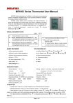
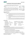
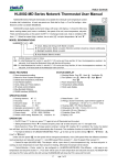
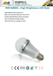
MR2008 Series Thermostat User Manual
MR2008 Series thermostats are available for individual room temperature control in
residential, industrial and business premises. Suitable for 2-pipe or 4-pipe Fan Coil configuration.
MR2008 adopts digital control technology with large LCD display, It shows the following items:
working states (cool, heat or ventilation), the speed of fan coil, room temperature, set-point. There
are following keys on the panel: On/Off “ ”, Exchange mode (cool, heat or ventilation) “ ”, timer
“�”, Select fan speed (high, medium, low or auto) “ ”, set-point temperature “�” and “�”.
MODEL DENOMINATIONS
T: Clock and timing on/off. Blank is invalid.
R: IR remote function. Blank is invalid. (remote controller should be ordered additionally)
L: Backlight available. Blank is invalid.
E: Auto Recovery. Blank is invalid.
BASIC FEATURES
� Room temperature setting
� Manual or Auto 3-speed changeover
� Defrost (low temperature protection)
� Auto Recovery ( E, Option )
� Clock and Timer ( -T, Option )
� IR remote control ( -R, Option )
� Blue Backlight ( -L, Option )
STATUS DISPLAY
� Working Status: Cool
, Heat
� Fan Speeds: Low
, Medium
Auto
� Room temperature display
� Temperature setting
� Clock week display ( -T, Option )
, Ventilation
, High
and
SPECIFICATIONS
� Sensing element:
NTC
� Accuracy :
±1℃
� Set-point range:
5℃ to 35℃
� Display range:
0~50℃
� Operating Temperature: 0~45℃
� Operating Humidity: 5~90%RH (non-condensing)
� Power supply:
AC 85~260V, 50/60Hz
� Switch current rating: Resistive: 2 A; Inductive: 1 A
� Rated Power: < 1 W
� Wirings: Screw-in terminals, each terminal capable of
accepting 2 x 1.5 mm2 or 1 x2.5 mm2 wires
� Housing: ABS+PC Flame Retardant
� Dimensions: 86 × 86 × 13 mm ( W × H × D )
� Hole pitch: 60mm ( Standard )
� Protection Class: IP30
� Display: LCD
OPERATION
� On/Off: Press “ ” to turn on, press “ ” again to turn off thermostat and its output.
� Setting temperature: Press “�” to reduce set-point, press “�” to raise set-point.
� Mode Selection: Press “ ” to change system working in cooling “ ”, heating “ ” or ventilation “ ” mode, the related icon
will flash, and it will be confirmed automatically after 5 seconds. The ventilation function is invalid for HR2008Y(E).
� Fan Speed Selection (HR2008DA[E]/DB[E]/DA2[E]/DB2[E]/FCV2[E]): Press “ ” to change fan speed among “
(Hi)”,
“ (Med)”, “ (Low)” or “ (Auto)”.
Under auto fan speed “ ”, the fan-speed will be changed automatically. Auto LOW-speed When the difference between
room-temperature and set-point exceed 1℃, Auto MED-speed When exceed 2℃, Auto HI-speed When exceed 3℃.
� Control Damper (HR2008Y[E]): The damper will be open when the room temperature is higher than set-point in cooling, or
room temperature is lower than set-point in heating, Otherwise the damper will be closed.
� Control Motorized Valve under 2-pipe configuration (HR2008DA[E]/DB[E]/DA2[E]/DB2[E]): If the difference between room
temperature and set-point exceed 1℃, FCU valve will be open; if room temperature and set-point are equal,
HR2008DA[E]/DA2[E] will close the FCU valve with the fan still running, HR2008DB[E]/DB2[E] will close the FCU valve and Fan
both.
� Control FCU Valve under 4-pipe configuration (HR2008FCV2[E]): In cooling, when the room temperature is higher than
set-point, the cooling valved will be opened. Otherwise it will be closed. Heating valve is always closed. In heating, When the room
temperature is lower than set-point, the heating valve will be opened. Otherwise it will be closed. Cooling valve is always closed.
AUTO RECOVERY ( Option )
� When the thermostat is at ON status for one minute, if power cut, it will return back to running automatically with the status
how it is one minute ago after power coming back.
� When the thermostat is at OFF status for one minute, if power cut, it will keep OFF status after power coming back.
FUNCTIONS ASSOCIATED WITH TIMER ARE IN THE FOLLOWING ( Option )
� Clock calibration: Press “ � ” till to display “hh:mm” and “mm” flash, press “�” or “�” to adjust minute, press “ � ”, “hh”
flash, press “�” or “�” to adjust hour; Press “�”, “week” flash, press “�” or “�” to adjust Mon to Sun.
� Sleep function setting: Press “�”, till to display “ ” and flash, press “�” to confirm, press “▼” to cancel.
� Timer on /Timer off: Press “�” till to display “�”and “TIMER ON” and all flash, and also “mm” flash, press “�” or “�” to
adjust minute, press “�”, “hh” flash, press “�” or “�” to adjust hour; Press “�” till to display “�” and “TIMER OFF” and all flash,
and also “mm” flash, press “�” or “�” to adjust minute, press “�”, “hh” flash, press “�” or “�” to adjust hour.
� Canceling timer on / Canceling timer off: Press “�” till to display “�” and “TIMER ON” and all flash, and also “mm” flash,
press “�” or “�” to adjust minute to “00”. press “�”, “hh” flash, press “�” or “�” to adjust hour to “00” ; Press “�” till to display
“�” and “TIMER OFF” and all flash, and also “mm” flash, press “�” or “�” to adjust minute to “00”. press “�”, “hh” flash, press
“�” or “�” to adjust hour to “00”.
DEFROST (LOW TEMPERATURE PROTECTION
PROTECTION))
� Description: when the thermostat turns off and the room temperature is lower than 5℃, it will be turned on automatically in
heating mode with “ ” showing, under HR2008DA[E]/DB[E]/DA2[E]/DB2[E]/FCV2[E] models, the system will be in heat mode
and fan runs in high speed. under HR2008Y[E] model, the motorized damper will be open. The thermostat will turn off when room
temperature is higher than 7℃.
� Set low temperature protection: Turn off the thermostat, press “ ” and hold for 3 seconds, it will display “00” or “01”, press
“�” or “� ” key to adjust. “00” indicates low temperature protection invalid, “01” indicates low temperature protection function
valid. The default is “00”.
WIRING DIAGRAMS
AC85~260V 50/60Hz
N L
L
Val
L
Valve
Low
VC
Med
VO
Fan
Damper
Hi
N
L
AC85~260V 50/60Hz
N L
AC85~260V 50/60Hz
N L
L
Val 2
Heating
VO
Val 1
Cooling
Low
Low
VC
Med
Valve
Med
Fan
Hi
Hi
N
N
Fan
MOUNTING
1. Open the main control
panel: put the screwdriver
(3.5mm) into the block
4mm along the bevel.
Prize up, open the clips.
2. Take off the wires.
3. As per wiring diagram,
connect it with terminals,
fixed by the screwdriver.
4. Put the connected
thermostat onto the back
panel in the wall, then fix it
with the two screws in the
packing box.
5. Put the cover with
degree angle, then fix
up two clips;
6. Push the places of
two down clips, fix
cover, and finish
installation.
30
the
the
the
the
Note: Be sure to connect all the wires as per the wiring diagrams and keep it away from water, mud and
other material so as to prevent the unit being spoiled!
Page 2 of 2