1
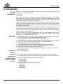
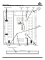
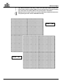
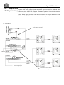
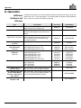
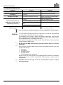
Series
User Manual
Edition Notes
Edition Notes
This User Manual covers the description, safety precautions, setup, installation,
operation, and maintenance for all Precision Video Panels offered by CHAUVET®. This
edition was published in March 2014.
Trademarks CHAUVET® is a registered trademark of CHAUVET & Sons Inc. (d/b/a CHAUVET® or
Chauvet). The CHAUVET® logo in its entirety including the Chauvet name and the
dotted triangle, and all other trademarks on this manual pertaining to services, products,
or marketing statements (example: It’s Green Thinking™) are owned or licensed by
CHAUVET®. Any other product names, logos, brands, company names, and other
trademarks featured or referred to within this document are the property of their
respective trademark holders.
Copyright Notice CHAUVET® owns the content of this user manual in its entirety, including but not limited
to pictures, logos, trademarks, and resources.
© Copyright 2014 CHAUVET®. All rights reserved.
Electronically published by CHAUVET® in the United States of America.
Manual Usage CHAUVET® authorizes its customers to download and print this manual for professional
information purposes only. CHAUVET® expressly prohibits the usage, copy, storage,
distribution, modification, or printing of this manual or its content for any other purpose
without its written consent.
Document Printing For best results, print this document in color, on letter size paper (8.5 x 11 inches),
double sided. If using A4 paper (210 x 297 mm), configure your printer to scale the
content accordingly.
Disclaimer CHAUVET® believes that the information contained in this manual is accurate in all
respects. However, CHAUVET® assumes no responsibility for any error or omissions in
this document. CHAUVET® reserves the right to revise this document and to make
changes from time to time in the content hereof without obligation of CHAUVET® to
notify any person or company of such revision or changes. This does not constitute in
any way a commitment by CHAUVET® to make such changes. CHAUVET® may issue
a revision of this manual or a new edition of it to incorporate such changes.
Document Revision The PVP™ Series User Manual, Rev. 3, supersedes all previous versions of this
manual. Please discard any older versions of this manual you may have, whether in
printed or electronic format, and replace them with this version.
Author
A. Leon
ii
Date
3/7/14
Editor
D. Couppe
Date
3/7/14
PVP™ Series User Manual, Rev. 3
Table of Contents
Table of Contents
1. Before You Begin ........................................................................................................................................ 1
What Is Included ................................................................................................................................................................ 1
Unpacking Instructions ...................................................................................................................................................... 1
Claims ............................................................................................................................................................................................ 1
Manual Conventions ...................................................................................................................................................................... 1
Symbols ......................................................................................................................................................................................... 1
Safety Notes ...................................................................................................................................................................... 2
Expected LED Lifespan ..................................................................................................................................................... 2
2. Introduction ................................................................................................................................................. 3
Product Description ........................................................................................................................................................... 3
Features ............................................................................................................................................................................ 3
Additional Products ........................................................................................................................................................................ 3
Optional Accessories ..................................................................................................................................................................... 3
Available Signal and Power Cables (optional) ............................................................................................................................... 3
Product Overview: PVP™ S5 and PVP™ S7 ................................................................................................................... 4
Product Dimensions .......................................................................................................................................................... 6
PVP™ Pixels Per Panel .................................................................................................................................................... 6
3. Setup ............................................................................................................................................................ 7
AC Power .......................................................................................................................................................................... 7
AC Plug .......................................................................................................................................................................................... 7
Power Linking................................................................................................................................................................................. 7
4. Mounting ...................................................................................................................................................... 8
Orientation ......................................................................................................................................................................... 8
Rig Kit (Sold Separately) ................................................................................................................................................... 8
Truss Installation ............................................................................................................................................................... 9
5. Joining Each PVP™ (Creating a Modular Design) .................................................................................... 10
Vertically Joining the Panels ............................................................................................................................................. 10
Important Notice ................................................................................................................................................................ 11
Horizontally Joining Panels ............................................................................................................................................... 12
6. Connecting (Cabling) Each PVP™ ............................................................................................................. 13
Testing Signal and Power Connections ............................................................................................................................ 13
Using the PVP™ Test button ............................................................................................................................................ 13
Connecting the Signal Input .............................................................................................................................................. 14
Connecting Power and Signal Cables ............................................................................................................................... 15
Connecting the Signal Between Joined Panels.............................................................................................................................. 15
Connecting the Power Between Joined Panels............................................................................................................................ 17
7. Typical PVP™ Installation .......................................................................................................................... 18
Step 1............................................................................................................................................................................................. 18
Step 2............................................................................................................................................................................................. 18
Step 3............................................................................................................................................................................................. 18
Step 4............................................................................................................................................................................................. 18
Step 5............................................................................................................................................................................................. 18
Step 6............................................................................................................................................................................................. 18
Step 7............................................................................................................................................................................................. 18
Step 8............................................................................................................................................................................................. 18
VIP™ Sample Video Wall System Setup .......................................................................................................................... 19
PVP™ Series User Manual, Rev. 3
-iii-
Table of Contents
8. Operation ..................................................................................................................................................... 20
Additional Hardware and Software .................................................................................................................................... 20
About CHAUVET® LED Studio ......................................................................................................................................... 21
Description ..................................................................................................................................................................................... 21
9. Technical Information ................................................................................................................................. 21
PVP™ Maintenance .......................................................................................................................................................... 21
Troubleshooting Guide ...................................................................................................................................................... 22
Returns .............................................................................................................................................................................. 22
10. Technical Specifications........................................................................................................................... 23
Contact Us ...................................................................................................................................................... 24
iv-
PVP™ Series User Manual, Rev. 3
Before You Begin
1. Before You Begin
What Is Included
Unpacking
Instructions
· 2 or 8 PVP™ (Precision Video Panels) models S5 or S7
· Neutrik® powerCON® Power input cable 6 ft (1.83 m)
o Included with 8-pack only
· Neutrik® etherCON® Signal Cables 2.46 ft (0.75 m)
o 2 or 8 cables based on the number of PVPs included
· Neutrik® powerCON® Power Cable 2.46 ft (0.75 m)
o 2 or 8 cables based on the number of PVPs included
· Flight Case (2 or 8-pack based on the number of PVPs included)
· Warranty Card
· User Manual
Immediately upon receiving this product, carefully unpack and check the container. Make
sure you have received all the parts indicated above in good condition.
Claims Upon receipt, if the container or the contents (the product and included accessories)
appear damaged from shipping, or show signs of mishandling, notify the carrier
immediately, not CHAUVET®. Failure to do so in a timely manner may invalidate your
claim with the carrier. In addition, keep the container and all the packing material for
inspection.
For other issues such as missing components or parts, damage not related to shipping,
or concealed damage, file a claim with CHAUVET® within 7 days of receiving the
merchandise.
Manual Conventions
Symbols
Convention
Meaning
1–512
50/60
<SET>
Settings
MENU>Settings
1–10
A range of values in the text
A set of mutually exclusive values in the text
A button on the product’s control panel
A product function or a menu option
A sequence of menu options
A range of menu values from which to choose in a menu
Yes/No
ON
A set of two mutually exclusive menu options in a menu
A unique value to be entered or selected in a menu
Symbols
Meaning
Critical installation, configuration, or operation information.
Failure to comply with this information may cause the product not
to work, damage third-party equipment, or cause harm to the
operator.
Important installation or configuration information. Failure to
comply with this information may keep the product from working.
Useful information.
PVP™ Series User Manual, Rev. 3
1
Before You Begin
Safety Notes
Please read the following Safety Notes carefully before starting to work with the product.
These notes provide important safety information about the installation, usage, and
maintenance.
This product contains no user-serviceable parts. Any reference to servicing in this
User Manual will only apply to properly trained CHAUVET® certified technicians.
Do not open the housing or attempt any repairs.
If product is being used in a mobile or touring application, the VIP™ Media System
must be mounted in a shock resistant (or shock mount) road case. This will help
prevent damage to the hard drives.
Please refer to all applicable local codes and regulations for the proper installation
of the product.
· Always connect the product to a grounded circuit to avoid the risk of electrocution.
· The product is rated IP50 and should only be used in environments meeting that
criteria.
· When hanging the product, always secure to a fastening device using a safety cable.
· The maximum ambient temperature is 122 °F (50 °C). Do not operate the product at
higher temperatures.
· Do not operate the product if you see damage on the housing, LED strips, or cables.
In any of these cases, have the damaged parts replaced by an authorized technician.
· Do not open or modify the product.
· Make sure the product is connected to the proper voltage provided in this manual’s
specifications and/or the specification sticker on the product.
· Never try to repair the product. Repairs carried out by unskilled people can lead to
damage or malfunction. Please contact CHAUVET® Technical Support.
Any damages caused by manual modifications are not subject to warranty.
CHAUVET® will not accept liability for any resulting damages caused by
unauthorized modifications or not observing the safety warnings and instructions
in the manual.
DO NOT mount this product outdoors! These panels do not allow wind to flow
through them and will act like a sail.
In the unlikely event that your CHAUVET® product may require service, contact
CHAUVET® Technical Support.
Expected LED
Lifespan
2-
LEDs gradually decline in brightness over time, mostly because of heat. Packaged in
clusters, LEDs exhibit higher operating temperatures than in ideal, single LED
conditions. For this reason, using clustered LEDs at their fullest intensity significantly
reduces the LEDs’ lifespan. The electrical, thermal management design of the PVP™
panel is designed to provide the longest LED lifespan possible. Under normal operating
conditions, this lifespan can be 50,000 hours or longer. If extending this lifespan is vital,
lower the operational temperature by improving ventilation around the fixture and
reducing the ambient temperature to an optimal operating range. In addition, limiting the
overall projection intensity may also help to extend the LEDs’ lifespan.
PVP™ Series User Manual, Rev. 3
Before You Begin
2. Introduction
Product
Description
The PVP™ is a Precision Video Panel. The PVP™ series is part of the VIP™ line of video
wall products and includes 2 models:
· PVP™ S5
· PVP™ S7
Each model is a video panel consisting of multiple SMD3528 tri-color LEDs. The number in
each model name indicates the pixel pitch (distance, in millimeters, between the LEDs) of that
model. When multiple panels are assembled and connected (signal and power), the entire
configuration becomes a modular video wall design.
The outer dimensions of each panel are identical. The difference between each model is the
vertical and horizontal spacing between the LEDs and the number of LED pixels. Both of
these values determine the total number of LED pixels provided on each panel. Each pixel is
one SMD3528 tri-color LED.
The aluminum alloy and stainless steel construction make the PVP™ reliable and solid, as
well as easy to install and dismantle. Multiple panels can be assembled horizontally or
vertically, and each model is interchangeable with the others. This flexibility provides
numerous modular design possibilities.
The PVP™ video wall system is addressed using a PC and CHAUVET® LED Studio
software. Refer to the CHAUVET® LED Studio User Manual for detailed information and
instructions on using CHAUVET® LED Studio.
Features
· 5.2 mm (PVP™ S5) or 7.8 mm (PVP™ S7) pixel pitch video panel system featuring superb
contrast through the use of blackface SMD3528 tri-color LEDs
· Tight binning of LEDs insures consistent color rendering across panels
· Easy installation and connectivity using Neutrik® powerCON® and etherCON® connectors
· Solid construction makes these a perfect product for long-term installation
· Interchangeable panels create large wall designs
· Tri-color SMD3528 LEDs provide better image quality and wider viewing angle
· Tight pixel pitch allows for equally effective close range and long-range viewing
· Designed for touring and permanent indoor installation
· Use with PVP™ Rigging Clamp or Rigging Bars and integrated, interlocking hardware for
fast and easy setup
Additional · VIP™ Driver (required)
Products
Optional · VIP™ Signal Distributor (required when using 25 PVP™s or more in your video wall)
Accessories · PVP™ Rigging Kit (required when vertically hanging panels from a truss or truss structure)
Available Signal · Signal cables (Neutrik® etherCON® Signal Extensions)
o MVPU-SIG5FT
and Power Cables
o MVPU-SIG10FT
(optional)
o MVPU-SIG25FT
· Power cables (Neutrik® powerCON® Extension)
o PCEXT5FT
o PCEXT10FT
o PCEXT25FT
o PCLEAD50FT
PVP™ Series User Manual, Rev. 3
3
Before You Begin
Product Overview: PVP™ S5 and PVP™ S7
Speego Male Connection
Service Access
Latch
Signal In/Out
Power In
Threaded
Mounting Hole
Size M10
(4x)
Power
Indicator LED
Signal LED
Test Button
Signal In/Out
Power Out
Speego Female connection
4-
PVP™ Series User Manual, Rev. 3
Before You Begin
The difference between each PVP™ model is the pixel pitch (space) between the
LEDs and the number of pixels (LEDs) in each row and column. The basic housing
and components are identical. Refer to the previous PVP™ illustration.
Warning: Service Access Latch is for use by CHAUVET® authorized technicians
only! Opening this will void the CHAUVET® warranty.
PVP™ S5
PVP™ S7
PVP™ Series User Manual, Rev. 3
5
Before You Begin
Product Dimensions
Each PVP™ model in the series has the same outside housing dimensions.
2.5 in
(63 mm)
19.7 in
(500 mm)
19.7 in
(500 mm)
PVP™ Pixels Per
Panel
Although each PVP™ has the same outer dimensions, the LED pixels per panel vary.
Each pixel is 1 SMD3528 tri-color LED. The following table provides the pixels per panel
in each PVP™. The model number (i.e., S5) indicates the pixel pitch in millimeters
between each light strip in that PVP™ model. For detailed specifications, refer to the
Technical Specifications table at the end of this User Manual.
Pixels per Panel
Total Pixels
PVP™ S5
PVP™ S7
96 x 96
9,216
64 X 64
4,096
You will use the number of pixels per panel and the screen resolution you would
like to use for your video wall display to calculate the number of panels,
horizontally and vertically, supported by a single VIP™ Driver. This Driver is
required to operate a CHAUVET® VIP™ video wall system. Diagrams of how the
PVP™ panels and the VIP™ Driver connect follow later in this manual. For detailed
information about the VIP™ Driver and panel calculation examples, refer to the
VIP™ Driver Quick Reference Guide.
6-
PVP™ Series User Manual, Rev. 3
Setup
3. Setup
AC Power
Each PVP™ has an auto-ranging power supply that works with an input voltage range of
100–240 VAC, 50/60 Hz. To determine the power requirements for each PVP™ in the
series, refer to the label affixed to the product. You can also refer to the Technical
Specifications chart in this manual.
The listed current rating indicates the maximum current draw during normal operation.
For more information, you may download Sizing Circuit Breakers from the CHAUVET®
website: www.chauvetpro.com.
Always connect this product to a protected circuit with an appropriate electrical
ground to avoid the risk of electrocution or fire.
Never connect this product to a rheostat (variable resistor) or dimmer circuit, even
if the rheostat or dimmer channel serves only as a 0 to 100% switch.
AC Plug Each PVP™ comes with a power linking cord to connect power between panels;
however, the power input cord is only included with the 8-pack flight case.
This cable has a powerCON® connector to connect to the PVP™ and an Edison plug for
power input. Use the table below as a reference to wire a new plug.
Connection
Wire (U.S.)
Wire (Europe)
Screw Color
AC Live
AC Neutral
AC Ground
Black
White
Green/Yellow
Brown
Blue
Green/Yellow
Yellow or Brass
Silver
Green
Power Linking All panels in the PVP™ Series support power linking. Refer to the following table for
specifications on each panel.
PVP™ S5
PVP™ S7
@ 120 V, 60 Hz
@ 208 V, 60 Hz
9
16
16
27
@ 230 V, 50 Hz
18
28
Please refer to all applicable local codes and regulations for the proper installation
of this product.
PVP™ Series User Manual, Rev. 3
7
Mounting
4. Mounting
Orientation
Each PVP™ is constructed of aluminum alloy and stainless steel. This ensures each
panel is stable and easy to install. Each panel also has a convenient built-in handle
located on the top, underside of the panel. This handle enables you to easily pick up and
securely hold each panel while mounting and working with the panels.
The PVPs can be assembled to provide any number of modular designs. The panels on
the top can be securely hung from a truss or other stable surface. Always hang in a safe
position with adequate space for ventilation, configuration, and maintenance.
CHAUVET® recommends following the general guidelines below.
· When selecting an installation location, consider ease of access for operation and
routine maintenance.
· Make sure to hang away from any flammable material, as indicated in the Safety
Notes section.
· Never mount in places where rain, extreme temperature changes, or restricted
ventilation may affect it.
· Make sure that the structure to which you are hanging the panels can support the
weight.
See the Technical Specifications for the weight requirement of each PVP™.
Rig Kit
(Sold Separately)
8-
PVP™ Series User Manual, Rev. 3
Setup
Truss Installation
Refer to the following diagram for truss installation. CHAUVET® offers the PVP™ Rig Kit
(sold separately) specifically designed for hanging the panels.
Rig Kit
(sold separately)
PVP™ Series User Manual, Rev. 3
9
Joining Each PVP™ (Creating a Modular Design)
5. Joining Each PVP™ (Creating a Modular Design)
PVPs are joined together to create a modular designed video wall. Because the panels
are interchangeable, you can create a video wall by joining several of the same model or
joining different models to create a larger or more complex video wall.
Vertically Joining
the Panels
Each PVP™ can be easily joined vertically to a truss using 2 Rig Kits (sold separately)
and the 2 female speego connections located at the top corner of each panel. Use the
male speego connections at the bottom of each panel to connect additional panels.
These connectors stay recessed when not being used.
Speego
Clamps must be installed as shown above on a single column installation.
10-
PVP™ Series User Manual, Rev. 3
Joining Each PVP™ (Creating a Modular Design)
Use the following instructions to join panels vertically:
1. Line up the male and female speegos at the top and bottom of each panel.
2. Push male speego connections into female speego connections.
3. Turn the top knob ¼ turn to hold in place.
4. Align panels and twist bottom screw collar clockwise to secure panel in place.
Once the panels are fastened, make sure to twist the bottom collar clockwise to
lock the panels in place.
For PVP™ panels manufactured prior to 2014, the speego is designed to be handtightened only. Using tools may damage the speego and void the panel warranty.
See Important Notice.
Turn ¼ turn to hold panel in place
Twist tight to secure panel
Important Notice
PVP™ Series User Manual, Rev. 3
CHAUVET® Professional has redesigned the speego connectors for all PVP
panels starting in 2014. When assembling the PVP panels with these new speego
connectors, you are able to use a crescent wrench to achieve proper alignment.
Please use caution when using a wrench and only rotate it between a 1/4 and 1
complete clockwise rotation. Do not over-tighten the speego; doing so may cause
damage to the video panel.
11
Joining Each PVP™ (Creating a Modular Design)
Horizontally Joining
Panels
Each PVP™ can be easily joined horizontally using the 2 horizontal locking knobs on the
inside, left-hand top and bottom of each panel.
Clamps may be installed as shown below when 2 or more columns are installed.
Use the following instructions to join panels horizontally:
1. Line up the male and female speegos at the top and bottom of each panel.
2. Push male speego connections into female speego connections.
3. Turn the top knob ¼ turn to hold in place.
4. Align panels and twist bottom screw collar clockwise to secure panel in place. In
order to achieve better alignment, it may be necessary to slightly loosen the speego.
Once the panels are fastened, make sure to twist the bottom collar clockwise to
lock the panels in place.
Turn ¼ turn to hold panel in place
Twist tight to secure panel
12-
PVP™ Series User Manual, Rev. 3
Connecting (Cabling) Each PVP™
6. Connecting (Cabling) Each PVP™
Testing Signal and
Power Connections
Each PVP™ has 2 power sockets and 2 signal sockets.
· The Power IN and Signal sockets are located on the upper right-hand corner of each
panel.
· The Power OUT and Signal sockets are located on the lower right-hand corner of
each panel.
· The Signal sockets may be used interchangeably.
· Each PVP™ has LED indicator lights.
· Each panel indicates a successful power connection when the Power indicator light
remains red.
· Each panel indicates video signal reception when the Signal LED indicator light blinks
green. This light should be blinking to indicate good reception.
Rear Panel View
Underside of Rear View
Signal LED indicator
Power In
Power LED indicator
Test Button
Power Out
Signal LED indicator
Signal Connection
Using the PVP™
Test button
Each PVP™ also has a Test button, used to ensure all LEDs are functional. Use the
Test button on each panel to perform a self-test. If self-testing, you must perform the test
individually for each PVP™. You do not need to connect to a signal or use software.
When using the Test button, make sure the PVP™ is not connected to the VIP™
Driver.
To use the Test button, you must connect the power, but do not connect the signal
cables. Press the Test button to toggle through various LED light display configurations.
PVP™ Series User Manual, Rev. 3
13
Connecting (Cabling) Each PVP™
Connecting the
Signal Input
The VIP™ video wall system uses 2 basic setup configurations to connect the signal to
the video wall:
1. A configuration using 24 or less panels.
2. A configuration using more than 24 panels.
The next section, Connecting Power and Signal Cables, gives information on connecting
power and signal between joined panels and to the rest of the VIP™ system.
The following configuration of 24 panels shows a direct connection from the signal to the
VIP™ Driver into the first panel’s Signal Input socket. Refer to the VIP™ Driver Quick
Reference Guide for information and instructions on the VIP™ Driver.
Single PVP™
(panel)
Backup
connection from
the last PVP™ in
the series
DVI-D
VIP™ Driver
Signal Socket
The VIP™ system’s maximum signal load is 24 or less panels on a single signal
cable connection. When using more than 24 panels in a video wall design, you will
need a VIP™ Signal Distributor and additional signal cables to accommodate the
number of panels over 24. A VIP™ Signal Distributor output supports up to 8
signal output lines, providing up to 192 total panels that can be connected from
the VIP™ Signal Distributor. You also can add more VIP™ Signal Distributors to a
VIP™ video wall system. Refer to the VIP™ Signal Distributor Quick Reference
Guide for more information.
Pixel limitation may limit to less than 192 panels.
14-
PVP™ Series User Manual, Rev. 3
Connecting (Cabling) Each PVP™
Connecting Power
and Signal Cables
The following sections provide information and diagrams on connecting signal and power
between panels.
Refer to the Introduction or Operation sections in this User Manual for available cables
and item numbers.
Connecting Signal cable panel connections can use several different configurations. The basic
the Signal Between configuration to connect the signal from one panel to the next is as follows.
Joined Panels · The source signal is connected to the first panel.
· A signal cable is then connected from the first panel.
· The connections continue to daisy-chain until all panels are connected.
· The route of the cables used to make the signal connections can vary.
The following diagrams are recommended suggestions for signal connections between
24 or less panels, and more than 24 panels.
Refer to Connecting Signal Input for information and instructions on connecting the
signal from the source.
This diagram shows an example of a simple signal connection using 24 or less PVP™s.
Signal Jumper Cable
DVI-D
VIP™ Driver
Video Signal Cable
in from VIP™ Driver
max. cable length
100 m/328 ft
PVP™ Series User Manual, Rev. 3
May be used to run
a backup line to the
VIP™ Driver
15
Connecting (Cabling) Each PVP™
The following diagram shows an example of a signal connection configuration using
more than 24 panels. A video wall design with more than 24 panels requires:
· Incoming signal connection to the VIP™ Driver.
· VIP™ Driver connection to the VIP™ Signal Distributor.
· Signal cable connections as determined by the number of panels in the video wall
design and the desired layout, for ease of setup.
Every group of 24 panels will require another signal cable from the VIP™ Signal
Distributor. Eight signal cables can be connected to a single VIP™ Signal
Distributor.
DVI-D
Up to 24 Panels
VIP™ Driver
etherCON®
Up to 24 Panels
etherCON®
VIP™ Signal
Distributor
Signal Jumper Cable
In this configuration, the backup from the driver may be connected to the last
panel in any group of panels, or to any free connection to the VIP™ Signal
Distributor, including input “B.”
16-
PVP™ Series User Manual, Rev. 3
Connecting (Cabling) Each PVP™
Connecting Power cable panel connections can also use different configurations. The basic
the Power Between configuration to connect the main power supply from one panel to the next is:
Joined Panels · The main power is connected to the first panel’s Power Input or Output.
· A powerCON® cable is then connected to the first panel’s Power Output and
connected to the next panel’s Power Input.
· The connections continue until all panels are connected.
The power input cord for the main is included when purchasing an 8-pack flight
case ONLY. CHAUVET® recommends the Neutrik® powerCON® extension cable,
item number PCLEAD50FT, available from CHAUVET®, if additional cables are
requried.
Connect power between the panels using the same procedure as the signal only using
the Power Input and Power Output connectors. You must adhere to the power-linking
specifications for each PVP™ model.
Refer to the Power Linking section for details on the number of panels that can be linked
based on voltage from a single power connection.
Power linking more panels than recommended will void your warranty and
increase the risk electrocution or fire!
Refer to the following diagram for an example of power connection from the main and to
each connected panel.
This example is using an PVP™ S5 or S7, power linking 7 panels horizontally @ 120 V.
MAIN POWER IN
MAIN POWER IN
MAIN POWER IN
PVP™ Series User Manual, Rev. 3
17
Typical PVP™ Installation
7. Typical PVP™ Installation
Because a video wall system can include different components to provide a simple to complex modular wall design, use
the following steps as a general guide to get started.
Step 1 Open and examine the PVP™ flight case to make sure you have received all products and
accessories and that each one is in good condition.
Step 2 Apply power and run the self-test for each PVP™ to ensure all LEDs and inside connections
in each panel are working (optional).
Step 3 Create a stable mounting surface (i.e., truss or other stable surface) for PVP™ mounting.
Step 4 Mount the first top row of the PVP™s. Refer to the Mounting section in this User Manual.
Step 5 Adjust the alignment of the first row using the speego connectors.
Step 6 Connect the signal source to the VIP™ Driver. Connect the VIP™ Driver to the VIP™ Signal
Distributor (if applicable).
Step 7 Connect either VIP™ Driver or VIP™ Signal Distributor (if being used) to the Input Signal
socket of the first panel in your connection chain.
Step 8 Based on your video wall configuration (design), join each panel, either horizontally or
vertically, using the instructions in the section, Joining Each PVP™ (Creating a Modular
Design).
Refer to the instructions and information in the section of this User Manual, Connecting
(Cabling) Each PVP™.
18-
PVP™ Series User Manual, Rev. 3
Typical PVP™ Installation
VIP™ Sample Video
Wall System Setup
The following diagram provides a sample setup for a CHAUVET® VIP™ video wall
system. This system setup includes an optional signal processor for additional video
sources, and the VIP™ Signal Distributor to support more than 24 panels. Note that the
two-driver setup shown here allows for simultaneous playback of pre-recorded and live
content, all directed from a single PC.
Refer to the signal processor User Manual and the VIP™ Signal Distributor Quick
Reference Guide for information on those video wall components.
For pre-recorded content; no video processor
in line with this connection
You May Connect up to 4 VIP™
Drivers in a single system
Second driver allows for external
video sources for live playback
PVP™ Series User Manual, Rev. 3
19
Operation
8. Operation
Additional
Hardware and
Software
Item
In addition to the panels, you will need other hardware and software to design, build, and
operate your VIP™ video wall system. The following table summarizes these additional
items—some are required and others are optional.
Description
VIP™ Driver
Interface between the signal source, LED
Studio, and the PVP™ being used
LED Studio
Software application used to design and run
the PVPs comprising the video wall. A PC is
needed
Connects between the VIP™ Driver and the
PVPs to distribute the source signal from the
VIP™ Driver to the video wall when using
more than 24 panels
Provides hardware needed to mount PVPs.
VIP™ Signal Distributor
(optional up to 24 panels)
PVP™ Rigging Kit
(optional)
Neutrik® etherCON®
Signal Extension
(optional)
Neutrik® powerCON®
Extension
(optional)
etherCON® Signal Extension, 18 in
etherCON® Signal Extension, 5 ft
etherCON® Signal Extension, 10 ft
powerCON® Extension, 18 in
powerCON® Extension, 5 ft
powerCON® Extension, 10 ft
powerCON® Extension, 25 ft
powerCON® Extension, 50 ft
powerCON® Bare Wire Lead, 50 ft
PVP™ 2-pack and 8-pack PVP™ S5 2-Pack
PVP™ S5 8-Pack
PVP™ S7 2-Pack
PVP™ S7 8-Pack
VIP™ Media System and Rack mountable, video computer system with
one VIP™ Driver
the PVP™ Driver and LED Studio software
VIP™ Media System with Rack mountable, video computer system with
ArKaos Media Master
the PVP™ Driver and LED Studio software, as
Express + KN and One well as ArKaos Media Master Express
VIP™ Driver
ArKaos Media Master
Video playback software + KN control
Express + KN
20-
Item Code
Item Number
99090575
VIPDRIVER
99090576
VIPSIGDISTRO
20090598
PVP-RK
19090363
19090364
19090365
19110372
19110373
19110374
19110375
19110376
19110377
20090579
20090571
20090580
20090572
MVPU-SIG18IN
MVPU-SIG5FT
MVPU-SIG10FT
PCEXT18IN
PCEXT5FT
PCEXT10FT
PCEXT25FT
PCEXT50FT
PCLEAD50FT
PVPS5x2
PVPS5X8
PVPS7x2
PVPS7X8
MVPU-MS
MVPU-MSMME
MVPU-MSPRO
PVP™ Series User Manual, Rev. 3
Operation
About CHAUVET®
LED Studio
CHAUVET® LED Studio is a powerful and easy-to-learn software application used to
design and run the VIP™ video wall system. The following is some introductory
information about this software.
Refer to the CHAUVET® LED Studio User Manual for detailed information and
instructions on setting up and using CHAUVET® LED Studio with your CHAUVET®
VIP™ video wall system.
Description CHAUVET® LED Studio enables you to create and control your video wall by
addressing the panels included in your video wall including pixel pitch and layout.
Once you have physically created your modular video wall design by joining the panels,
connecting power, signals, and the VIP™ Media System, you recreate that design within
LED Studio.
Detailed information and instructions are in the CHAUVET® LED Studio User Manual.
CHAUVET® does not recommend using CHAUVET® LED Studio for live show
playback. For this purpose, CHAUVET® offers Arkaos MediaMaster, which offers
numerous playback triggers, including DMX, Art-Net, MA-net, MIDI, and QWERTY.
9. Technical Information
PVP™ Maintenance
To maintain optimum performance and minimize wear, the user should clean this
product regularly. Usage and environment are contributing factors in determining the
cleaning frequency.
As a rule, clean this product at least twice a month. Dust build-up reduces light output
performance and can cause overheating. This can lead to reduced light source life and
increased mechanical wear.
To clean a PVP™, follow the recommendations below:
· Unplug the panel from power.
· Wait until the unit at room temperature.
· Use a soft brush to remove dust collected on the external components.
· Wipe the outside of the LED strips with a soft, lint-free cloth dampened with a solution
of water and detergent. Apply gentle pressure only.
· Make sure all connections are thoroughly dry before reconnecting power and signal
cables.
Always dry the external surfaces carefully after cleaning them.
PVP™ Series User Manual, Rev. 3
21
Technical Information
Troubleshooting Guide
Symptom
Cause(s)
All LEDs are blinking
LEDs on a specific circuit are not
lit/working
All LEDs do not light
PVP™ does not power up
(LED power indicator does not
light during “self-test”)
PVP™ displays no images or
spotted images
Contact failure
Power input cable may be connected
incorrectly
Input cables connected incorrectly
No power
Loose or damaged power cord
Faulty power connection inside the
PVP™
Faulty external power supply
Action(s)
Fix the loose LEDs or try re-plugging
Remove and connect correctly
Find the incorrectly connected cables
and reconnect properly
Check for voltage on outlet
Check power cord
Send for repair
Disconnect and reconnect the signal
cable, or replace the cable
If you still experience technical problems, contact CHAUVET® Technical Support.
Returns
You must send the product prepaid, in the original box, and with the original packing
and accessories. CHAUVET® will not issue call tags.
Call CHAUVET® and request a Return Merchandise Authorization (RMA) number
before shipping the product. Be prepared to provide the model number, serial number,
and a brief description of the cause(s) for the return.
Clearly label the package with an RMA number. CHAUVET® will refuse any product
returned without an RMA number.
DO NOT write the RMA number directly on the box. Instead, write it on a properly
affixed label.
Once you have received the RMA number, include the following information on a piece
of paper inside the box:
· Your name
· Your address
· Your phone number
· The RMA number
· A brief description of the problem(s)
Be sure to pack the product properly. Any shipping damage resulting from inadequate
packaging will be the customer’s responsibility. FedEx packing or double-boxing is
recommended.
CHAUVET® reserves the right to use its own discretion to repair or replace
returned product(s).
22-
PVP™ Series User Manual, Rev. 3
Technical Specifications
10. Technical Specifications
Light Source
Pixels per Panel
Pixel Pitch (between LEDs)
Pixel Density
Display Refresh Rate
Video Refresh Rate
Viewing Angle
PVP™ S5
PVP™ S7
Tri-color SMD3528 LED
Tri-color SMD3528 LED
96 x 96 (9,216 total)
64 x 64 (4,096 total)
5.2 mm
7.8 mm
36,864/m
2
16,384/m
2
1,200 Hz (flicker-free)
1,200 Hz (flicker-free)
60 Hz
60 Hz
°
°
140
140
1,500 NIT
1,500 NIT
6500–9500 K
6500–9500 K
Red
620–625 nm
620–625 nm
Green
520–525 nm
520–525 nm
Blue
465–470 nm
465–470 nm
Power Supply Type
Switching
Switching
AC Voltage Range
100–240 VAC, 50/60 Hz
100–240 VAC, 50/60 Hz
Voltage Selection
Auto-ranging
Auto-ranging
Power Consumption 120 V, 60 Hz
126 W; 1.05 A
102 W; 0.85 A
Power Consumption 208 V, 60 Hz
128 W; 0.62 A
105 W; 0.50 A
Power Consumption 230 V, 50 Hz
129 W; 0.56 A
106 W; 0.47 A
Power Linking @ 120 V, 60 Hz
9 units
16 units
Power Linking @ 208 V, 60 Hz
16 units
27 units
Power Linking @ 230 V, 50 Hz
18 units
28 units
19.7 x 19.7 x 2.5 in
(500 x 500 x 63 mm)
19.7 x 19.7 x 2.5 in
(500 x 500 x 63 mm)
16.3 lb (7.39 kg)
15.8 lb (7.17 kg)
N/A
N/A
Mounting Design
Modular
(horizontal and vertical)
Modular
(horizontal and vertical)
Housing Material
Aluminum alloy
Aluminum alloy
Power Connection
Neutrik® powerCON®
Neutrik® powerCON®
Control Connection
Neutrik® etherCON®
Neutrik® etherCON®
Luminance
Color Temperature
Color Wavelengths:
Dimensions
Weight
Transparency
PVP™ Series User Manual, Rev. 3
-23-
Contact
Us
WORLD HEADQUARTERS - CHAUVET®
General Information
th
Address:5200 NW 108 Avenue
Sunrise, FL 33351
Voice: (954) 577-4455
Fax:
(954) 929-5560
Toll free: (800) 762-1084
Technical Support
Voice: (954) 577-4455 (Press 4)
Fax:
(954) 756-8015
Email: [email protected]
World Wide Web
www.chauvetlighting.com
UNITED KINGDOM AND IRELAND - CHAUVET® Europe Ltd.
General Information
Address:Unit 1C
Brookhill Road Industrial Estate
Pinxton, Nottingham, UK
NG16 6NT
Voice: +44 (0)1773 511115
Fax:
+44 (0)1773 511110
Technical Support
Email: [email protected]
World Wide Web
www.chauvetlighting.co.uk
MEXICO - CHAUVET® Mexico
General Information
Address:Av. Santa Ana 30
Parque Industrial Lerma
Lerma, Mexico C.P. 52000
Voice: +52 (728) 285-5000
Technical Support
Email: [email protected]
World Wide Web
www.chauvet.com.mx
Outside the U.S., United Kingdom, Ireland, or Mexico, contact your dealer. Follow their instructions to
request support or to return a product. Visit our website for contact details.