1
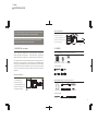
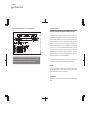
2 colors
PANTONE BLACK M
PANTONE 400 M
USER MANUAL
MODULE 16 SMD RGB (1PXL)
BOARD 16 SMD RGB (1PXL)
Please check for the latest updates and changes on the TRAXON website.
©TRAXON TECHNOLOGIES ALL RIGHTS RESERVED.
WWW.TRAXONTECHNOLOGIES.COM
HONG KONG
NEW YORK
PARIS
TOKYO
RIO DE JANEIRO
FRANKFURT
MELBOURNE
SHANGHAI
BIRMINGHAM
ROTTERDAM
Smart Chip - Version 1.2 Manual - Version 1.0
USER MANUAL & WARRANTY
1. INTRODUCTION: P1
2. CONTENTS: P2
3. SAFETY AND OPERATION: P3
4. PRODUCT DESCRIPTION: P4
5. INSTALLATION AND SYSTEM CONFIGRATION: P4-18
5-1 MOUNTING: P4-7
5-2 DATA CONNECTION: P8-11
5-3 POWER CONNECTION: P12-17
5-4 CONTROL: P18
6. CARE AND MAINTENANCE: P19
7. TECHNICAL SPECIFICATION: P19-20
8. WARRANTY STATEMENT: P20
1 colors
PANTONE BLACK M
FOR YOUR OWN SAFETY AND THAT OF THE PRODUCT, PLEASE READ THIS USER
GUIDE CAREFULLY BEFORE BEGINNING SET-UP AND INSTALLATION!
BOARD 16 SMD RGB (1PXL)
• 16 Ultra Bright SMD LED
• DMX or RF Control Options
• Auto-Addressing (DMX Version Only)
CAUTION: FOR BOARD, DO NOT OPEN OR HANDLE EXCEPT AT A STATIC FREE
• SMART CHIP™ (DMX Version Only)
WORKSTATION OR WEARING ANTISTATIC WRIST STRAP.
• RJ45 Cat5 Data Cabling
1. INTRODUCTION
2. CONTENTS
(1PXL SERIES)
MODULE 16 SMD RGB (1PXL / DMX) MO-BO-52101
BOARD 16 SMD RGB (1PXL / DMX) MO-BO-50001
MODULE 16 SMD RGB (1PXL / RF) MO-BO-22101
BOARD 16 SMD RGB (1PXL / RF) MO-BO-20001
MODULE 16 SMD RGB (1PXL / SLAVE) MO-BO-02101
BOARD 16 SMD RGB (1PXL / SLAVE) MO-BO-00101
MODULE 16 SMD RGB (MO-BO-52101, MO-BO-22101, MO-BO-02101)
4 X Screw Caps
These products are part of the Traxon™ Modules product line, enabling the use of an
RGB LED color changing systems in a matrix configuration. On-board SMART CHIP™
technology (used in the DMX versions) with the powerful feature of Auto-Addressing
enables fast and easy setup and installation. High power LED technology combined
with low power consumption brings the best solution possible for any number of
applications.
DC Starter Cable
Power Extension Cable
MODULE 16 SMD RGB (1PXL)
Data Starter Cable
Data Extension Cable
1 x Module 16 SMD RGB
(Data & Power cables fitted)
2 x Quick Clip
Mounting Kits
4 X M4 Mounting Screws
OPTIONAL ACCESSORIES
• LED Module with Housing
• 16 Ultra Bright SMD LED
BOARD 16 RGB SMD (MO-BO-50001, MO-BO-20001, MO-BO-00101)
• DMX or RF Control Options
• Auto-Addressing (DMX Version Only)
1 X RJ45 Data Cable
4 x Mounting Spacers
• SMART CHIP™ (DMX Version Only)
• Quick Clip Installation System
1 x Board 16 SMD RGB
1 X Power Interconnection Cable
4 X M4 Mounting Screws
OPTIONAL ACCESSORIES
DC Starter Cable
1
RJ45 Data Cable
Power Interconnection Cable
2
1 colors
PANTONE BLACK M
3. SAFETY AND OPERATION
CAUTION – UNPLUG THE POWER SUPPLY FROM THE MAINS POWER BEFORE
CONNECTING ANY CABLES AS THIS CAN DAMAGE THE PRODUCTS !
CAUTION – AVOID LOOKING DIRECTLY INTO THE LED LIGHT SOURCE AT CLOSE
4. PRODUCT DESCRIPTION
The ‘Module 16 SMD RGB’ and ‘Board 16 SMD RGB’ are part of the MODULES product
line and features include low power consumption, high light output with a wide even beam
angle and an option of DMX 512 with SMART CHIP™ technology or RF Remote control.
The SMART CHIP™ is a world first technology that includes the powerful feature of
automatic DMX start addressing and channel mode selection.
RANGE FOR YOUR OWN SAFETY.
• MASTER–MASTER (DMX Versions)
ANY PERSONS INSTALLING THIS PRODUCT SHOULD COMPLY WITH LOCAL
‘Module 16 SMD RGB DMX’ and ‘Board 16 SMD RGB DMX’ are referred to as MASTER fixtures with
control via DMX512 with SMART CHIP™ technology. Once the primary MASTER has been selected,
STANDARDS AND REGULATIONS AND MUST BE QUALIFIED FOR THE HANDLING
subsequent MASTER models can be added with individual control via DMX. The on-board SMART
OF ELECTRICAL EQUIPMENT.
CHIP™ automatically assigns DMX start addresses to all connected MASTER fixtures upon powering
up of the system.
This product is designed for indoor use only.
An ambient operating air temperature range of 0°C~+50°C (+32°F ~ +122°F) must be
adhered to at all times.
If the fixture has been subjected to drastic temperature variances e.g. following transportation,
do not connect the fixture until it has reached room temperature, as internal condensation
buildup may damage the fixtures’ electronics.
When installing the fixtures and system power supplies in the chosen locations, please ensure
that they will not be exposed to moisture, extreme heat or direct sunlight and that it is in a dirt
and dust free environment keeping the fixtures and system power supplies within their
operating boundaries.
Please study all functions in this User Manual thoroughly and check the latest Technical
Specifications Sheets available from our website [www.traxontechnologies.com] before
set-up.
• MASTER–SLAVE (DMX & RF Remote Versions)
‘Module 16 SMD RGB DMX,’ ‘Module 16 SMD RGB RF’ and ‘Board 16 SMD RGB DMX,’ ‘Board SMD
RGB RF’ are all referred to as being MASTER fixtures with control via DMX512 with SMART CHIP™
technology or via RF Remote depending on the model chosen. Using them together with either of the
SLAVE versions ‘Module 16 SMD RGB SLAVE’ or ‘Board 16 SMD RGB SLAVE,’ the MASTER-SLAVE
control relationship is utilized for simultaneous color change of all fixtures, with only the MASTER
receiving the control signal and then sending the same signal to the other fixtures in the daisy-chain.
5. INSTALLATION AND SYSTEM CONFIGURATION
5-1 MOUNTING
5-1.1 MODULE 16 SMD RGB
The Module 16 SMD RGB can be installed in different ways: permanent fitting by front mounting
using M4 screws - with or without Quick Clip Mounting brackets as mounting aid – or for temporary
fittings, using only the Quick Clip mounting kit.
3
4
1 colors
PANTONE BLACK M
For front mounting with M4 screws: Position the Module 16 SMD RGB in the desired location
FIG 2
and fasten the mounting screws from the front, taking care not to over tighten as this may
damage the housing. Once all screws have been fixed in place, use the screw caps provided to
cover the screw holes. (FIG1)
For multi module installation, the provided Quick Clip Mounting kit can be used as mounting aid.
Affix the mounting brackets to the rear side of the Module 16 SMD RGB fixtures before
mounting: for the outer most Modules, snap the mounting clips into two; corner Modules do not
require any Quick Clip mounting bracket. Once all Modules have thus been hooked together,
align them on the desired surface and fasten the mounting screws from the front. (FIG1)
FIG 1
5-1.2 BOARD 16 SMD RGB
To mount the Board 16 SMD RGB, first fit the nylon spacers into the mounting holes from the
rear of the board. Then use the M4 screws to fasten the board to a flat surface taking care not to
fit too tightly, but enough to hold it firmly in place (FIG 3).
FIG 3
Note: Should the installation setup exceed 1sqm, it is recommended to mount the Module 16
SMD RGB in segments of 4x4 modules.
For temporary installation, the Module 16 SMD RGB can be fixed to the Quick Clip mounting
clips without screwing, allowing for easy mounting and removal of the fixtures. First, select the
Quick Clip mounting brackets for Center- and Edge-Modules and fix them to any flat surface by
the center holes using the provided M4 screws. Please refer to the measurements specified for
5
Center-to-Center Module and Center-to-Edge Modules in FIG 2.
6
1 colors
PANTONE BLACK M
WHEN USING THESE PRODUCTS FOR ANY APPLICATION, THOUGHT AND
CONSIDERATION ALWAYS NEED TO BE TAKEN INTO ACCOUNT FOR PRODUCT
VENTILATION AND POSSIBLY COOL AIR FLOW WHERE THEY ARE INSTALLED,
ESPECIALLY WHEN THE PRODUCTS ARE BEING USED IN SEALED AREAS SUCH
5-2 DATA CONNECTION
5-2.1 MODULE 16 SMD RGB ( ALL VERSIONS )
Data connection is via the 8-PIN fly leads fitted to the Module. The cable length is designed to
connect Modules in a vertical configuration. For connection as per the diagram (FIG 5), please follow
AS WALLS, FLOORS OR ANY ENCLOSED AREA WHERE HEAT CAN BUILD UP TO
the DATA IN and DATA OUT markings on the back of the Module when installing and firmly connect
VERY HIGH TEMPERATUES VERY QUICKLY. THESE PRODUCTS MUST BE KEPT
the cables together in a daisy-chain configuration.
WITHIN THE SET OPERATING TEMPERATURE BOUNDARIES AS PER THE
FIG 5
PRODUCT SPECIFICATIONS AT ALL TIMES - FAILING TO FOLLOW THESE
RECOMMENDATIONS WILL RESULT IN POSSIBLE DAMAGE TO THE PRODUCTS
AND VOID THE PRODUCT WARRANTY. ALL RESPONSIBILITY WILL STAND WITH
BACK
THE PRODUCT USER TO FULFILL THESE REQUIREMENTS.
*
RF
PLEASE CHECK THE PIN ASSIGNMENT FOR THE CONNECTION OF DIFFERENT
PRODUCTS AND MAKE SURE THEY ARE PIN TO PIN COMPATIBLE, OTHERWISE
IT MIGHT DAMAGE THE PRODUCT.
7
8
1 colors
PANTONE BLACK M
IMPORTANT NOTE - DATA CONNECTION
• MASTER–MASTER DMX DATA CONNECTION
PLEASE NOTE THAT OPTIONAL EXTENSION CABLES ARE REQUIRED WHEN
CONNECTING THE MODULE IN A CONFIGURATION OTHER THAN VERTICAL.
For MASTER-MASTER DMX data connections, a maximum of 170 MASTER Boards can be
connected together in a daisy-chain configuration. The on-board SMART CHIP™ technology is used
for automatic DMX start address setting once all data connections are made and the system power
• MASTER–MASTER DMX DATA CONNECTION
For MASTER-MASTER DMX data connection, a maximum of 170 MASTER fixtures can be
connected together in a daisy-chain configuration. The on-board SMART CHIP™ technology is used
to automatically assign the DMX start-addresses once all data connections are made and when
powering up the system power supplies. (DMX versions.)
Please see below the detailed pin-out configuration (FIG 6).
supply is switched on (FIG 7).
• MASTER–SLAVE DATA CONNECTION
For MASTER-SLAVE data connection a maximum of 99 SLAVE Boards can be connected to 1
MASTER Board in a daisy-chain configuration (FIG 7).
FIG 7
DMX 512 CONTROLLER
NOTE:
BUTLER - LM-CS-50041
FIG 6
EACH BUTLER CAN CONNECT
MAX 340PCS BOARD MASTER
(2 X 170PCS).
DMX SIGNAL IN
DATA CABLE - SP-DA-001XX
MAX 170 MODULES, 100M SPAN
OUT
MASTER SLAVE SIGNAL
OUT
IN
OUT
MASTER SLAVE SIGNAL
MAX 100 MODULES, 100M SPAN
MASTER SLAVE SIGNAL
O UT
IN
OUT
ADDITIONAL SLAVE
AS REQUIRED
MASTER
IN
ADDITIONAL SLAVE
AS REQUIRED
MASTER
ADDITIONAL SLAVE
AS REQUIRED
CAUTION - PLEASE ENSURE THAT THE POWER IS SWITCHED OFF WHEN THE
DATA CABLES ARE BEING CONNECTED
MASTER
ADDITIONAL SLAVE
AS REQUIRED
MASTER fixture in a daisy-chain configuration.
IN
MASTER SLAVE SIGNAL
• MASTER–SLAVE DATA CONNECTION
For MASTER-SLAVE data connection a maximum of 99 SLAVE fixtures can be connected to 1
DMX SIGNAL
OUT
OUT
DMX SIGNAL
IN
ADDITIONAL
MASTER AS
REQUIRED
OUT
DMX SIGNAL
SLAVE
ADDITIONAL SLAVE
AS REQUIRED
ADDITIONAL SLAVE
AS REQUIRED
5-2.2 BOARD 16 SMD RGB ( ALL VERSIONS )
Data connection is via the RJ-45 sockets on the Boards and the RJ-45 CAT5 patch cables that are
ADDITIONAL SLAVE
AS REQUIRED
supplied with each Board for installation. For connection as per the diagram below, please follow the
DATA IN and DATA OUT markings on the rear of the Boards and firmly connect the cables in a
9
daisy-chain configuration.
DATA CABLE CONNECTION
SLAVE
10
1 colors
PANTONE BLACK M
• RJ 45 INTERCONNECTION CABLE - PIN OUT CONFIGURATION
FIG 8
5-3 POWER CONNECTION
PLEASE READ THE FOLLOWING DIRECTIONS PRIOR TO CONNECTING WITH CARE:
WHEN USING THESE PRODUCTS FOR ANY APPLICATION, THOUGHT AND
CONSIDERATION ALWAYS NEED TO BE TAKEN INTO ACCOUNT FOR PRODUCT
VENTILATION AND POSSIBLY COOL AIR FLOW WHERE THEY ARE INSTALLED,
ESPECIALLY WHEN THE PRODUCTS ARE BEING USED IN SEALED AREAS SUCH
AS WALLS, FLOORS OR ANY ENCLOSED AREA WHERE HEAT CAN BUILD UP TO
VERY HIGH TEMPERATUES VERY QUICKLY. THESE PRODUCTS MUST BE KEPT
WITHIN THE SET OPERATING TEMPERATURE BOUNDARIES AS PER THE
PRODUCT SPECIFICATIONS AT ALL TIMES - FAILING TO FOLLOW THESE
RECOMMENDATIONS WILL RESULT IN POSSIBLE DAMAGE TO THE PRODUCTS
AND VOID THE PRODUCT WARRANTY. ALL RESPONSIBILITY WILL STAND WITH
THE PRODUCT USER TO FULFILL THESE REQUIREMENTS.
CAUTION - PLEASE ENSURE THAT THE POWER IS SWITCHED OFF WHEN THE
DATA CABLES ARE BEING CONNECTED. FAILURE TO DO SO WILL RESULT IN
DAMAGE TO THE PRODUCTS AND VOID THE PRODUCT WARRANTY.
SHOULD ANY ASSISTANCE BE REQUIRED PLEASE DO NOT HESITATE TO
CONTACT YOUR LOCAL TRAXON TECHNOLOGIES OFFICE FOR SUPPORT.
RGB MODE:
THE PRODUCT IS USED IN A CONSTANT COLOR CHANGING CONDITION AND
THE LEDs ARE POWERED ON LESS THAN 70% OF FULL POWER FOR NO
LONGER THAN 10 HOURS WITHIN A 24 HOUR PERIOD.
FULL WHITE MODE:
THE PRODUCT IS TO BE USED IN ANY STATE OTHER THAN SPECIFIED FOR RGB
MODE.
11
12
1 colors
PANTONE BLACK M
5-3.1 DC POWER CONNECTION
FIG 9
The ‘Module 16 SMD RGB’ and ‘Board 16 SMD RGB’ range use an external 24V DC System Power
MAX 4 UNITS IN 15M RANGE
Supply. For connection of the mains AC input cable to the System Power Supply and the 24V DC
output cable, please refer the diagrams below. (FIG 6 & 7)
Before configuring the DC power connection, it is crucial to decide the mode in which the fixtures are
to run; there is a choice of RGB CHANGING MODE or FULL WHITE MODE.
IMPORTANT NOTE - DC POWER CONNECTION
DC POWER CABLE
SP-DA-005XX
PLEASE BE SURE TO FOLLOW THE ‘POWER IN’ AND ‘POWER OUT’ MARKINGS
WHEN CONNECTING AS FAILURE TO DO SO WILL RESULT IN THE PRODUCT NOT
WORKING AND COULD CAUSE D AMAG E TO THE FI XTU RES VOIDING THE
WARRANTY.
• RGB MODE:
When using the product(s) in RGB CHANGING MODE, a maximum of sixteen (16) ‘Module 16 SMD
AC-PS-00009
24V SYSTEM POWER SUPPLY (320W)
RGB’ or ‘Boards 16 SMD RGB’ can be connected to any one (1) System Power Supply (320 W).
Within one (1) daisy-chain a maximum of four (4) ‘Modules 16 SMD RGB’ or ‘Board 16 SMD RGB’
can be linked together. A maximum DC cable span of 15m is permitted, beginning from the System
FIG 9.1
Power Supply connection terminals to the last fixture in the chain. Please refer to the diagrams
MAX 4 UNITS IN 15M RANGE
below. (FIG 9 & 9.1)
DC POWER CABLE
SP-DC-001XX
AC-PS-00009
24V SYSTEM POWER SUPPLY (320W)
13
POWER INTERCONNECTION CABLE - SP-IC-001XX
14
1 colors
PANTONE BLACK M
FIG 10.1
• FULL WHITE MODE:
When using the product(s) in FULL WHITE MODE a maximum of eight (8) ‘Module 16 SMD RGB’ or
‘Board 16 SMD RGB’ can be connected to any one (1) System Power Supply (320 W). Within one (1)
daisy-chain a maximum of four (4) ‘Module 16 SMD RGB’ or ‘Board 16 SMD RGB’ can be
daisy-chained together. A maximum DC cable span of 15m is permitted, beginning from the System
MAX 4 UNITS IN 15M RANGE
DC POWER CABLE
SP-DC-001XX
Power Supply connection terminals to the last fixture in the chain. Please refer diagrams below. (FIG
10 & 10.1)
FIG 10
MAX 4 UNITS IN 15M RANGE
AC-PS-00009
24V SYSTEM POWER SUPPLY (320W)
DC POWER CABLE
SP-DA-005XX
POWER INTERCONNECTION CABLE - SP-IC-001XX
IMPORTANT NOTE
When installing the fixtures and system power supplies in the chosen locations, please ensure they
will not be exposed to moisture, extreme heat or direct sunlight and that it is in a dirt and dust free
environment keeping the fixtures and system power supplies within their operating boundaries.
AC-PS-00009
24V SYSTEM POWER SUPPLY (320W)
15
Please make sure the DC and AC cable are connected to right position +V, -V,
, N, L. Failure to do
so will result in damage to the products. (FIG 11)
16
1 colors
PANTONE BLACK M
FIG 11
5-4 CONTROL
DMX 512 ( DMX Versions only )
DMX VALUES TO ARCHIEVE SET COLORS
CHANNEL 1
CHANNEL 2
CHANNEL 3
CAUTION - PLEASE ENSURE THAT THE POWER IS SWITCHED OFF WHEN THE
POWER CABLES ARE BEING CONNECTED
17
RF REMOTE CONTROL (RF Versions only)
18
1 colors
PANTONE BLACK M
6. CARE AND MAINTENANCE
Traxon™ products are of superior design and quality and should be treated with
care. The recommendations below will help fulfill and warranty obligations and
gain good use and longevity from the products.
As with all electronic devices, LED output degrades over time - a term called lumen depreciation.
This also explains why it is nearly impossible to expect photometric performances of two LED
products with different service life spans to be the same. The rate of LED degrade is a complicate
function of many factors such as operating efficiency, duration of continuous operation, and more
significantly environmental conditions (ambient temperature for example).
Because LEDs are semiconductor devices, their performances are subject to inherent variability
- Make sure that the product(s) is installed correctly and securely
commonly found in semiconductor industry. To improve consistency in performance across the same
- For indoor use only
product. LED manufacturers “sort” LEDs into bins according to different preset parameters, such as
- Keep product in a dry and precipitation free area as this with damage the product(s)
forward driving voltage, illumination, etc. Whereas binning is a sorting function, it is not a correction
electronics
process. Inherent variability in the manufacturing process results always in different binning
- Keep product(s) in a dirt and dust free environment
distributions according to different production lots. Traxon uses automatically binned LEDs on its
- Keep product(s) in an extreme heat free area and ensure that it has sufficient airflow and cool
products, thereby minimizing output variations within the model range.
air circulation if required
- Do not attempt to service or repair the product(s) unless done by an authorized service again.
Contact the local Traxon™ office or distributor for details
- Do not drop, knock or shake the product(s) as rough handling may damage the electronics and
void the warranty
- Do not use harsh chemicals, cleaning solvents or strong detergents to clean, wipe with a damp
8. WARRANTY STATEMENT
Traxon warrants its Products against material or workmanship defects for a period of one (1) year
from date of purchase, provided that the purchased items are used under the conditions stated in
this user manuals.
cloth on housings and a dry cloth on electronics to remove and buildup of dirt or dust
Please refer to the Product Warranty section under www.traxontechnologies.com/terms for warranty
If the product is not working correctly, please contact your nearest authorized service centre or
terms and conditions.
Traxon Technologies office for assistance
7. TECHNICAL SPECIFICATION
MODULE 16 SMD RGB & BOARD 16 SMD RGB
19
Color Range – 16.7 million additive RGB colors with variable intensity
Light Source – Ultra Bright SMD LED
Source Life* – 50,000 hours under normal operating conditions
Beam Angle – 120°
Power Input – 24VDC
Current Consumption - 0.75A max
Power Consumption – 18W max
Operating Temperature – Range 0°C~+50°C (+32°F ~ +122°F)
20