1
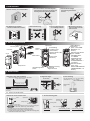
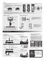
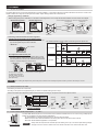
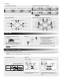
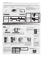
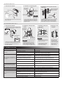
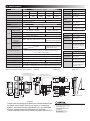
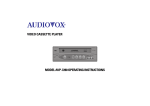
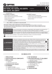
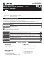
No. 59-1282-6 0808-20 INSTALLATION MANUAL PHOTOELECTRIC DETECTOR AX-70TN, AX-130TN, AX-200TN AX-100TF, AX-200TF < STANDARD > N219 < 4 SELECTABLE BEAM FREQUENCIES > Features < AX-70/130/200TN, AX-100/200TF > • High-performance waterproof structure < AX-100/200TF ONLY > • 4 selectable beam frequencies • Horizontal alignment dial for user-friendliness • LED indicator for fine beam alignment level • Adjustable beam interruption period • D.Q. circuit (Environmental disqualification) • Tamper function • Alarm memory • Optional Accessories : Heating unit (HU-3), Back cover (BC-3), Pole side cover (PSC-3) • UL Listed For Safe Use of the Product ・Read this instruction manual carefully prior to installation. ・After reading, store this manual carefully in an easily accessible place for reference. ・This manual uses the following warning indications for correct use of the product and harm to you or other people and damage to your assets, which are described below. Be sure to understand the description before reading the rest of this manual. WARNING Failure to follow the instructions provided with this indication and improper handling may cause death or serious injury. CAUTION Failure to follow the instructions provided with this indication and improper handling may cause injury and / or property damage. This symbol indicates prohibition. The specific prohibited action is provided in and/or around the figuer. This symbol requires an action or gives an instruction. Do not use the product for purposes other than the detection of moving objects such as people and vehicles. Do not use the product to activate a shutter, etc., which may cause an accident. WARNING Do not touch the unit base or power terminals of the product with a wet hand (do not touch when the product is wet with rain, etc.). It may cause electric shock. Never attempt to disassemble or repair the product. It may cause fire or damage to the devices. Do not exceed the voltage or current rating specified for any of the terminals during installation, doing so may cause fire or damage to the devices. CAUTION Do not pour water over the product with a bucket, hose, etc. The water may enter, which may cause damage to the devices. Clean and check the product periodically for safe use. If any problem is found, do not attempt to use the product as it is and have the product repaired by a professional engineer or electrician. CONTENTS 1. PRECAUTIONS 2. PARTS IDENTIFICATION 3. INSTALLATION 3-1 NOTE 3-2 INSTALLATION METHOD 4. WIRE CONNECTION 5. ALIGNMENT 5-1 OPTICAL ALIGNMENT 5-2 BEAM INTERRUPTION TIME 5-3 4 SELECTABLE BEAM FREQUENCIES * TF ONLY 6. WALK TEST 7. SPECIAL FUNCTION * TF ONLY 7-1 ENVIRONMENTAL DISQUALIFICATION 7-2 ALARM MEMORY 8. OPTIONAL ACCESSORIES 8-1 HEATING UNIT : HU-3 8-2 BACK COVER : BC-3 8-3 POLE SIDE COVER : PSC-3 9. TROUBLE SHOOTING 10. SPECIFICATIONS 1. PRECAUTIONS 2. Do not install the unit where objects moved by the wind such as plants and laundry, which may block the beam. 1. Mount unit only on a solid surface. 3. Prevent direct sunlight from entering into internal receiver. 3 4. A different type of beam should not reach the receiver. receiver 6. Do not install the unit on unsteady surfaces. 5. Avoid aerial wiring. 7. Mount the units more than 1m away from the wall or fence. transmitter 3.3 ft. (1m) transmitter (other model) 2. PARTS IDENTIFICATION Pole-mounting Bracket •Transmitting Condition LED (Transmitter) •Alarm Indicator LED (Receiver) Wiring Hole Unit Base Alarm Memory (Receiver) (See "7-2 ALARM MEMORY * TF ONLY") Selection Dip Switch (See "4 WIRE CONNECTION", "5-2 BEAM INTERRUPTION TIME", and "7-2 ALARM MEMORY * TF ONLY") Selection Switch (See "5-3 4 SELECTABLE BEAM FREQUENCIES * TF ONLY") Terminals Mounting Plate Cover View Finder Monitor Jack (Receiver) Optical Unit Vertical Alignment Screw Waterproof Plug Horizontal Alignment Dial 3. INSTALLATION 3-1. NOTE 1. Detection range and installation 2. Alignment angle Distances between the Receiver and the Transmitter ex) AX-70TN : 70ft.(20m) 3. Pole mounting Vertically Horizontally ・Pole size should be 1 1/4”-1 7/8” (φ32-48mm). (Standard U.S. 1 1/4” or 1 1/2”pipe) about 2.0ft.(60cm) 2.3ft.-3.3ft. (0.7-1m) It is not recommendable to install the units in this way (or direction). In case you do this installation, maximum detection range shall be half of the original detection range. (This is to prevent the attenuation of beam by the edge of the cover.) about 3.3ft. (1m) 10 (±5 ) 180 (±90 ) 3-2. INSTALLATION METHOD 1. Detach the cover and the screw Hood 2. Fix the mounting plate Optical Unit Wall Mounting Screws Mounting Plate Lock Screws Waterproof Plug Mounting Plate Cover Lock Screw Note Unit Base lock Screw When removing the cover, do not put your fingers on the hood, whitch may cause damage. 1) Loosen the cover lock screw to detach the cover. 2) Turn the optical unit and open the waterproof plug. 3) Loosen the unit base lock screw and slide the mounting plate downward to detach the unit base. Pole Lock Screws Wall mounting Pole mounting (1 plate) Pole mounting (2 plate) 3. Wiring Use wires in compliance with the following conditions: 1) Wire diameter: φ4 - 7mm 2) When using any other wires than the above, seal the wiring port with a waterproof agent (silicon, etc.) to prevent water from coming in through the gap. 3) Number of wires: 3 (max.) Cutting Knockout Wiring Hole 2 Wiring Hole 1 Knockout 3 wires can be accommodated in a unit. Lead-in wire should be as below. Figure 1 *Wiring hole 2 needs to be punched with a screw driver, etc. *To have the wiring hole 3, wiring port needs to be cut with a cutter knife, etc. After inserting the wire, seal the wiring port with a waterproof material like silicon for leakage prevention. Figure 2 Figure 3 Wiring guide should be as below. Knockout needs to be opened with a nipper, etc. 5. Alignment and walk test 4. Mount the unit base Waterproof Plug Align the optical axis to the maximum receiving level according to “5-1. OPTICAL ALIGNMENT”. Then, check for the operation with reference to “6. WALK TEST”. Unit Base Lock Screw Push in up to this position Put the cover and tighten the cover lock screw. Make sure that the cover edge has reached the line prepared on the side of the unit base (See the figure left) Side view of the waterproof plug Connect the terminals with reference to “4. WIRE CONNECTION” and slide the unit base into the mounting plate from above, then fasten the unit base mounting screws to fix the unit base. Then, push in the waterproof plug up to the broken line shown in the figure above. Line Screwdriver 4. WIRE CONNECTION Connect respective wires to the terminals shown in the following figure. 1. Terminal [AX-70/130/200TN] < Receiver > Power input 10.5 to 28VDC + − 2. Wiring distance between power supply and detector Note:Non-Voltage contact output Resistive load only Alarm output (N.C.) Non-voltage contact output Contact capacity: 28VDC and 0.2A (max.) < Transmitter > Tamper output : (BE) Model only (it opens when cover is removed) Non-voltage contact output Contact capacity: 28VDC and 0.2A (max.) Tamper output (It opens when cover is removed) Non-voltage contact output Contact capacity: 28VDC and 0.2A (max.) Power input 10.5 to 28VDC ALARM TAMPER + - TAMPER ・Ensure that the wiring distance from the power supply is within the range shown in the table on the right. ・When using two or more units on one wire, the maximum length is obtained by dividing the wire length listed below by the number of units used. Wire size AWG22 (0.33mm2) [AX-100/200TF] < Receiver > Alarm output: (N.C./N.O.) switch (In case of using N.O., contact is not reversed when power supply is off.) Non-voltage contact output N.C. / N.O. selection Swich Contact capacity: 28VDC and 0.2A (max.) N.C./ + − COM. N.O. TAMPER Use the COM. terminal for both alarm output and D.Q. circuit. 3 Power input 10.5 to 28VDC Tamper output (It opens when cover is removed) Non-voltage contact output Contact capacity: 28VDC and 0.2A (max.) OFF ON N.C. ⇔ N.O. 24VDC 1600ft.(500m) 7800ft.(2400m) AWG20 (0.52mm2) 2200ft.(700m) 11400ft.(3500m) AWG18 (0.83mm2) 3600ft.(1100m) 18000ft.(5500m) AWG16 (1.31mm2) 5500ft.(1700m) 26200ft.(8000m) “For UL Listed applications, the units shall be connected to a UL Listed control unit or Listed Burglar Power Supply capable of providing a minimum of 4 hours standby power.” < Transmitter > Tamper output : (BE) Model only (it opens when cover is removed) Non-voltage contact output Contact capacity: 28VDC and 0.2A (max.) Power input 10.5 to 28VDC WARNING N.C. Environmental Disqualification (N.C.) Non-Voltage contact output Contact capacity : 28VDC and 0.2A (max.) Power supply voltage 12VDC + - TAMPER Do not exceed the voltage or current rating specified for any of the terminals during installation, doing so might cause fire or damage to the devices. 5. ALIGNMENT 5-1 OPTICAL ALIGNMENT The optical alignment is an important adjustment to increase reliability. In accordance with the procedure indicated in the items 1. and 2. in this chapter, make sure to align the monitor jack that monitor output nothing to attain the maximum level. 1. Rough alignment by viewfinder ・While looking through the viewfinder, turn the dial to make alignment in such a way that the other detector is at the center of the sights. < Horizontal alignment > * For Horizontal/Vertical alignment, refer to the following illustration. < Vertical alignment > The alignment can be completed. Turn the horizontal alignment dial by fingers to make alignment Turn the vertical alignment dial with a screwdriver to make alignment 2. Checking of the illumination and Fine alignment Checking of the illumination of the Alarm Indicator ・After the rough alignment using the viewfinder, check the light receiving status by the Alarm Indicator. The beam is not properly aiming at the center of viewfinder. View Finder The relation between monitor output and receiving level of optical axis. < Receiver > Alarm Indicator Light interrupting Light receiving ON(red) OFF Alarm Indicator AX-70/130/200TN Fine adjustment with monitor jack ・After checking the receiving level of optical axis by using the alarm indicator, make sure to make fine alignment for both transmitter and receiver with voltmeter until it reaches maximum monitor output over “Good” level. < Receiver / Transmitter > Set the voltmeter range to 5 to 10VDC and connect the voltmeter probes ⊕ and ⊖ to ⊕ and ⊖ of the monitor jack respectively. Note Fair 2.2V Realign Less than 2.2V Monitor output < Receiver > Realignment (example) or more Light interrupting Alarm Indicator ON(red) Good 2.5V or more Excellent 2.9V or more Light receiving fast flicker slow flicker OFF AX-100/200TF Fair 1.0V Realign Less than 1.0V Monitor output or more Good 2.0V or more Excellent 2.5V or more The horizontal / Vertical alignment. When making the adjustment by the monitor jack, be careful not to intercept the optical unit with your hand, the tester pin cord, etc. 5-2 BEAM INTERRUPTION TIME Initial setting is at 50ms for normal work. According to the speed of a supposed target you select one specific setting out of 4 steps. ON [AX-70/130/200TN] Selection Switch 1 2 50 100 250 500 (msec) Set the interruption time adjustment switches of the Receiver according to the speed of the human object to detect. Interruption Switches time 50ms 1:OFF, 2:OFF 100ms 1:OFF, 2:ON 250ms 1:ON, 2:OFF 500ms 1:ON, 2:ON [AX-100/200TF] Selection Dip Switch Running (2.4m/s) Jogging (1.2m/s) Walking (0.5m/s) Slow movement (0.3m/s) 50msec 100msec 250msec 500msec ޓޓޓ 5-3 4 SELECTABLE BEAM FREQUENCIES * TF ONLY The selectable beam frequencies can be used to avoid unwanted crosstalk that can occur when using multiple photobeams for long distance or beam stacking applications. ・To select between 4 separate beam frequencies, use the switch provided. ・Make sure the receiver and transmitter that are facing each other are set to the same channel. ・More than double stacked application is not possible. (CH) Selection Switch Note Always switch the frequencies TWO channels apart when stacking units on top of one another (See following example) . The upper unit is set on channel 1 while the lower is on channel 3.channels 2 and 4 could have also been used. 《EXAMPLE》 1. Long distance protection 2. Double stacked long distance protection receiver receiver transmitter transmitterA receiverA receiverB Ch1 Ch1 transmitterB transmitterC Ch1 Ch1 receiverC Ch3 Ch3 Ch1 Ch1 Ch3 Ch3 Note 3. Perimeter protection Ch1 Ch1 receiver receiver transmitter receiver transmitter transmitter Ch2 Ch2 receiver transmitter transmitter Ch3 Ch3 Ch4 Ch4 More than double stacked apprication is not possible. 4. Double stacked long perimeter protection transmitter(Ch3) transmitter(Ch1) receiver(Ch1) receiver(Ch3) receiver(Ch3) receiver(Ch1) transmitter(Ch2) transmitter(Ch3) transmitter(Ch4) receiver(Ch1) receiver(Ch2) receiver(Ch3) receiver(Ch4) receiver(Ch2) receiver(Ch4) transmitter(Ch1) transmitter(Ch3) transmitter(Ch1) receiver(Ch1) transmitter(Ch2) transmitter(Ch1) transmitter(Ch4) transmitter(Ch3) receiver(Ch3) 6. WALK TEST Make sure to check for the operation after installation. 1. Checking by the Alarm Indicator 2. Walk test receiver < Receiver > B Alarm Indicator C transmitter A If there are reflective things such as a fence, stop at the position C. once and make sure that the detector operates correctly. Make sure that the Alarm Indicator is OFF. If it is illuminated even when the beams are not blocked, make optical alignment again. Note Be sure to conduct a walk test (to block the infrared beam) at the following tree point: A. In front of the Transmitter B. In front of the Receiver C. At the middle point between the Transmitter and the Receiver If the Alarm Indicator is not turned on after beam interception, check for the operation with reference to “9. TROUBLE SHOOTING.” 7. SPECIAL FUNCTION * TF ONLY 7-1 ENVIRONMENTAL DISQUALIFICATION D.Q. will send a trouble signal which indicates the adverse weather condition when the beam strength is being kept more than 40 seconds. adverse weather level > the beam strength > alarm output level < Operating time chart > < Example > [D.Q. + Alarm] Adverse Weather Level Alarm Output Level 40 sec Beam Strength D.Q. ON OFF 2 sec [Alarm Output Cancellation] + + + - - - COM. N.C. (Alarm) N.C. (D.Q.) transmitter receiver Power 12VDC COM. N.C. COM. N.C. Alarm1 } }Alarm2 Control Panel + + - - + Power - 12VDC COM. N.C. COM. N.C. (Alarm) N.C. (D.Q.) }Alarm N.O. Load Power GND transmitter receiver External Relay Control Panel Use the COM. terminal for both alarm output and D.Q. circuit. By using external relay (N.O.), alarm output can be cancelled while D.Q. send signal. 7-2 ALARM MEMORY * TF ONLY This function is used to indicate which detector was activated with alarm memory LED while several detectors are installed in one site. For first 5 minutes after the alarm output, the alarm memory indicator do not light up. Then the alarm memory indicator keep lighting up for 55 minutes. 5 minutes. Alarm memory record is cleared after alarm memory indicator is turned off. < Receiver > < Indicator > < Alarm Memory Indicator > Number of blinking N (times) tells how long it passed over after alarm output. “N” is added one time every 5 minutes. (N=1 ∼ 11) ON Alarm Memory Indicator 4 OFF ⇔ ON (Indicator ON) (Indicator OFF) ON Through the cover Selection Dip Switch If there is an alarm output. < Operating time chart > Alarm Alarm 5 min. 55 min. 4 sec 0.5 sec If it detects the environmental disqualification before 5 minutes of alarm output. ON OFF OFF Alarm Alarm Output Alarm Memory Indicator 5 min. 2 min. 2 min. ※Number of blinking N 55 min. 10 sec FLASHING ON ※Number of blinking N OFF 4 sec 0.5 sec 10 sec 8. OPTIONAL ACCESSORIES 8-1 HEATING UNIT : HU-3 Power voltage of 24VAC/DC is required to use the heating unit. Note In case the same power supply is used for the sensors, wiring distance is required according to the table shown in 3. 1. Cutout of the knockout 2. Direction of the optical unit Cut off the shaded area. Direction of the optical unit Rotate the optical unit approximately 45° away from the knockout area that you cut out in Step 1. Knockout Knockout cutoff section Optical Unit Knockout cutoff side Rear view of the unit base Cut off the knockout of the unit base’s wiring holes located on the side where the optical units of the transmitter and receiver face each other and on its opposite side with a nipper, etc. In the case of the front side, cut off the knockout located on either left or right side only. [Front view of the unit base] 3. Mounting and wiring of the heating unit 4. Connection using the connector Waterproof material (included) Heater Connector Cutouts Heater cutouts Align the heater as shown in the diagram and slide it into place behind the product’s optical unit. Route the heater cables through the heater cutouts and pass them through the wiring holes you cut in Step1. Ensure that the wiring distance from the power supply is within the range shown in the table on the right. When using two or more units on one wire, the maximum length is obtained by dividing the wire length listed below by the number of units used. Pull the heater cables through the wiring holes until there is no slack remaining. Wiring distance Wiring Distance Wire Size AWG18 1000ft. (300m) 2 (0.83mm ) AWG16 1700ft. (500m) (1.31mm2) AWG14 2600ft. (800m) (2.09mm2) Seal the wiring holes with the waterproof material (included) so that there is no gap between the wire and the surrounding plastic. Repeat it for both holes. “UL Listed applications, the heating unit was not investigated with the models AX-70/130/200TN, AX-100/200TF.” When connecting the lead wires to the wiring, make the connection using the supplied connector or soldering. Insert the wires into the connector and tighten the connections with pliers. 5. Mounting of the unit base and optical alignment Unit Base Mounting Screw 8-2 BACK COVER : BC-3 1. Cutout of the knockout 2. Installation of mounting plate 3. Installation of the unit base and the back cover Mounting plate lock screws (for main unit) Back cover lock screw (The same applies to the opposite side.) Unit Base Optional pole bracket (for BC-3) Back Cover Cut with cutter. Pole lock screws (for main unit) Knockout Knockout (The same applies to the opposite side.) Note Do not use pole bracket supplied with the unit Cut off the knockout portion of the back cover with a cutter, etc. Fix the unit base body mounting-plate and the pole bracket for the option supplied with the back cover by using the supplied screws. After mounting the units base, fix the back cover on the pole bracket by using the screws (4 pieces). Align the optical axis and check for the operation, then close the cover. (See “ 3. INSTALLATION “) 8-3 POLE SIDE COVER : PSC-3 1. Cutout of the knockout Outside of the knockout (φ35-48mm : the diameter of a pole) Inside of the knockout (φ32-34mm : the diameter of a pole) Pole Side Cover Cut only the required parts with cutter Cut the perforation with a cutter 25% 2. Installation of the pole side covers Cut the edge of the knockout (outside or inside) with a nipper and then break the knockout portion with a cutter. Also break the center bridge of the pole side cover along with the perforation. 4. Mounting of the unit base Pole side cover Mounting plate lock screws (for main unit) Unit Base Pole lock screws (for main unit) Note 3. Installation of the pole side covers Optional pole bracket (for PSC-3) Do not use pole bracket supplied with the unit Fix the unit base body mountingplate and the pole bracket for the option supplied with the pole side cover by using the supplied screws. Pole side cover lock screw (The same applies to the opposite side.) Note When the pole side cover fix on the pole bracket, make sure the position of the screws. Fix the pole side cover on the pole bracket by using the screws (8 pieces). After mounting the units base, align the optical axis and check for the operation, then close the cover. (See “3. INSTALLATION”) 9. TROUBLE SHOOTING Problem LEDs on the transmitter are not illuminated. Possible Cause Corrective Action Inappropriate power supply voltage Disconnection in power line Check the voltage and make sure that it is between 10.5 and 28VDC. Check the wiring Inappropriate wiring distance or wire diameter See "2. Wiring distance between power supply and detector" of "4. WIRE CONNECTIONS", and check the wiring distance. Inappropriate power supply voltage Check the voltage and make sure that it is between 10.5 and 28VDC. Inappropriate wiring distance or wire diameter See "2. Wiring distance between power supply and detector" of "4. WIRE CONNECTIONS", and check the wiring distance. The beams are reflecting off the floor and Align the optical axis again. If "Alarm Indicator" is not turned on yet, "Alarm Indicator" is not iiluminated remove the reflecting objects or change the installation site. even if the beam is blocked in front of wall of a building, and entering the receiver. the receiver. Not interrupting both upper and lower beams at the Interrupt both upper and lower beams at the same time. same time. Blocking the beam in fron to fot the receiver illuminates the "Alarm Indicator" but does not activate the alarm. Receiving any other beams from other transmitters. Move the receiver to any other place where it does not receive any beam from other transmitters. Signal line short-circuited Check the wiring Alarm contact welded "Alarm Indicator" of the receiver does Optical axis of transmitter and receiver not aligned. not go out. Object blocking the beam between transmitter and receiver Frost, snow or heavy rain cause false alarm Optical alignment not optimized Object blocking the beam between transmitter and receiver Repair the required. Contact the distributor or us. See "5-1 OPTICAL ALIGNMENT" and make realignment. Remove the object or move the unit to a place without any object that may block the beam. See "5-1 OPTICAL ALIGNMENT" and make realignment. See "5-2 BEAM INTERRUPTION TIME"and set an appropriate interruption time Vehicle or plant blocking the beam between transmitter Remove any object blocking the beam and receiver Alarm activated even if the light is not blocked Surface of transmitter/receiver cover soiled Inaccurate optical alignement Inappropriate location of installation Clean the cover (wipe the cover with a soft coth dampened with water or diluted neutral detergent) See "5-1 OPTICAL ALIGNMENT" and make realignment. Change the location ・After above inspections, if there remains any problem, contact our dealer or us immediately. 10. SPECIFICATIONS Name Heating unit Model AX-70TN AX-130TN AX-200TN AX-100TF AX-200TF Model HU-3 Range 70ft (20m) 130ft (40m) 200ft (60m) 100ft (30m) 200ft (60m) Power input 24VAC/DC Maximum arrival distance 700ft (200m) 1300ft (400m) 2000ft (600m) 1000ft (300m) 2000ft (600m) Current draw 420mA(max.) (Per 1 unit) Thermo switch 140°F (60℃) Operating temperature –31°F– +140°F (–35– +60℃) Weight 0.4oz(12g) (Heater (×2)) Packages Heater (×2), Connector (×4), Waterproof agent Photoelectric detector Detection method Infrared beam interruption detection Selectable beam frequency 4 channel Variable between 50,100,250,500msec (4 steps) Power input 10.5-28VDC Current draw (Transmitter+Receiver) 38mA (max.) 41mA (max.) 45mA (max.) 44mA (max.) 48mA (max.) T:17mA+R:21mA T:20mA+R:21mA T:24mA+R:21mA T:6mA+R:38mA T:10mA+R:38mA Alarm output N.C. 28VDC, 0.2A (max.) Alarm period Output N.C./ N.O. 28VDC, 0.2A (max.) 2 sec (±1) nominal D.Q.output Tamper output Alarm indicator (Receiver) Power (Transmitter) Indicator N.C. 28VDC, 0.2A (max.) N.C. : open when cover is removed 28VDC, 0.2A (max.) Alarm : ON (red), Light receiving : OFF Power ON : ON (green), Power OFF : OFF –31°F– +140°F (–35– +60℃) Use the optional heating unit (HU-3) under the environment of –13°F (–25℃) or less minus. 95% max Alignment angle ±90°Horizontal, ±5°Vertical Mounting Indoor/Outdoor, Wall/Pole mounting 22.9oz (650g) IP65 Packages Transmitter (×1), Receiver (×1), Pole bracket (×4), Mounting plate lock screws (×8),Pole lock screws (×8), Wall mounting screws (×4) 【AX-70/130/200TN, AX-100/200TF】 【BC-3】 –31°F– +140°F (–35– +60℃) Weight 5.3oz(150g) (Back Cover (×2)) Packages Back cover (×2), Optional pole bracket (×4), Back cover lock screw (×8) Pole side cover Model PSC-3 Operating temperature –31°F– +140°F (–35– +60℃) Weight 3.9oz(110g) (Pole Side Cover (×2)) Packages Pole side cover (×2), Optional pole bracket (×4), Pole side cover lock screw (×8) 【HU-3】 QTQXGT QTQXGT The diameter of a pole : minΦ1.3(Φ32)-maxΦ1.9(Φ48) Ǿ Ǿ㧦 Ǿ Ǿ㧦 Name 【PSC-3】 The diameter of a pole : minΦ1.3(Φ32)-maxΦ1.9(Φ48) Operating temperature 24.7oz (700g) International protection BC-3 (Indicator will remain lit for 55 minutes, 5 minutes after alarm output) Environment humidity Weight Back cover Model Memory : ON or flicker (red) Alarm memory Operating temperature Alarm : ON (red) Light receiving : flicker (red) or OFF Name Interruption period #EVWCNNGPIVJ Name Unit : inches (mm) < note > These units are designed to detect an intruder and activate an alarm control panel. Being only a part of a complete system, we cannot accept responsibility for any damages or other consequences resulting from an intrusion. These products conform to the EMC Directive 89/336 ECC. OPTEX CO., LTD. (JAPAN) (ISO 9001 Certified by LRQA)(ISO 14001 Certified by JET) 5-8-12 Ogoto Otsu Shiga 520-0101 JAPAN TEL:+81-77-579-8670 FAX:+81-77-579-8190 URL:http://www.optex.co.jp/e/ OPTEX INCORPORATED (USA) TEL:+1-909-993-5770 Tech:(800)966-7839 URL:http://www.optexamerica.com OPTEX (EUROPE) LTD. (UK) TEL:+44-1628-631000 URL:http://www.optexeurope.com