1
{
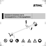
STIHL FS 40, 50
Instruction Manual
English
© ANDREAS STIHL AG & Co. KG, 2015
0458-546-0121-D. VA3.A15.
0000001049_019_GB
Printed on chlorine-free paper
Printing inks contain vegetable oils, paper can be recycled.
Original Instruction Manual
Contents
Guide to Using this Manual
Safety Precautions and Working
Techniques
Approved Combinations of Cutting
Attachment, Deflector, Handle and
Harness
Mounting the Loop Handle
Mounting the Deflector
Mounting the Cutting Attachment
Fuel
Fueling
Starting / Stopping the Engine
Operating Instructions
Cleaning the Air Filter
Adjusting the Carburetor
Spark Plug
Engine Running Behavior
Rewind Starter
Storing the Machine
Maintaining the Mowing Head
Maintenance and Care
Minimize Wear and Avoid Damage
Main Parts
Specifications
Maintenance and Repairs
Disposal
EC Declaration of Conformity
{
FS 40, FS 40 C, FS 50, FS 50 C
2
Dear Customer,
2
Thank you for choosing a quality
engineered STIHL product.
9
10
10
11
14
15
18
20
20
21
21
22
22
23
23
28
29
30
31
32
32
32
It has been built using modern
production techniques and
comprehensive quality assurance.
Every effort has been made to ensure
your satisfaction and troublefree use of
the product.
Please contact your dealer or our sales
company if you have any queries
concerning this product.
Your
Dr. Nikolas Stihl
This instruction manual is protected by copyright. All rights reserved, especially the rights to reproduce, translate and process
with electronic systems.
1
English
Guide to Using this Manual
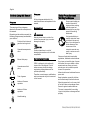
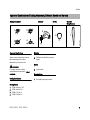
Pictograms
All the pictograms attached to the
machine are shown and explained in this
manual.
Pictograms
The meanings of the pictograms
attached to the machine are explained in
this manual.
Symbols in text
Depending on the model concerned, the
following pictograms may be attached to
your machine.
WARNING
Fuel tank; fuel mixture of
gasoline and engine oil
Warning where there is a risk of an
accident or personal injury or serious
damage to property.
NOTICE
Operate decompression
valve
Manual fuel pump
Caution where there is a risk of
damaging the machine or its individual
components.
Engineering improvements
Operate manual fuel
pump
STIHL's philosophy is to continually
improve all of its products. For this
reason we may modify the design,
engineering and appearance of our
products periodically.
Tube of grease
Therefore, some changes, modifications
and improvements may not be covered
in this manual.
Intake air: Summer
operation
Intake air: Winter
operation
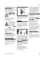
Safety Precautions and
Working Techniques
Some special safety precautions have to be
observed when working
with this power tool
because of the very high
speed of the cutting
attachment.
It is important that you
read the instruction manual before first use and
keep it in a safe place for
future reference. Nonobservance of the
instruction manual may
result in serious or even
fatal injury.
Observe all applicable local safety
regulations, standards and ordinances.
If you have not used this type of power
tool before: Have your dealer or other
experienced user show you how to
operate your unit or attend a special
course in its operation.
Minors should never be allowed to use a
power tool.
Keep bystanders, especially children,
and animals away from the work area.
When the power tool is not in use, shut it
off so that it does not endanger others.
Secure it against unauthorized use.
The user is responsible for avoiding
injury to third parties or damage to their
property.
Handle heating
2
FS 40, FS 40 C, FS 50, FS 50 C
English
The use of noise emitting power tools
may be restricted to certain times by
national or local regulations.
To operate the power tool you must be
rested, in good physical condition and
mental health. If you have any condition
that might be aggravated by strenuous
work, check with your doctor before
operating a power tool.
Persons with pacemakers only: The
ignition system of your power tool
produces an electromagnetic field of a
very low intensity. This field may
interfere with some pacemakers. STIHL
recommends that persons with
pacemakers consult their physician and
the pacemaker manufacturer to reduce
any health risk.
Do not operate the power tool if you are
under the influence of any substance
(drugs, alcohol) which might impair
vision, dexterity or judgment.
Depending on the cutting attachment
fitted, use your trimmer only for cutting
grass, wild growth and similar materials.
It must not be used for any other
purpose because of the increased risk of
accidents and damage to the machine.
Never attempt to modify your power tool
in any way since this may result in
accidents or damage to the machine.
Only use cutting attachments and
accessories that are explicitly approved
for this power tool model by STIHL or
are technically identical. If you have any
questions in this respect, consult a
FS 40, FS 40 C, FS 50, FS 50 C
servicing dealer. Use only high quality
cutting attachments and accessories in
order to avoid the risk of accidents and
damage to the machine.
STIHL recommends the use of genuine
STIHL cutting attachments and
accessories. They are specifically
designed to match the product and meet
your performance requirements.
The deflector on this power tool cannot
protect the operator from all objects
thrown by the cutting attachment
(stones, glass, wire, etc.). Such objects
may ricochet and then hit the operator.
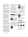
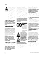
Clothing and Equipment
Wear proper protective clothing and
equipment.
Clothing must be sturdy
but allow complete freedom of movement. Wear
snug-fitting clothing, an
overall and jacket combination, do not wear a
work coat.
WARNING
To reduce the risk of eye
injuries, wear snug-fitting
safety glasses in accordance with European
Standard EN 166. Make
sure the safety glasses
are a good fit.
Wear a face shield and make sure it is a
good fit. A face shield alone does not
provide adequate eye protection.
Wear hearing protection, e.g. earplugs
or ear muffs.
Wear robust work gloves
made of durable material
(e.g. leather).
STIHL offers a comprehensive range of
personal protective clothing and
equipment.
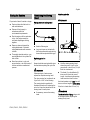
Transporting the Power Tool
Avoid clothing that could get caught on
branches or brush or moving parts of the
machine. Do not wear a scarf, necktie or
jewelry. Tie up and confine long hair
(e.g. with a hair net, cap, hard hat, etc.).
546BA001 KN
Do not lend or rent your power tool
without the instruction manual. Be sure
than anyone using your power tool
understands the information contained
in this manual.
Wear sturdy shoes with
non-slip soles.
Always turn off the engine.
Carry the unit properly balanced by the
drive tube or loop handle.
3
English
In vehicles: Properly secure your power
tool to prevent turnover, fuel spillage and
damage.
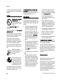
Fueling
To reduce the risk of serious or fatal
burn injuries, check for fuel leakage. If
fuel leakage is found, do not start or run
the engine until leak is fixed.
Before Starting
Gasoline is an extremely
flammable fuel. Keep
clear of naked flames. Do
not spill any fuel – do not
smoke.
Always shut off the engine before
refueling.
Check that your power tool is properly
assembled and in good condition – refer
to appropriate chapters in the instruction
manual.
–
Do not fuel a hot engine – fuel may spill
and cause a fire.
Open the fuel cap carefully to allow any
pressure build-up in the tank to release
slowly and avoid fuel spillage.
Fuel your power tool only in wellventilated areas. If you spill fuel, wipe
the machine immediately – if fuel gets on
your clothing, change immediately.
–
Your power tool comes standard with
either a screw-type or bayonet-type fuel
cap.
After fueling, tighten
down the screw-type fuel
cap as securely as
possible.
After fueling, insert the
fuel cap with hinged grip
(bayonet-type cap) correctly in the opening, turn
it clockwise as far as stop
and fold the grip down.
This reduces the risk of unit vibrations
causing the fuel cap to loosen or come
off and spill quantities of fuel.
4
Check the fuel system for leaks,
paying special attention to visible
parts such as the tank cap, hose
connections and the manual fuel
pump (on machines so equipped). If
there are any leaks or damage, do
not start the engine – risk of fire.
Have your machine repaired by a
servicing dealer before using it
again.
Use only an approved combination
of cutting attachment, deflector,
handle and harness. All parts must
be assembled properly and
securely. To reduce the risk of
injury, never use metal cutting
attachments.
–
The stop switch must move easily to
0.
–
Check smooth action of choke
knob, throttle trigger lockout and
throttle trigger – the throttle trigger
must return automatically to the idle
position. The choke lever must
spring back from the g and <
positions to the run position F when
the throttle trigger lockout and
throttle trigger are squeezed.
–
Check that the spark plug boot is
secure – a loose boot may cause
arcing that could ignite combustible
fumes and cause a fire.
–
Check cutting attachment for
correct and secure assembly and
good condition.
–
Check protective devices (e.g.
deflector for cutting attachment) for
damage or wear. Always replace
damaged parts. Never operate the
unit with a damaged deflector.
–
Never attempt to modify the controls
or safety devices in any way.
–
Keep the handles dry and clean –
free from oil and dirt – for safe
control of the power tool.
–
Adjust the harness and handle(s) to
suit your height and reach.
To reduce the risk of accidents, do not
operate your power tool if it is damaged
or not properly assembled.
If you use a shoulder strap or full
harness: Practice removing and putting
down the power tool as you would in an
emergency. To avoid damage, do not
throw the machine to the ground when
practicing.
Starting the Engine
Start the engine at least 3 meters from
the fueling spot, outdoors only.
Place the unit on firm ground in an open
area. Make sure you have good balance
and secure footing. Hold the unit
securely. The cutting attachment must
be clear of the ground and all other
obstructions because it may begin to run
when the engine starts.
FS 40, FS 40 C, FS 50, FS 50 C
English
Your power tool is a one-person unit. To
reduce the risk of injury from thrown
objects, do not allow other persons
within a radius of 15 meters of your own
position – even when starting.
Do not drop start the power tool – start
the engine as described in the
instruction manual.
Note that the cutting
attachment continues to
run for a short period
after you let go of the
throttle trigger – flywheel
effect.
Check idle speed setting: The cutting
attachment must not rotate when the
engine is idling with the throttle trigger
released.
To reduce the risk of fire, keep hot
exhaust gases and hot muffler away
from easily combustible materials (e.g.
wood chips, bark, dry grass, fuel).
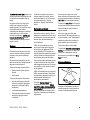
Holding and Controlling the Unit
Always hold the power tool firmly with
both hands on the handles. Make sure
you always have good balance and
secure footing.
546BA002 KN
To reduce the risk of
injury, avoid contact with
the cutting attachment.
Left hand on loop handle, right hand on
control handle, even if you are lefthanded.
Check and correct the idle speed setting
regularly. If the cutting attachment
continues to rotate when the engine is
idling, have the machine checked by
your servicing dealer. STIHL
recommends a STIHL servicing dealer.
Take special care in slippery conditions
(ice, wet ground, snow), on slopes or
uneven ground.
Watch out for obstacles: Roots, tree
stumps or holes which could cause you
to trip or stumble.
During Operation
Make sure you always have good
balance and secure footing.
In the event of impending danger or in
an emergency, switch off the engine
immediately – move the stop switch in
the direction of 0.
Always stand on the ground while
working, never on a ladder, work
platform or any other insecure support.
15m (50ft)
Be particularly alert and cautious when
wearing hearing protection because
your ability to hear warnings (shouts,
alarms, etc.) is restricted.
To reduce the risk of accidents, take a
break in good time to avoid tiredness or
exhaustion.
The cutting attachment may catch and
fling objects a great distance and cause
injury - therefore, do not allow any other
persons within a radius of 15 meters of
your own position. To reduce the risk of
damage to property, also maintain this
distance from other objects (vehicles,
windows). Even maintaining a distance
of 15 meters or more cannot exclude the
potential danger.
Work calmly and carefully – in daylight
conditions and only when visibility is
good. Stay alert so as not to endanger
others.
The correct engine idle speed is
important to ensure that the cutting
attachment stops rotating when you let
go of the throttle trigger.
FS 40, FS 40 C, FS 50, FS 50 C
5
English
Your power tool produces
toxic exhaust fumes as
soon as the engine is
running. These fumes
may be colorless and
odorless and contain
unburned hydrocarbons
and benzol. Never run
the engine indoors or in
poorly ventilated locations, even if your model
is equipped with a catalytic converter.
To reduce the risk of serious or fatal
injury from breathing toxic fumes,
ensure proper ventilation when working
in trenches, hollows or other confined
locations.
To reduce the risk of accidents, stop
work immediately in the event of
nausea, headache, visual disturbances
(e.g. reduced field of vision), problems
with hearing, dizziness, deterioration in
ability to concentrate. Apart from other
possibilities, these symptoms may be
caused by an excessively high
concentration of exhaust gases in the
work area.
Operate your power tool so that it
produces a minimum of noise and
emissions – do not run the engine
unnecessarily, accelerate the engine
only when working.
To reduce the risk of fire, do not smoke
while operating or standing near your
power tool. Note that combustible fuel
vapor may escape from the fuel system.
The dusts, vapor and smoke produced
during operation may be dangerous to
health. If the work area is very dusty or
smoky, wear a respirator.
6
If your power tool is subjected to
unusually high loads for which it was not
designed (e.g. heavy impact or a fall),
always check that it is in good condition
before continuing work – see also
"Before Starting". Check the fuel system
in particular for leaks and make sure the
safety devices are working properly. Do
not continue operating your power tool if
it is damaged. In case of doubt, have the
unit checked by your servicing dealer.
Do not operate your power tool with the
choke lever in the warm start position <
– the engine speed cannot be controlled
in this position.
Always shut off the engine before
leaving the unit unattended.
Check the cutting attachment at regular
short intervals during operation or
immediately if there is a noticeable
change in cutting behavior:
–
Turn off the engine. Hold the unit
firmly and wait for the cutting
attachment to come to a standstill.
–
Check condition and tightness, look
for cracks.
–
Replace damaged cutting
attachments immediately, even if
they have only superficial cracks.
To reduce the risk
of injury from
thrown objects,
never operate the
power tool without
the proper deflector for the type of
cutting attachment
being used.
Clean grass and plant residue off the
cutting attachment mounting at regular
intervals – remove any build up of
material from the cutting attachment and
deflector.
Inspect the work area:
Stones, pieces of metal
or other solid objects may
be thrown more than 15
meters and cause personal injury or damage
the cutting attachment
and property (e.g. parked
vehicles, windows).
Do not continue using or attempt to
repair damaged or cracked cutting
attachments by welding, straightening or
modifying the shape (out of balance).
Special care must be taken when
working in difficult, over-grown terrain.
When cutting high scrub, under bushes
and hedges: Keep cutting attachment at
a minimum height of 15 cm to avoid
harming small animals.
To reduce the risk of injury, shut off the
engine before replacing the cutting
attachment.
This may cause parts of the cutting
attachment to come off and hit the
operator or bystanders at high speed
and result in serious or fatal injuries.
When using mowing heads
Use only the deflector with properly
mounted line limiting blade to ensure the
mowing lines are automatically trimmed
to the approved length.
FS 40, FS 40 C, FS 50, FS 50 C
English
To reduce the risk of injury, always turn
off the engine before adjusting the nylon
line of manually adjustable mowing
heads
Using the unit with over-long nylon
cutting lines reduces the engine's
operating speed. The clutch then slips
continuously and this causes
overheating and damage to important
components (e.g. clutch, polymer
housing components) – and this can
increase the risk of injury from the
cutting attachment rotating while the
engine is idling.
Vibrations
Prolonged use of the power tool may
result in vibration-induced circulation
problems in the hands (whitefinger
disease).
No general recommendation can be
given for the length of usage because it
depends on several factors.
The period of usage is prolonged by:
–
Hand protection (wearing warm
gloves)
–
Work breaks
The period of usage is shortened by:
–
Any personal tendency to suffer
from poor circulation (symptoms:
frequently cold fingers, tingling
sensations).
–
Low outside temperatures.
–
The force with which the handles
are held (a tight grip restricts
circulation).
FS 40, FS 40 C, FS 50, FS 50 C
Continual and regular users should
monitor closely the condition of their
hands and fingers. If any of the above
symptoms appear (e.g. tingling
sensation in fingers), seek medical
advice.
Do not turn the engine over on the
starter with the spark plug boot or spark
plug removed since there is otherwise a
risk of fire from uncontained sparking.
Maintenance and Repairs
Check the fuel filler cap for leaks at
regular intervals.
Service the machine regularly. Do not
attempt any maintenance or repair work
not described in the instruction manual.
Have all other work performed by a
servicing dealer.
Use only a spark plug of the type
approved by STIHL and make sure it is
in good condition – see "Specifications".
STIHL recommends that you have
servicing and repair work carried out
exclusively by an authorized STIHL
servicing dealer. STIHL dealers are
regularly given the opportunity to attend
training courses and are supplied with
the necessary technical information.
Check the condition of the muffler.
Only use high-quality replacement parts
in order to avoid the risk of accidents
and damage to the machine. If you have
any questions in this respect, consult a
servicing dealer.
To reduce the risk of fire, do not service
or store your machine near open flames.
Inspect the ignition lead (insulation in
good condition, secure connection).
To reduce the risk of fire and damage to
hearing, do not operate your machine if
the muffler is damaged or missing.
Do not touch a hot muffler since burn
injury will result.
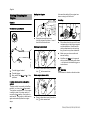
Symbols on Deflectors
STIHL recommends the use of genuine
STIHL replacement parts. These parts
are specifically designed to match your
machine model and meet your
performance requirements.
To reduce the risk of injury from
unintentional engine startup, always
shut off the engine and disconnect the
spark plug boot before performing any
repairs, maintenance or cleaning work. –
Exception: Carburetor and idle speed
adjustments.
An arrow on the deflector (inside and
outside) shows the correct direction of
rotation of the cutting attachments.
7
English
It is important to follow the maintenance
instructions for the Polycut mowing
head.
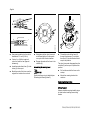
Mowing Head with Nylon Lines
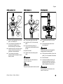
Check the wear limit marks!
Wear limit marks are integrated in the
base of the PolyCut.
000BA019 KN
N
If the raised moldings (1) on the
base of the attachment are worn as
shown in the illustration (above
right), do not continue using the
mowing head. Install a new one.
There is otherwise a risk of injury
from thrown parts of the head.
STIHL PolyCut 6-3 Mowing Head with
Polymer Blades
1
002BA073 KN
To reduce the risk of injury, never use
steel wire in place of the nylon cutting
line.
WARNING
If the wear limit marks are ignored, there
is a risk of the cutting tool shattering and
flying parts injuring the operator or
bystanders.
To reduce the risk of accidents from
shattered blades, avoid contact with
stones, metal and similar solid objects.
Nylon line achieves a soft cut for edging
and trimming around fence posts, trees,
etc. – less risk of damaging tree bark.
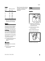
WARNING
Do not continue using the PolyCut 6-3 if
one of the circular holes (1; arrow)
becomes visible or if the projecting rim
(2; arrow) has worn away. Install a new
mowing head.
Check PolyCut blades for cracks at
regular intervals. If a crack is found in
one of the blades, always replace all the
blades.
STIHL FixCut
2
002BA074 KN
Check the wear limit marks!
For mowing unobstructed edges of
meadows (without posts, fences, trees
or similar obstacles).
8
FS 40, FS 40 C, FS 50, FS 50 C
English
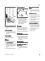
Approved Combinations of Cutting Attachment, Deflector, Handle and Harness
E
IN
/L
ur
hn
Sc
Sc
hn
ur
/L
E
IN
1
1
2
Cutting Attachment
Deflector
2
Handle
5
6
4
7
546BA018 KN
3
Shoulder
Strap/Harness
Approved Combinations
Deflector
Select correct combination from the
table according to the cutting
attachment you intend to use.
5
Deflector with blade for mowing
heads
Handle
WARNING
For safety reasons no other
combinations are permitted – risk of
accidents.
Cutting Attachments
6
Loop handle
Shoulder Strap
7
Shoulder strap may be used
Mowing heads
1
2
3
4
STIHL AutoCut C 5-2
STIHL AutoCut 5-2
STIHL FixCut 5-2
STIHL PolyCut 6-3
FS 40, FS 40 C, FS 50, FS 50 C
9
English
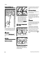
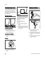
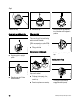
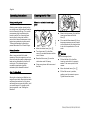
Mounting the Loop Handle
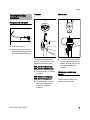
Mounting the Deflector
A
232BA066 KN
1
The loop handle can be adjusted to suit
the height and reach of the operator and
the application by changing
distance (A).
1
2
546BA003 KN
Recommended distance (A):
about 15 cm
Versions with screw (FS 40)
N
Use a screwdriver or the
combination wrench to loosen the
screw (1) on the handle.
N
Slide the handle to the required
position.
N
Tighten down the screw or star knob
so that the handle cannot be rotated
on the drive tube.
4
3
N
Push the deflector (1) over the
clamp (2) as far as stop.
N
Insert the nut (3) in the hex recess in
the deflector – make sure the holes
line up.
N
Insert the screw (4) with washer and
tighten it down firmly.
Versions with star knob (FS 50)
N
Loosen the star knob (2) on the
handle.
546BA005 KN
Adjusting the loop handle
2
546BA004 KN
Your new power tool comes with the
loop handle mounted on the drive tube,
but it must be turned and lined up to suit
your requirements.
545BA004 KN
All versions
N
10
Turn the handle to the vertical
position.
FS 40, FS 40 C, FS 50, FS 50 C
English
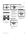
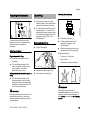
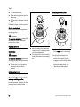
Thrust plate
Mounting the Cutting
Attachment
Block the shaft.
1
Placing power tool on the ground
6
3
546BA016 KN
2
N
Lay your trimmer on its back with
the loop handle and shroud pointing
down and the output shaft facing up.
6
The thrust plate is shipped with the
PolyCut 6-3 and FixCut 5-2. It is only
required for these mowing heads.
STIHL AutoCut 5-2 mowing head,
STIHL AutoCut C 5-2 mowing head
N
Pull the thrust plate (1), if fitted, off
the shaft (2).
STIHL PolyCut 6-3 mowing head,
STIHL FixCut 5-2 mowing head
N
FS 40, FS 40 C, FS 50, FS 50 C
Slip the thrust plate (1) over the
shaft (2) and engage the hex
recess (3) on the external
hexagon (4).
5
N
546BA017 KN
Switch off the engine.
232BA033 KN
N
4
To block the shaft, insert a suitable
tool (5) through the holes (6) in the
deflector and thrust plate – turn the
thrust plate back and forth if
necessary.
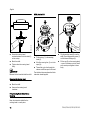
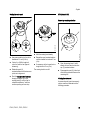
Fitting Mowing Head with Screw
Mounting
Keep the instruction leaflet for the
mowing head in a safe place.
11
English
STIHL AutoCut 5-2
8
4
2
1
7
3
2
5
6
N
Screw the mowing head
counterclockwise on to the shaft (1)
as far as stop.
N
Block the shaft.
N
Tighten down the mowing head
firmly.
NOTICE
Remove the tool used to block the shaft.
N
Fit the spring (1) in the mowing
head (2).
N
Wind the mowing line (3) on to the
spool (4).
N
Thread the nylon line through the
sleeves and fit the spool in the head.
232BA053 KN
3
232BA054 KN
002BA385 KN
1
N
Slip the mowing head (2) over the
shaft (5) and engage hex recess (7)
on the external hexagon (6).
N
Fit the cap (8) on the mowing head
– screw it clockwise on to the shaft
as far as stop and tighten it down
firmly.
The individual steps are described in the
instruction sheet supplied.
Removing the Mowing Head
N
Block the shaft.
N
Unscrew the mowing head
clockwise.
Fitting Mowing Head without Screw
Mounting
Keep the instruction leaflet for the
mowing head in a safe place.
12
FS 40, FS 40 C, FS 50, FS 50 C
English
STIHL PolyCut 6-3
STIHL AutoCut C 5-2
STIHL FixCut 5-2
10
5
8
S
ch
nu
r/L
E
IN
2
11
4
9
E
IN
r/L
nu
ch
1
N
Slip the mowing head (2) on to the
shaft – as AutoCut 5-2.
N
Turn the spool (9) clockwise until
the two arrow heads line up –
secure the spool in this position.
N
N
Insert the cap (8) in the spool, press
it down as far as stop and turn it
clockwise at the same time.
Turn the cap until you feel
resistance and then tighten it down
firmly by hand.
3
1
681BA019 KN
681BA018 KN
5
2
N
Fit the thrust plate on the shaft.
N
N
Insert the nut (10) in the mowing
head.
Slip the thrust plate (2) over the
shaft.
N
N
Screw the mowing head (11)
clockwise on to the shaft (5) as far
as stop.
Place the mowing head on the
thrust plate (2).
N
Block the shaft.
N
Tighten down the mowing head
firmly.
WARNING
If the mounting nut has become too
loose, fit a new one.
NOTICE
Remove the tool used to block the shaft.
232BA074 KN
S
2
WARNING
Collar (see arrows) must engage the
mowing head's mounting hole.
N
Push the thrust washer (3) over the
shaft (1) so it is seated on the base.
N
Block the shaft.
N
Use the combination wrench (5)
(special accessory) to screw the
mounting nut (4) on to the output
shaft and tighten it down firmly.
WARNING
If the mounting nut has become too
loose, fit a new one.
FS 40, FS 40 C, FS 50, FS 50 C
13
English
NOTICE
Remove the tool used to block the shaft.
Remove the mowing head.
STIHL AutoCut
N
Hold the mowing head steady.
N
Unscrew the cap counterclockwise.
STIHL PolyCut
N
Block the shaft.
N
Unscrew the mowing head
counterclockwise.
STIHL FixCut
N
Block the shaft.
N
Use the combination wrench
(special accessory) to loosen and
unscrew the mounting nut
counterclockwise from the output
shaft.
Fuel
Your engine requires a mixture of
gasoline and engine oil.
WARNING
For health reasons, avoid direct skin
contact with gasoline and avoid inhaling
gasoline vapor.
STIHL MotoMix
If your machine is equipped with a
catalytic converter, you must use
unleaded gasoline.
NOTICE
A few tankfuls of leaded gasoline will
greatly reduce the efficiency of the
catalytic converter.
Gasoline with an ethanol content of
more than 10% can cause running
problems in engines with a manually
adjustable carburetor and should not be
used in such engines.
STIHL recommends the use of STIHL
MotoMix. This ready-to-use fuel mix
contains no benzol or lead, has a high
octane rating and ensures that you
always use the right mix ratio.
Engines equipped with M-Tronic deliver
full power when run on gasoline with an
ethanol content of up to 25% (E25).
STIHL MotoMix uses STIHL HP Ultra
two-stroke engine oil for an extra long
engine life.
Use only high-quality two-stroke engine
oil – preferably STIHL HP, HP Super or
HP Ultra, which are specially formulated
for use in STIHL engines. HP Ultra
guarantees high performance and a
long engine life.
MotoMix is not available in all markets.
Mixing Fuel
NOTICE
Unsuitable fuels or lubricants or mix
ratios other than those specified may
result in serious damage to the engine.
Poor quality gasoline or engine oil may
damage the engine, sealing rings, hoses
and the fuel tank.
Engine oil
These engine oils are not available in all
markets.
Use only STIHL 50:1 two-stroke engine
oil for the fuel mix in models with a
catalytic converter.
Mix Ratio
STIHL 50:1 two-stroke engine oil: 50
parts gasoline to 1 part oil
Gasoline
Use only high-quality brand-name
gasoline with a minimum octane rating
of 90 – leaded or unleaded.
14
FS 40, FS 40 C, FS 50, FS 50 C
English
Examples
Gasoline
Liters
1
5
10
15
20
25
Fueling
Preparations
Use a canister approved for storing
fuel. Pour oil into canister first, then
add gasoline and mix thoroughly.
002BA456 KN
N
STIHL engine oil 50:1
Liters
(ml)
0.02
(20)
0.10
(100)
0.20
(200)
0.30
(300)
0.40
(400)
0.50
(500)
Dispose of remaining fuel and cleaning
fluid properly in accordance with local
regulations and environmental
requirements.
Storing Fuel
N
Store fuel only in approved safety-type
fuel canisters in a dry, cool and safe
location protected from light and the sun.
Before fueling, clean the filler cap
and the area around it to ensure that
no dirt falls into the tank.
N
Position the machine so that the
filler cap is facing up.
Fuel mix ages – only mix sufficient fuel
for a few weeks work. Do not store fuel
mix for longer than 30 days. Exposure to
light, the sun, low or high temperatures
can quickly make the fuel mix unusable.
A number of different filler caps are
installed as standard at the factory.
STIHL MotoMix may be stored for up to
2 years without any problems.
Thoroughly shake the mixture in the
canister before fueling your
machine.
WARNING
002BA418 KN
N
Cliplock filler cap (bayonet-type)
Pressure may build up in the canister –
open it carefully.
N
Clean the fuel tank and canister
from time to time.
FS 40, FS 40 C, FS 50, FS 50 C
15
002BA419 KN
001BA224 KN
001BA221 KN
English
Remove the cap.
Threaded filler cap
N
Opening tank cap with hinged grip
Filling up with fuel
N
While holding the cap depressed,
turn it clockwise until it engages in
position.
N
Fold the grip flush with the top of the
cap.
Take care not to spill fuel while fueling
and do not overfill the tank.
16
Closing tank cap with hinged grip
Rotate the cap about 1/4 turn
counterclockwise.
001BA220 KN
Checking security of cap
Grip must be vertical:
N
Fit the cap in the opening – the
marks on the cap and filler neck
must line up.
N
Press the cap down as far as stop.
001BA223 KN
N
Filling up with fuel
Swing the grip to the upright
position.
001BA219 KN
N
N
001BA222 KN
001BA218 KN
STIHL recommends you use the STIHL
filler nozzle for fuel (special accessory).
–
The lug on the grip must fully
engage the recess (arrow).
FS 40, FS 40 C, FS 50, FS 50 C
English
N
Grip the cap – it is properly locked if
it cannot be turned or removed.
If the cap can be turned or removed
N
Place the cap on the opening and
rotate it counterclockwise until it
engages the filler neck.
N
Continue rotating the cap
counterclockwise (about a quarter
turn) – this causes the bottom of the
cap to be turned to the correct
position.
N
Turn and lock the cap clockwise –
see sections on "Closing" and
"Checking security of cap".
001BA227 KN
Bottom of cap is twisted in relation to
top:
Closing screw-type tank cap
N
Place the cap in the opening.
N
Turn the cap clockwise as far as
stop and tighten it down as firmly as
possible by hand.
Bottom of cap twisted
Bottom of cap correctly
positioned
002BA447 KN
Left:
Right:
Opening screw-type tank cap
Take care not to spill fuel while fueling
and do not overfill the tank. STIHL
recommends you use the STIHL filler
nozzle (special accessory).
002BA448 KN
001BA225 KN
001BA226 KN
Filling up with fuel
FS 40, FS 40 C, FS 50, FS 50 C
N
Turn the cap counterclockwise until
it can be removed from the tank
opening.
N
Remove the cap.
17
English
Also use this setting if the engine has
been running but is still cold.
Starting the Engine
Starting / Stopping the
Engine
Cranking
Controls
4
N
Place the unit on the ground: It must
rest securely on the engine support
and the deflector. Check that the
cutting attachment is not touching
the ground or any other obstacles.
N
Make sure you have a safe and
secure footing.
N
Hold the unit firmly on the ground
with your left hand and press down
– do not touch the throttle trigger or
lockout lever.
546BA007 KN
5
Throttle trigger lockout
Throttle trigger
Stop switch with Run and 0 = Stop
positions.
N
Press in the choke lever (5) and turn
it to g at the same time.
Warm engine (warm start)
Function of stop switch and ignition
system
NOTICE
Do not stand or kneel on the drive tube.
5
547BA017 KN
The stop switch is normally in the Run
position, i.e. when it is not depressed:
The ignition is switched on – the engine
is ready to start. If the stop switch is
moved to the 0 position, the ignition is
switched off. The ignition is switched on
again automatically after the engine
stops.
547BA016 KN
1
2
18
N
Cold engine (cold start)
3
1
2
3
Press the manual fuel pump
bulb (4) at least five times – even if
the bulb is filled with fuel.
547BA018 KN
547BA015 KN
Version with Loop Handle
N
Press in the choke lever (5) and turn
it to < at the same time.
FS 40, FS 40 C, FS 50, FS 50 C
English
As soon as the engine runs
Engine does not start in warm start
position <
N
Move the choke knob to g and
continue cranking until the engine
runs.
547BA021 KN
If the engine does not start
547BA020 KN
N
N
Hold the starter grip with your right
hand.
Version without ErgoStart
N
Pull the starter grip slowly until you
feel it engage and then give it a brisk
strong pull.
Version with ErgoStart
N
Make sure the carburetor is correctly
adjusted. The cutting attachment must
not rotate when the engine is idling.
The machine is now ready for operation.
N
Do not let the starter grip snap back.
Guide it slowly back into the housing
so that the starter rope can rewind
properly.
Continue cranking until engine runs.
FS 40, FS 40 C, FS 50, FS 50 C
N
Check that there is fuel in the tank
and refuel if necessary.
N
Check that the spark plug boot is
properly connected.
N
Repeat the starting procedure.
Fuel tank run until completely dry
N
After refueling, press the manual
fuel pump bulb at least five times –
even if the bulb is filled with fuel.
N
Set the choke knob to suit the
engine temperature.
N
Start the engine.
Shut off the engine.
N
NOTICE
N
Check that all settings are correct.
WARNING
Pull the starter grip steadily.
Do not pull out the starter rope all the
way – it might otherwise break.
Press down the throttle trigger
lockout and open the throttle – the
choke knob moves to the run
position F. After a cold start, warm
up the engine by opening the
throttle several times.
N
Move the stop switch in the direction
of 0 – the engine stops – release
the stop switch – it springs back to
the run position.
Other Hints on Starting
Engine stalls in cold start position g or
under acceleration
N
Move the choke knob to < and
continue cranking until the engine
runs.
19
English
If there is a noticeable loss of engine
power
A factory-new machine should not be
run at high revs (full throttle off load) for
the first three tank fillings. This avoids
unnecessary high loads during the
break-in period. As all moving parts
have to bed in during the break-in
period, the frictional resistances in the
engine are greater during this period.
The engine develops its maximum
power after about 5 to 15 tank fillings.
During Operation
After a long period of full throttle
operation, allow the engine to run for a
short while at idle speed so that engine
heat can be dissipated by the flow of
cooling air. This protects enginemounted components (ignition,
carburetor) from thermal overload.
After Finishing Work
Storing for a short period: Wait for the
engine to cool down. Empty the fuel tank
and keep the machine in a dry place,
well away from sources of ignition, until
you need it again. For longer out-ofservice periods – see "Storing the
Machine".
20
4
547BA023 KN
During break-in period
Cleaning the Air Filter
3
N
Reach into the recess (4) in the filter
housing and take out the felt
filter (5).
N
Fit a new felt filter element (5). As a
temporary measure you can knock it
out on the palm of your hand or blow
it out with compressed air. Do not
wash.
2
1
547BA022 KN
Operating Instructions
N
Move the choke lever (1) to <.
N
Turn the screw (2) in the filter
cover (3) counterclockwise until the
cover is loose.
N
Ease the filter cover (3) over the
choke lever and lift it away.
N
Clean away loose dirt from around
the filter.
NOTICE
Replace damaged parts.
N
Fit the felt filter (5) in the filter
housing, make sure it is properly
seated – the arrow points to the
recess.
N
Move the choke lever (1) to <.
N
Fit the filter cover in position,
making sure the screw is square.
Tighten down the screw.
FS 40, FS 40 C, FS 50, FS 50 C
English
N
If the engine is down on power,
difficult to start or runs poorly at idle
speed, first check the spark plug.
N
Fit a new spark plug after about 100
operating hours – or sooner if the
electrodes are badly eroded. Install
only suppressed spark plugs of the
type approved by STIHL – see
"Specifications".
Removing the Spark Plug
N
Shut off the engine.
Adjusting Idle Speed
N
Warm up the engine for about
3 minutes.
Turn the idle speed screw (LA)
slowly clockwise until the engine
runs smoothly – the cutting
attachment must not run.
Cutting attachment runs when engine is
idling
N
Turn the idle speed screw (LA)
counterclockwise until the cutting
attachment stops moving and then
rotate the screw another 1/2 to 3/4
turn in the same direction.
WARNING
If the cutting attachment continues to run
when the engine is idling, have your
machine checked and repaired by your
servicing dealer.
FS 40, FS 40 C, FS 50, FS 50 C
2
547BA041 KN
N
N
Remove the spark plug boot (1).
N
Unscrew the spark plug (2).
N
Clean dirty spark plug.
N
Check electrode gap (A) and
readjust if necessary – see
"Specifications".
N
Rectify the problems which have
caused fouling of the spark plug.
Possible causes are:
1
Engine stops while idling
A
–
Too much oil in fuel mix.
–
Dirty air filter.
–
Unfavorable running conditions.
1
000BA045 KN
The carburetor has been set at the
factory to provide an optimum fuel-air
mixture under most operating
conditions.
000BA039 KN
Checking the spark plug
Spark Plug
0815BA006 KN
Adjusting the Carburetor
WARNING
If the spark plug comes with a
detachable adapter nut (1), screw the
adapter onto the thread and tighten it
down firmly to reduce the risk of arcing
and fire.
21
English
Installing the Spark Plug
N
Screw the spark plug into the
cylinder.
N
Press the boot firmly onto the spark
plug.
Engine Running Behavior
If engine running behavior is
unsatisfactory even though the air filter
is clean and the carburetor is properly
adjusted, the cause may be the muffler.
Have the muffler checked for
contamination (carbonization) by your
servicing dealer.
STIHL recommends that you have
servicing and repair work carried out
exclusively by an authorized STIHL
servicing dealer.
Rewind Starter
To help prolong the wear life of the
starter rope, observe the following
points:
N
Pull the starter rope only in the
direction specified.
N
Do not pull the rope over the edge of
the guide bushing.
N
Do not pull out the rope more than
specified.
N
Do not allow the starter grip to snap
back, guide it back into the housing
slowly – see chapter on "Starting /
Stopping the Engine."
Have a damaged starter rope replaced
by your dealer before it breaks
completely. STIHL recommends that
you have servicing and repair work
carried out exclusively by an authorized
STIHL servicing dealer.
22
FS 40, FS 40 C, FS 50, FS 50 C
English
N
Drain and clean the fuel tank in a
well ventilated area.
N
Dispose of fuel properly in
accordance with local
environmental requirements.
N
Run the engine until the carburetor
is dry – this helps prevent the
carburetor diaphragms sticking
together.
N
N
N
Remove, clean and inspect the
cutting attachment. Coat metal
cutting attachments with corrosion
inhibitor.
Thoroughly clean the machine – pay
special attention to the cylinder fins
and air filter.
Store the machine in a dry and
secure location – out of the reach of
children and other unauthorized
persons.
STIHL AutoCut
Placing power tool on the ground
N
Switch off the engine.
N
Lay your trimmer on its back with
the loop handle and shroud pointing
down and the output shaft facing up.
2
1
232BA007 KN
For periods of about 3 months or longer
Adjusting nylon line
Maintaining the Mowing
Head
546BA016 KN
Storing the Machine
Replacing nylon line
Always check the mowing head for signs
of wear before replacing the nylon line.
N
Hold the rotating mowing head
above the ground – tap it on the
ground once – about 3 cm (1.2 in) of
fresh line is advanced.
N
The blade (1) on the deflector (2)
trims surplus line to the correct
length – avoid tapping the mowing
head more than once at a time.
WARNING
If there are signs of serious wear,
replace the complete mowing head.
The nylon mowing line is referred to as
"nylon line" or "line" in the following.
The mowing head is supplied with
illustrated instructions for replacing the
nylon line. Keep the instructions for the
mowing head in a safe place.
N
FS 40, FS 40 C, FS 50, FS 50 C
If necessary, remove the mowing
head.
Line feed operates only if both lines still
have a minimum length of 2.5 cm (1 in).
If the line is shorter than 2.5 cm (1 in):
WARNING
To reduce the risk of injury, always shut
off the engine before adjusting the
mowing line by hand.
23
English
N
Turn the machine over.
N
Press down the cap on the spool as
far as stop.
N
Pull the ends of the lines out of the
spool.
Assembling the mowing head
1
If the spool is empty, refill with nylon line.
4
2
All other mowing heads
Refer to the instructions supplied with
the mowing head.
2
3
n
ch
S
/L
ur
WARNING
E
IN
1
n
ch
/L
ur
E
IN
To reduce the risk of injury, always shut
off the engine before refilling the mowing
head.
N
Fit nylon line in mowing head as
described in the instructions
supplied.
N
Hold the mowing head steady and
rotate the cap (1) counterclockwise
until it can be removed.
Pull the spool (2) out of the mowing
head (3) and remove the remaining
line.
681BA022 KN
681BA021 KN
N
STIHL FixCut
WARNING
1
Replacing nylon line
S
To reduce the risk of injury, always shut
off the engine before adjusting the
mowing line by hand.
N
Fit the empty spool in the mowing
head.
If the spring (4) has popped out:
N
push it into the spool (2) until it
engages in position with an audible
click.
N
Mount the mowing head – see
"Mounting the Mowing Head".
STIHL AutoCut C 5-2
Disassembling the mowing head and
removing remaining nylon line
In normal operation, the supply of nylon
line in the head is used up almost
completely.
24
FS 40, FS 40 C, FS 50, FS 50 C
English
Winding line onto spool
STIHL AutoCut 5-2
r
nu
ch
S
IN
/L
E
2
Removing remaining nylon line
3
Schnur/LINE 1
1
Schnur/LINE 2
E
IN
/L
r
nu
ch
S
2
1
2
3
Use green-coded nylon line with a
diameter of 2.0 mm (0.08 in).
N
Cut two 2 m (6ft 6in) lengths of
nylon line from the reel (special
accessory).
N
Rotate the spool (2)
counterclockwise until the two arrow
points are in alignment.
N
Push the straight end of each line
through one sleeve (5) in the
mowing head (3) until you feel a
noticeable resistance – and then
continue pushing as far as stop.
FS 40, FS 40 C, FS 50, FS 50 C
N
Hold the mowing head steady.
N
Rotate the spool counterclockwise
until the shortest line is about 10 cm
(4 in).
N
If necessary, cut the longer line to a
length of about 10 cm (4 in).
The mowing head is now full.
681BA008 KN
N
681BA024 KN
681BA023 KN
5
N
Open the mowing head – hold it
steady with one hand and turn the
cap (1) counterclockwise.
N
Disengage the spool (2), take it out
of the mowing head and remove the
remaining line.
Winding line onto spool
A prewound spool (special accessory)
may be used as an alternative to the
following procedure.
25
English
3
2
4
3
5
6
N
Use green-coded nylon line with a
diameter of 2.0 mm (0.08 in).
N
N
Cut two 3 m (9ft 9in) lengths of
nylon line from the reel (special
accessory).
Straighten out the nylon lines and
wind them tightly on to the spool –
one nylon line in each chamber.
N
Engage the ends of the lines in the
notches (2).
N
Insert the ends of each line (3) in the
holes (4) in the spool.
Assembling the mowing head
N
Bend the ends of the lines over the
edge of the holes to form a hook.
NOTICE
Check that the spring is installed (see
"Mounting the Mowing Head").
681BA011 KN
7
681BA010 KN
681BA009 KN
5
6
N
Thread the ends of the lines (6)
through the sleeves (7) and push
the spool (2) into the head so that it
snaps into position.
The nylon lines must disengage from the
notches (5) as the spool is pushed into
position.
N
Pull out the ends of the lines as far
as stop.
N
Mount the mowing head on the
machine.
Replacing Cutting Blades
STIHL PolyCut
Always check the mowing head for signs
of wear before installing new cutting
blades.
26
FS 40, FS 40 C, FS 50, FS 50 C
English
WARNING
If there are signs of serious wear,
replace the complete mowing head.
The thermoplastic cutting blades are
referred to as "blades" in the following.
The mowing head is supplied with
illustrated instructions for replacing the
blades. Keep the instructions for the
mowing head in a safe place.
WARNING
To reduce the risk of injury, always shut
off the engine before installing the
blades.
N
Remove the mowing head.
N
Replace blades as shown in the
illustrated instructions.
N
Mount the mowing head on the
machine.
FS 40, FS 40 C, FS 50, FS 50 C
27
English
Complete machine
Control handle
Air filter
Manual fuel pump (if fitted)
Pickup body in fuel tank
Visual inspection (condition, leaks)
X
Clean
Check operation
X
X
X
Replace
X
X
Check
X
Replace
Clean
Carburetor
Check idle adjustment – the cutting
attachment must not rotate
X
X
Have repaired by servicing dealer1)
Fuel tank
X
X
X
X
Cooling inlets
X
X
Readjust electrode gap
X
Replace after every 100 operating hours
Visual inspection
X
Clean
X
All accessible screws and nuts (not adjustRetighten
ing screws)
Visual inspection
Cutting attachment
1)
28
X
X
X
X
X
Replace
Check tightness
Safety labels
X
X
Readjust idle
Spark plug
as required
X
X
Clean
Check
if damaged
if problem
every 12 months
monthly
weekly
after each refueling stop
before starting work
The following intervals apply to normal operating conditions only. If your daily working time is longer or operating conditions are difficult (very dusty work area, etc.),
shorten the specified intervals accordingly.
after finishing work or daily
Maintenance and Care
Replace
X
X
STIHL recommends an authorized STIHL servicing dealer.
FS 40, FS 40 C, FS 50, FS 50 C
English
Minimize Wear and Avoid
Damage
Observing the instructions in this manual
helps reduce the risk of unnecessary
wear and damage to the power tool.
The power tool must be operated,
maintained and stored with the due care
and attention described in this owner's
manual.
servicing dealer. STIHL dealers are
regularly given the opportunity to attend
training courses and are supplied with
the necessary technical information.
Alterations or modifications to the
product not approved by STIHL.
–
Using tools or accessories which
are neither approved or suitable for
the product or are of a poor quality.
–
Using the product for purposes for
which it was not designed.
–
Using the product for sports or
competitive events.
–
Consequential damage caused by
continuing to use the product with
defective components.
Maintenance Work
–
Damage to the engine due to
neglect or deficient maintenance
(e.g. air and fuel filters), incorrect
carburetor adjustment or
inadequate cleaning of cooling air
inlets (intake ports, cylinder fins).
–
Corrosion and other consequential
damage resulting from improper
storage.
–
Damage to the machine resulting
from the use of poor quality
replacement parts.
–
Spark plug
Parts Subject to Wear and Tear
Some parts of the power tool are subject
to normal wear and tear even during
regular operation in accordance with
instructions and, depending on the type
and duration of use, have to be replaced
in good time. Among other parts, this
includes:
All the operations described in the
"Maintenance Chart" must be performed
on a regular basis. If these maintenance
operations cannot be performed by the
owner, they should be performed by a
servicing dealer.
–
Cutting attachments (all types)
–
Mounting hardware for cutting
attachments (rider plate, nut, etc.)
–
Deflectors for cutting attachments
–
Clutch
STIHL recommends that you have
servicing and repair work carried out
exclusively by an authorized STIHL
–
Filters (air, fuel)
FS 40, FS 40 C, FS 50, FS 50 C
Rewind starter
If these maintenance operations are not
carried out as specified, the user
assumes responsibility for any damage
that may occur. Among other parts, this
includes:
The user is responsible for all damage
caused by non-observance of the safety
precautions, operating and maintenance
instructions in this manual. This includes
in particular:
–
–
29
English
Main Parts
1
2
3
4
5
6
7
8
9
10
11
12
13
14
15
16
17
18
19
#
9
1
2
6
3
4
8
7
5
#
10
19
11 14
12
18
15
16
30
17
546BA015 KN
13
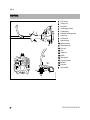
Loop handle
Carrying ring
Stop switch
Throttle trigger lockout
Throttle trigger
Carburetor adjusting screws
Choke lever
Air filter cover
Spark plug boot
Machine support
Manual fuel pump
Tank cap
Tank
Starter grip
Muffler
Mowing head
Line limiting blade
Deflector
Drive tube
Serial number
FS 40, FS 40 C, FS 50, FS 50 C
English
All position diaphragm carburetor with
integral fuel pump
Engine
Fuel tank capacity:
Single cylinder two-stroke engine
FS 40, FS 40 C
Displacement:
Bore:
Stroke:
Engine power to
ISO 8893
Idle speed:
Cut-off speed (rated):
Max. output shaft
speed (cutting
attachment):
27.2 cc
34 mm
30 mm
0.7 kW (1 bhp)
at 8,500 rpm
2,800 rpm
10,000 rpm
10,600 rpm
27.2 cc
34 mm
30 mm
0.8 kW (1.1 bhp)
at 8,500 rpm
2,800 rpm
10,000 rpm
10,600 rpm
Ignition System
Electronic magneto ignition
Spark plug (resistor
type):
Electrode gap:
340 cc (0.34 l)
Dry, without cutting attachment and
deflector
FS 40:
4.4 kg
FS 40 C with ErgoStart:
4.5 kg
FS 50:
4.4 kg
FS 50: with long shaft:
4.5 kg
FS 50 C with ErgoStart:
4.5 kg
FS 50 C with ErgoStart and
long shaft:
4.6 kg
NGK CMR 6 H
0.5 mm
FS 40, FS 40 C, FS 50, FS 50 C
without cutting attachment
FS 40:
FS 40 C with ErgoStart:
FS 50:
FS 50: with long shaft:
FS 50 C with ErgoStart:
FS 50 C with ErgoStart and
long shaft:
FS 40, FS 40 C:
FS 50, FS 50 C:
94 dB(A)
93 dB(A)
Sound power level Lw to ISO 22868
FS 40, FS 40 C:
FS 50, FS 50 C:
Weight
Dimensions
FS 50, FS 50 C
Displacement:
Bore:
Stroke:
Engine power to
ISO 8893
Idle speed:
Cut-off speed (rated):
Max. output shaft
speed (cutting
attachment):
Sound pressure level Lp to ISO 22868
Fuel System
Specifications
107 dB(A)
108 dB(A)
Vibration measurement ahv,eq to
ISO 22867
Handle,
left
FS 40, FS 40 C: 7.0 m/s2
FS 50, FS 50 C: 6.0 m/s2
Handle,
right
6.4 m/s2
5.7 m/s2
The K-factor in accordance with
Directive 2006/42/EC is 2.5 dB(A) for
the sound pressure level and sound
power level; the K-factor in accordance
with Directive 2006/42/EC is 2.0 m/s2
for the vibration measurement.
REACH
1450 mm
1450 mm
1450 mm
1650 mm
1450 mm
1650 mm
REACH is an EC regulation and stands
for the Registration, Evaluation,
Authorisation and Restriction of
Chemical substances.
For information on compliance with the
REACH regulation (EC) No. 1907/2006
see www.stihl.com/reach.
Noise and Vibration Data
Noise and vibration data measurements
include idling and rated maximum speed
with the same duration of exposure.
For further details on compliance with
Vibration Directive 2002/44/EC see
www.stihl.com/vib.
31
English
Users of this machine may only carry out
the maintenance and service work
described in this user manual. All other
repairs must be carried out by a
servicing dealer.
STIHL recommends that you have
servicing and repair work carried out
exclusively by an authorized STIHL
servicing dealer. STIHL dealers are
regularly given the opportunity to attend
training courses and are supplied with
the necessary technical information.
When repairing the machine, only use
replacement parts which have been
approved by STIHL for this power tool or
are technically identical. Only use highquality replacement parts in order to
avoid the risk of accidents and damage
to the machine.
STIHL recommends the use of original
STIHL replacement parts.
Original STIHL parts can be identified by
the STIHL part number, the {
logo and the STIHL parts symbol K
(the symbol may appear alone on small
parts).
Disposal
EC Declaration of Conformity
Observe all country-specific waste
disposal rules and regulations.
ANDREAS STIHL AG & Co. KG
Badstr. 115
D-71336 Waiblingen
confirms that the product described
below
000BA073 KN
Maintenance and Repairs
Category:
Make:
Model:
STIHL products must not be thrown in
the garbage can. Take the product,
accessories and packaging to an
approved disposal site for environmentfriendly recycling.
Contact your STIHL servicing dealer for
the latest information on waste disposal.
Serial identification:
Displacement:
Trimmer
STIHL
FS 40
FS 40 C
FS 40 C-E
FS 50
FS 50-L
FS 50 C
FS 50 C-E
FS 50 C-E L
4144
27.2 cm3
conforms to the provisions of Directives
2006/42/EC, 2004/108/EC and
2000/14/EC and has been developed
and manufactured in compliance with
the following standards in the versions
valid at the time of production:
EN ISO 11806-1, EN 61000-6-1,
EN 55012
The measured and guaranteed sound
power levels were determined according
to Directive 2000/14/EC, Annex V, using
the ISO 10884 standard.
Measured sound power level
all FS 40:
all FS 50:
32
107 dB(A)
108 dB(A)
FS 40, FS 40 C, FS 50, FS 50 C
English
Guaranteed sound power level
all FS 40:
all FS 50:
109 dB(A)
110 dB(A)
Technical documents deposited at:
ANDREAS STIHL AG & Co. KG
Produktzulassung (Product Licensing)
The year of manufacture and serial
number are applied to the product.
Done at Waiblingen, 15.08.2014
ANDREAS STIHL AG & Co. KG
Thomas Elsner
Director Group Product Management
FS 40, FS 40 C, FS 50, FS 50 C
33
0458-546-0121-D
englisch
G
www.stihl.com
*04585460121D*
0458-546-0121-D