1
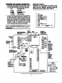
a
raDEMCq
INSTALLATION
INSTRUCTIONS
PRINCIPAL CHANGES-IN THIS ISSUE ARE INDICATED BY MARGIN LINES
GENERAL
INFORMATION
The No. 7620ULF is a self-contained, microprocessorbased, RF alarm communication system consisting of the
No.7620ADV2 Remote Subscriber Equipment (transmitter,
transmitter Interface). a power supply and battery packaged
in a metal cabinet, and is functionally comparable to a digital
communicator in a system connected to a Central
Monitoring Station by telephone line. The No. 7620ULF is
primarily intended for use with a Fire Alarm System (such as
Fire-Lite MS4812). but serves equally well with Burglary
Systems.
This document provides installation and wiring information
for the No. 7620ULF Cabinet Mounted Subscriber Radio. For
information regarding the system description, operating
instructions, and %lectrical specifications, refer to the
No. 7620ADV2 Remote Subscriber Equipment Installation
Instructions (P9916-lVl),
which are included with the
No.7620ULF.
SELECTING A SITE
Before proceeding with the installation procedures, it is
necessary that the installer first verify that the prospective
site is suitable for radio communication with the Master
Station network. This is accomplished by using the FAST
mode of the No. 7920SE, or with the Ademco No. 7915 Field
Alarm Signal Tester (FAST). The FAST Tool is a remote field
strength indicator that receives transmissions from the
network Master Stations. Refer to the No. 7920SE or
No. 7915 operating instructions for information regarding
FAST mode usage.
IMPORTANn
The No. 7620ULF cannot be mounted’.outdoors. lf it is
necessary to mount the antenna outside, follow the
procedures provided on this page for mounting antennas
away from the cabinet. When mounting the antenna, avoid
obstructions such as metal ducts, pipes, foil backed
insulation, etc. as these will adversely affect transmission.
MOUNTING THE ANTENNA
The antenna (No. 7625) can be mounted either remotely, or
directly to the cabinet, and either indoors or outdoors. In
the event that reliable communication cannot be achieved,
optional Nos. 7625~3db. 7674 or 7674-13 antennas may be
used.
Note: The No. 7622CDM Transmitter must be installed
before mounting the antenna. Refer to the procedures
described in the MOUNTING lHE 7622CDM TRANSMmER
section.
Mounting the 7625 or 76253db
Antenna Directly
to the Cabinet:
1. Find the best antenna location by using the FAST Tool.
2. Mount the cabiiet using the procedures described in the
MOUNTING THE 762OULF CABINETsection.
3. Connect the antenna to the cabinet antenna connector.
Mountlng the 7625 or 7625-3db Antenna Away
from the Cabinet:
1. Find the best antenna location by using the FAST Tool.
2. Secure the Ademco No. 7670 Subscriber Antenna
Bracket to the mounting surface using #lO screws.
Connect the antenna to the bracket connector.
3. Connect the antenna cable (50 ohm coaxial cable) to the
bracket connector
and to the cabinet antenna
connector. To avoid signal loss through attenuation,
cable lengths should be 50 feet or less. Use only the
cables listed in Table 1. Tape antenna connections to
seal against moisture.
Using the Optional 7674 or 7674-13 Antenna:
In the event that an acceptable signal strength cannot be
achieved using the No. 7625 antenna, as determined by the
FAST Tool, the optional No. 7674 or No. 7674-13 antenna
may be installed outdoors in a suitable location.
Each of these antennas has directional characteristics, and
must be aimed in the direction which provides the strongest
signal. Once this direction has been determined, using the
FAST Tool, the antenna should be permanently mounted in
precisely the same position. Connect the antenna to the
transmitter using the shortest of the available fifty ohm
coaxial cables which will reach. Tape all connections with a
good quality insulating tape. The No. 7670 BRACKET is not
Table 1.
Ademco Part No.
Cable Lengths
7626-5
5 feet
7626-l 2
12 feet
7626~25LL
25 feet
1
7626-TLL
y
1
50 feet
lmportantl
To ensure the integrity of the security
system, use only the caMes available from ADEMCO.
00 NOT assemble our own extension cables.
DIRECT
MOUNT
TO
CABINET
MOUNTING
v- -*-=
h-4 I Crul
AWAY Fnvm
CABINET
MOUNTING
No. 7674
ANTENNA
N4233V2 71’91
MOUNTING THE No. 762OULF CABINET
The No. 7620ULF cabinet should be mounted indoors. 8nd in
an area where lt will be undisturbed. To facilitate system
testing, the cabinet should also be located in an easily
sccessible area
Cabinet Mountlng
and Wiring PrOCedUrOS:
1. Mount the transformer plate (packed separately) to the
two standoffs using 110 screws.
2. Using the template provided, locate and drill pilot holes
for the four mounting screws.
3. Install the two top comer screws, but leave their heads
slightly protruding from the mounting surface. Slip the
c&net keyslot holes over the screws.
4. Install the bottom two oomer screws, 8nd tighten all
screws securely.
5. Connect the antenna (or antenna cable if antenna is
mounted remotely) to the cabinet antenna connector.
6. Connect the Alarm Control Panel to the No. 7620ULF by
using either shielded or twisted, 22AWG multiconductor
cable. Route the wiring through the cabinet knockout
hole and connect the wires to cabinet TBl terminals as
shown in the Summary of Connections Diagram.
IMPORTANT! Do not exceed wire lengths of 125 feet.
Use oopper wire, not steel wire.
7. Place the batery in the bwer left comer of the cabinet.
8. Route the AC input wires through the cabinet knockout
hole and connect to the two fbating black transformer
wires. DO NOT CONNECT TO POWER SOURCE
AT THIS TIME!
CAUTION!
To prevent
dlslodglng
from sheetrock,
the
No. 7620ULF Should be mounted such that at
le88t the two 8CrSW8 On the door hing8 side
Of the cebinet 8re Secured t0 8 WSII siiud.
I
B SA : APPROVED BY THE NEW YORK CflY BOARD OF
STANDARDS AND APPEAL3 UNDER CALENDAR
NUMBER 86189-SA.
POWERING THE SYSTEM
The No. 7620ULF requires a non-switchable,
continuous, 12OVAC. 6OHz input voltage.
24 hour
power source, using the insulated wire splices provided.
- SPECIAL
7
WARNING!
1. Verify that all internal cabinet connedions are complete.
and be 8uro
that
the trrnsformer
Input
connectIon
8re 8deqUStely
ln8UlSted
to
prevent
l lectrlcsl
Shock.
2. Plug the battery oable into the No. 468CH Power Suppfy
recept8cle.
3. Connect the transformer input wires to a 12OVAC. 60Ht
’
WHEN
~SR POWER
~v”E”
IS
13 A~-~LISU,
APPLIED, THE TRANSFORMER
WIRES
IRES CARRY HIGH VOLTAGE (12OVAC) WHICH
CAN
bN CAUSE SEVERE INJURY
OR DEATH. BE .-.
i.“P
-a
SURE
TO
INSULATE
‘NSULATE
THIS
CONNECTION
i:.
TO
PREVENT
ELECTRICAL
...-ADEQUATELY,
SHOCK TO PERSONNEL.
RSONNEL.
U.L. INSTALLATlON
ff the No. 7620ULF
Is used for Fire Service,
note the followlng
requirements:
1) Channel inputs must be connected to the ‘Alarm’ 8nd
‘System Trouble’ outputs of the Listed Fire Control
Panel. See Note 1.
2) The No. 762OULF must be close-nipple connected to the
Liied Fire Control Panel.
3) ff a digital wmmunic8tor is installed in the Fire Control
Panel, an outdoor and/or long antenna cable length may
be used if:
a. The No. 7620ULF is programmed to monitor the
antenna drr%it at least once every 180 seconds,
and
b. The ‘XMIT OK’ output is connected to the ‘Radio
Fail’ trigger input of the Listed Fire Control Panel.
See Note 2.
INSTRUCTIONS
-
unit enclosure must be protected by 8 Listed Passive
Infrared Detector which is connected to an input zone
programmed for interior burglary protection. The antenna
must be installed indoors and, if an antenna cable is
used. it must be no longer than 12 feet.
4) For Grade A service, the Listed Burglar Alarm Control
Panel must have an integral communicator or a Listed
communicator must be installed. The No. 659EN line
Monitor output must be connected to an input channel of
the No. 762OULF. The ‘XMlT OK’ output must be
connected to an initiating zone of the Listed Control
Panel or communicator,
and this zone must be
programmed for ‘trouble on short circuit’.
Note 7: The No. 7620ULF has been UL Listed for use with
any Listed NFPA71 control panel, provided that the AC
Fail/AC Brown-out supervision of the control panel is
connected to a zone input of the 7620ULF.
Note 2: lf a digital communicator is not installed in the
control panel, and a remote mounting of either the antenna
and/or the 7622CDM transmitter is desired, then supervision
of the interconnecting wires between the 7621AD and the
7622CDM and/or between the 7622CDM and the antenna is
required by connecting the Radio Fault input (pin 22 of the
7621AD) to an appropriate local annunciating means.
SBrViCB,
If the No. 7620ULF I8 Usad for BUrglSry
note the following
requirements:
1) Zone inputs must be connected to dry contact outputs of
a listed Burglar Alarm Control Panel.
2) The No. 7620ULF must be dose-nipple connected to the
listed Control Panel.
3) For G&e B or C servios. the antenna, antenna cable and
2
:-.
MOuNnmnE762zCm-mm
SPECIFICATIONS
1. Removethesauedbmak+fftahhomhottomawerof
theT~mlttorbybendingItrp~dormafowtimes.
2. Connect wires from TE2 to the Tmnamftter a8 folbws:
tB2
TRANSMITTER
7 (vblet)
2 @-urn
6 (+lZVDC)
8 mYI
9 (white)
5 (modulation Input)
lO@ladc)
4 we mJu
3 (monitor output)
11 m&w
3. From the hardware kit provided, place the foam pnds on
the base of the a&net, beneath the Transmluer, near
the top of the cabinet. Place an insufating washer on
top ol each of the two mountfng standoffs and carefully
position the Transmitter on the standoffs and foam
pads, aligning the holes in the bottom cover with the
standoffs. Secure the Transmitter with the screws
provided - two 3/8’ bng screws into the standoffs. and
one 1R bng screw into the top of the Tmnsmitter.
Spedkdbm
for the No.7620ULF are kfentical to those
listed In the No. 7620ADV2 Installation Instructions
(included wlth the 762OULF). with the l ddttiin of the
phyalcal size of the No. 7620ULF cabinet. whbh lx
Cabinet DImmalone: lr L x lZ W x 4.0. Wt: 16 bs.
PANEL
Pfogrummlng
Note:
When programming the PROM. program zone 6 for
inverted operation, since terminal 9 (AC SUPV) is
I normally high.
SUMMARY OF CONNECTIONS DIAGRAM
3
Regular maintenance and inspection (at least annually) by the installer and frequent testing by the user are
vital to continuous satisfactory operation of any alarm system.
The installer should assume the responsibility of developing and offering a regular maintenance progrti to
the user as well as acquainting the user with the proper operation and limitations of the alann system and its
component parts. Recommendations must be included for a specific program of frequent testing (at least
weekly) to insure the system’s proper operation at all times.
FEDERAL COMMUNICATIONS
COMMISSION
.-.
(FCC) STATEMENT
This equipment has been tested to FCC requirements and has been found acceptable for use. The FCC requires the
following statement for your information:
This equipment generates and uses radio frequency energy and if not installed and used properly, that is, in strict
accordance with the manufacturefs instructions, may cause interference to radio and television reception. It has been
type tested and found to comply with the limits for a Class B computing device in accordance with the specifications in
Part 15 of FCC Rules, which are designed to provide reasonable protection against such interference in a residential
installation. However, there is no guarantee that interference will not occur in a particular installation. ff this equipment
does cause interference to radio or television reception. which can be determined by turning the equipment off and on,
the user is encouraged to try to coned the interference by one or more of the following measures:
9 lf using an indoor antenna, have a quality outdoor antenna installed.
Reorient the receiving antenna until interference is reduced or eliminated.
Move the receiver away from the transmitter interface.
Move the antenna leads away from any wire runs to the transmitter.
Plug the transmitter’s power source into a different outlet so that the transmitter and the receiver are on different
branch circuits.
If necessary, the user should consult the dealer or an experienced radio/television technician for additional
suggestions. The user or installer may find the following booklet prepared by the Federal Communications Commission
helpful:
‘Interference Handbook’
This booklet is available from the U.S. Government Printing Office, Washington, DC 20402. under Stock No. 004-OOOl
l
l
l
00450-7.
The user shall not make any changes or modifications
to the equipment unless authorized by the installation
fnstructions or User’s Manual. Unauthorized changes or modifications could void the user’s authority to operate the
equipment.
LIMITED
.n
WARRANTY
Alarm Device Manufacturing Company, a Division of Pittway Corporation, and its divisions, subsidiaries and affiliates
(Seller). 165 Eileen Way. Syosset. New York 11791, warrants its products to be in conformance with its own plans and
specifications and to be free from defects in materiak and workmanship under normal use and service for 16 months
from the date stamp control on the product or, for products not having an Ademco date stamp, for 12 months from date of
original purchase unless the installation instructions or catalog sets forth a shorter period, in which case the shorter
period shall apply. Seller’s obligation shall be limited to repairing or replacing, at its option, free of charge for materials or
labor, any part which is proved not in compliance with Seller’s -specifications or proves defective in materials or
workmanship under normal use and service. Seller shall have no obligation under this Limited Warranty or othemise if the
product is altered or improperly repaired or serviced by anyone other than Ademco iactory setvice. For warranty service,
return product transportation prepaid, to Ademco Factory Service, 165 Eileen Way, Syosset, New York 11791.
THERE ARE NO WARRANTIES. EXPRESS OR IMPLIED, OF MERCHANTABILlIY. OR FlTNESS FOR A PARTICULAR
PURPOSE OR OTHERWISE. WHICH EXTEND BEYOND THE DESCRIPTION ON THE FACE HEREOF. IN NO CASE
SHALL SELLER BE LIABLE TO ANYONE FOR ANY CONSEOUENTlAL OR INCIDENTAL DAMAGES FOR BREACH OF
THIS OR ANY OTHER WARRANTY, EXPRESS OR IMPLIED. OR UPON ANY OTHER BASIS OF LlABlLfTY
WHATSOEVER, EVEN IF THE LOSS OR DAMAGE Ls CAUSED BY THE SELLER’S OWN NEGLIGENCE OR FAULT.
Seller does not represent that its product may not be compromised or circumvented; that the product will prevent any
personal injury or property loss by burglary, robbery, fire or otherwise; or that the product will in all cases provide
adequate warning or protection. Buyer understands that a properly installed and maintained alarm may only reduce the
risk of a burglary, robbery or fire without warning, but it is not insurance or a guarantee that such will not occur or that
there will be no personal injury or property loss as a result. CONSEOUENTLY. SELLER SHALL HAVE NO LlABlLflY FOR
ANY PERSONAL INJURY. PROPERTY DAMAGE OR OTHER LOSS BASED ON A CLAIM THE PRODUCT FAILED TO
GIVE WARNING. However, if Seller is held liable, whether directly or indirectly, for any loss or damage arising under thii
Limited Warranty or otherwise, regardless of cause or origin, Seller’s maximum liability shall not in any case exceed the
purchase price of the product, which shall be the complete and exclusive remedy against Seller. This warranty replaces
any previous warranties and is the only warranty made by Seller on this product. No increase or alteration, written or
verbal, of the obligation of this Limited Warranty is authorized.
n
I
AlARM DEVICE MANUFACTURING COA DMSON OFPITtWAY -TlCN
165 Eileen Way,, Syosset, New York 11791
N4233V2 7/01
copyr#eOllnn
PmwAYcoRfoRAnoN