1
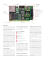
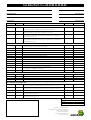
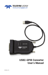
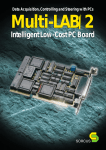
Serial communication with PCs
Multi-COM
The intelligent 6-channel serial PC board
1
Multi-COM
The communication allrounder
Modern-day automation technology includes
numerous tasks excellently suited for PC pro-
Sophisticated protocol handling may substantially downgrade a PC’s performance,
cessing. However, the two lonely RS-232
especially when more than one interface has
standard interfaces with which a PC usually
provides do not exactly predestine it for so-
to be served simultaneously. If in addition to
this, real-time requirements also apply for
■ Intelligent PC board with its own
CPU and peripherals
phisticated communication services. More-
certain processes, the usual PC standard
■ The board’s local CPU works in
over, it is mostly the more powerful variants
of the RS-422 or RS-485 type which are re-
hardware/operating system configuration
will definitely soon come up against its limits.
parallel with the PC’s CPU
■ Available with 486 or 586 CPU, up
quired for industrial purposes, with electrical
In cases like this, the most expedient techni-
isolation where necessary. In place of absolute voltage levels, these latter work with dif-
cal option is to assign time-critical tasks and
communication sequences to a subsystem
ferential voltages, thus rendering them less
operating in parallel, thus freeing sufficient
susceptible to interference as well as enabling them to bridge significantly longer dis-
computing capacities on the PC for the user
interface to save, evaluate and graphically
■ Watchdog, NMI and RAM buffering logic on-board
tances.
edit the results.
■ 10 timers, each with interrupt ca-
Block diagram of the Multi-COM board
Special characteristics
to 133 MHz
■ Up to 34 MByte RAM: DRAM (8 or
32 MByte) and bufferable SRAM
(512 kByte or 2 MByte)
pability
■ Time and date (real-time clock)
■ 6 serial interfaces:
async, sync, HDLC, monosync,
bisync, and other protocols pos-
RAM
sible (baudrate generator and
St1
S-Link
ROM
configurable
SCC
(customer-specific
as well):
RS-232, RS232 iso., RS-422, RS-
S-Link
EEPROM
DPLL for each channel)
■ 5 hardware interfaces individually
422 iso., RS-485, RS-485 iso.,
20 mA iso., CAN iso., PROFIBUS
iso., optical-fiber link
■ 1 RS-232 interface
S-Link
486-CPU
■ OsX real-time multi-tasking operating system on-board (in the
SCC
Watchdog
Timer
Clock
Interrupt Controller
S-Link
EPROM or in the Flash EPROM)
■ Drivers for MS-DOS, Windows
3.x, Windows 95, 98 and NT included in the package
S-Link
SCC
■ Communication protocols available, e.g. 3964/R
St2
RS-232
■ Libraries for developing user protocols included in the scope of
delivery
St3
■ 100 % compatible with MODULAR-4/486 with 2 or 3 M-COM-2
modules
■ Short PC board for 16-bit ISA slot,
PC interface
2
option for stand-alone operation
(without PC)
Local CPU,
Temperature and fan
up to 133 MHz
10 timers
monitoring
5 multi-purpose
serial interfaces,
configurable
with S-Links
Possible physical
interfaces:
■ RS-232 and RS-232 iso.
Real-time
■ RS-422 and RS-422 iso.
multi-tasking
operating system
■ RS-485 and RS-485 iso.
■ 20 mA iso.
■ Optical-fiber link
■ CAN iso.
■ PROFIBUS iso.
■ etc.
RS-232
up to
34 MByte RAM
Clock, watchdog
Intelligent basis
The Multi-COM board for the ISA bus contains a complete computer with comprehensive peripherals on a PC expansion board.
The board can work independently of the PC,
an option for implementing a fiber-optic inter-
of SORCUS boards, is the Multi-COM board’s
face. The S-Links’ job is to match the respec-
compatibility with the widely used MODULAR-4/486 boards from SORCUS. The Multi-
tive signal levels and to provide electrical
isolation for the interfaces. A total of five S-
COM board basically corresponds to a
Links can be plugged on.
sible (up to 8 boards in one PC).
A 486 or 586 CPU (clock frequencies cur-
MODULAR-4/486 board, which is fitted with
three M-COM-2 communication modules.
S-Links for the Multi-COM
The serial interfaces have been implemented
rently up to 133 MHz) operates on the Multi-
■ RS-232, RS-232 iso.
COM board; this CPU can be used for processing communication protocols, for ex-
with a total of 3 SCC building blocks (Z85C30
resp. Z85230; extended version with larger
■ RS-422, RS-422 iso.
FIFOs). And a programmable quartz oscillator
ample. A static and/or dynamic RAM serves
■ RS-485, RS-485 iso.
for storing the communication programs and
for buffering transmit/receive data. The board
for the communication interfaces is additionally provided on the Multi-COM.
■ 20 mA (current loop)
is available with a max. RAM size of 34
■ Optical fiber
MByte. An EPROM contains the Multi-COM
board’s operating system. A watchdog timer,
■ CAN iso. (CAN-controller incl.)
monitoring features for the fan, CPU-tem-
■ PROFIBUS iso. (Slave-controller incl.)
multi-tasking operating system for up to 1024
perature and operating voltage ensure an appropriate response to any error occurring. For
■ SSI iso. (2 channels)
tasks. This operating system is used on all
SORCUS boards and is excellently suited not
meaning genuine parallel processing is pos-
example, important data can still be saved in
the event of a power loss. 10 timers, each
with interrupt capability, are also provided, as
is a real-time clock for date and time (likewise
bufferable). The Multi-COM board can also
be run in stand-alone mode.
Configurable interfaces
The board contains a total of 6 serial communication interfaces and can be used for even
the most complex communication jobs. For
instance, it can be equipped with RS-232, RS422, RS-485, CAN, etc. since the communication interfaces can be configured channel
by channel using plug-on micro-modules,
also referred to as S-Links. There is likewise
Thus all existing programs are compatible,
and can also be used on the Multi-COM
board.
The board’s EPROM contains a real-time
The sixth serial interface is a complete RS232 interface with all modem control lines.
Each interface possesses its own baudrate
generator and a DPLL, with the following operating modes: asynchronous, synchronous,
HDLC, SDLC, monosync, and bisync. A basic
program for buffered serial communication is
available for synchronous and asynchronous
communication tasks. And numerous communication protocols are already available,
too, such as 3964/R, etc.
Compatible with MODULAR-4/486
A special advantage, particularly for those
users already familiar with the programming
only for communication jobs but also for
other functions as well: for example, in addition to communication activities, further realtime programs for open- and closed-loop control as well as monitoring functions can be
utilized, such as digital PID controllers, FastFourier transformations, etc. There is an option for writing your own programs intended
to run as a task on the Multi-COM, using the
familiar PC development environments, without the need for a specific development tool.
Drivers for MS-DOS, Windows 3.x, Windows
95, 98 and Windows NT are also included in
the Multi-COM board’s scope of delivery, as
are libraries and DLLs for all commonly used
high-level languages.
3
Multi-COM
Technical data
CPU
586 (133 MHz) or 486 DX2/66
RAM
Max. 34 MByte
static: 512 kByte or 2 MByte (battery-bufferable)
dynamic: 8 MByte or 32 MByte
ROM
EPROM or Flash-EPROM, up to 512 kByte
EEPROM
128 words, serial
Timers
3 timers with a width of 16 bits, programmable input frequency 1 MHz, 2.5 MHz or 10 MHz,
with interrupt capability; 6 timers in the SCCs and one in the real-time clock
Serial interfaces
6, of which 5 configurable with S-Link (to 62-pin D-Sub connector); 1 RS-232 with all modem control
lines (to 3-pin Mini-DIN plug connector and 20-pole plug connector) SCC 85C30 resp. ESCC 85230,
programmable quartz oscillator
Max. Baudrate
1.2 MBaud (async.), 5 Mbits/s (sync.), applies for EM-2224 and for EM-2592, see last page
S-Link slots
5
Interrupts
Max. 15, some of them also available externally
Voltage
Two response thresholds (4.8 and 4.65 V), NMI-triggering, buffering of RAM and real time clock
monitoring
Temperature
The CPU temperature is measured and monitored (with interrupt triggering)
monitoring
Fan monitoring
Speed monitoring with interrupt triggering and software-based fan control
PC interface
16-bit parallel, bidirectional, with interrupt capability (locally and to the PC)
Clock
Date (day, month, year, weekday) and time (hours, minutes, seconds)
bufferable with external battery, interrupt capability (1/64 sec., 1 sec, 1 min., 1 h)
Multi-tasking
Included in the board’s EPROM
operating system
With real-time capabilities, max. 1024 tasks, interrupt tasks, timer-initiated tasks, and non-interrupt tasks
Power consumption
+5 V (measured with 586-133 MHz, fan and LED off, without S-Links)
+12 V
0.2 mA
–12 V
0.2 mA
–5 V
Dimensions
Board (measured without slot plate and D-Sub plug connector)
Compatibility
Temperature (optional)
Humidity (not condensing)
4
1.8 A
not connected
106 mm x 158 mm
0 to 55 °C (70°C)
5 to 95 %
S-Links
for Multi-COM
SL-232S
SL-232i
SL-232A/i
be configured. Installation and/or
replacement of S-Links can be
• RS-232 up to 220 kBaud
• RS-232 isol. up to 220 kBaud
• RS-232 up to 220 kBaud
performed by the customer. S-
• Modem control lines: TMT,
RCV, RTS, CTS, DTR, DSR, RI,
• Isol. modem control lines:
TMT, RCV, RTS, CTS
• Modem control lines: TMT,
RCV, RTS, CTS, DTR, DSR, RI,
The Multi-COM provides five
slots for S-Links. S-Links are plugon micro-modules with a standard connection pattern for serial
interfaces, which enables all
commonly used signal levels to
Links are available with or without electrical isolation. And there
is also an option for plugging on a
fiber-optic S-Link. S-Links are automatically recognized by the
Multi-COM board, and the serial
DCD
• Additional functions:
– CTS as clock input
– RTS as clock output
• Additional functions:
– RI as clock input
– CTS as clock input
DCD
• Additional functions:
– Additional EXT RS-232 line as
clock input 1
– RTS as clock output
– RI as clock input 2
interfaces concerned are initialized appropriately.
SL-232A/o
SL-422
SL-422i
SL-485
• RS-232 up to 220 kBaud
• RS-422 up to 10 MBaud
• RS-422 isol. up to 10 MBaud
• RS-485 up to 12 MBaud
• Modem control lines: TMT,
RCV, RTS, CTS, DTR, DSR, RI,
• Modem control lines: TMT,
RCV, RTS, CTS
• Modem control lines: TMT,
RCV, RTS, CTS
• Switchover from transmit to
receive either under software
• Additional functions:
• Termination resistors can be
control, or automatically (e.g.
DCD
• Additional EXT RS-232 line as
clock output
– CTS as clock input
– RTS as clock output
switched into circuit on the SLink
for SDLC/HDLC)
• Additional functions:
– CTS as clock input
– RTS as clock output
SL-485i
SL-20MA
SL-LWL
SL-CANi
• RS-485 isol.
• 20 mA isol. up to 38.4 kBaud
• Current loop
• Connection for plastic (SL-
• With its own Intel CAN controller
• Up to 12 MBaud
• Suitable for PROFIBUS
• Additional TTL output indicates transmit/receive, e.g.
for ext. transceiver
• 2
constant-current
sources
provided by the S-Link
• Can be passively or actively
configured (if passively, then
electrically isolated)
LWL/P) or glass fiber-optic link
(SL-LWL/G)
• Transmission rate of up to
1 Mbits/s
• Cable length up to 1000 m
• 11-bit and 29-bit identifiers
• JIS plug connector system
from Toshiba
• Electrically isolated from the
CAN bus
• Including software
5
Programming
High-level-language libraries and real-time
■ 5 to 8 data bits
■ 1, 1.5 or 2 stop bits
Portability
All the Multi-COM’s communication interfaces can be operated with a wide variety of
■ With or without parity (even or odd)
for the various PC operating systems, which
protocols. Those available from SORCUS
include, for example, 3964/R, GE Fanuc, and
■ Handshake per XON/XOFF or with RTS/
CTS
means that a particular application program
(once it has been developed) can easily be
Bosch LSV2.
■ Baudrates of 110 to 115,200 Baud
ported onto a different operating system.
There is also an option for developing your
own protocols. Each serial interface provides
■ Size of the transmit and receive buffers
can be set
Scope of delivery
Protocols
The functionality of the libraries is the same
All high-level-language libraries, plus the cor-
its dedicated baudrate generator and a DPLL.
The possible operating modes are as follows:
asynchronous, synchronous, HDLC, SDLC,
An application program or a superimposed
protocol software package accesses the ba-
responding drivers, are included in the
boards’ scope of delivery. The current library
Monosync, and Bisync. When the appropri-
sic communication facility with function calls.
versions are also available at any time in the
ate S-Links are plugged on, PROFIBUS and
CAN can also be implemented. For this
Basic communication functions can be utilized both by PC and real-time programs on
Internet (www.sorcus.com), free of charge.
The operating systems and compilers sup-
purpose, SORCUS supplies ready-to-use
the board. All the requisite commands are
ported are included in the listing below, to-
communication programs, which facilitate
integration into the software.
included in the high-level-language libraries
supplied with the board. You can use similar
gether with their versions. If the compiler
you’re using is not mentioned there, please
libraries for the Multi-
get in touch with SORCUS.
COM board as for the
MODULAR-4/486
board.
High-level-language
libraries
These offer the operator a user-friendly interface for communicating from the PC with
Multi-COM boards and
Operating systems and programming
languages supported:
MS-DOS
■ Borland C (as from Version 3.1)
■ Microsoft C (as from Version 8.0)
■ Watcom C (as from Version 10.0)
■ Borland Pascal (as from Version 6.0);
also Protected Mode
are available for a variety of programming
languages, like C, Pascal and BASIC, and for
The SL-CANi CAN bus S-Link
Synchronous and
communication
different operating systems, such as MSDOS, Windows 3.x, Windows 95, 98 and
asynchronous
A basic program (CQ6) for buffered serial
communication is available for synchronous
and asynchronous communication jobs. You
can implement user-specific protocols very
easily on the basis of this software. Basic
communication is set up on the PC using a
utility program, and installed on the MultiCOM board. At the bottommost level, the
CQ6 supports the following settings (e.g. for
asynchronous communication):
6
Windows NT. You can serve up to eight
boards from one library.
The libraries handle the following tasks:
■ configuring the board
■ loading real-time programs onto the board
■ data exchange between board and PC
■ error handling
■ interrupt handling
Windows 3.x
■ Borland C (as from Version 3.1)
■ Borland Pascal (Version 7.0)
■ Borland Delphi (as from Version 1.0)
■ Microsoft Visual Basic
(as from Version 3.0)
■ Microsoft Visual C (as from Vers. 1.0)
■ Watcom C (as from Version 10.0)
Windows 95, 98 and Windows NT
■ Microsoft Visual C (as from Vers. 4.0)
■ Borland C (as from Version 5.0)
■ Microsoft Visual Basic (as from Vers. 4.0)
■ Borland Delphi (as from Version 2.0)
■ DASYLab
Under preparation:
■ LabView drivers (1Q99)
programming, protocols, CAN
user, since you can access Borland’s and
Microsoft’s standard compilers (Pascal or
Structure of real-time programs
All SORCUS boards provide their own microprocessor running an operating system with
C++) during programming. A specific devel-
real-time capabilities: OsX. This enables
genuine parallel processing with the PC to be
opment environment is not necessary.
that of a DOS program, except that the program code has been subdivided into what are
implemented, which is more or less essen-
Developing your own programs
tial if data are to be acquired and processed
in real time, especially when modern-day PC
To develop your own real-time programs, you
have to proceed in three steps:
Real-time programming
called task procedures. Task procedures can
operating systems like Windows 98 or NT
are being used. Data-acquisition and communication tasks can be run on the board in com-
1. Enter and compile the real-time program
concerned under Microsoft or Borland
plete independence of the PC, thus freeing
your PC to handle other tasks, like visualization and storage jobs.
A real-time program’s structure resembles
C++ or Borland Pascal.
2. Transfer the program onto the Multi-
The OsX multi-tasking operating system en-
COM board.
be called from other tasks on the board or
from the PC as well, e.g. to start or abort
transmit or receive functions. In addition to
the task procedures, the program also comprises what are called the parameter area and
the data area. The parameter area will normally contain configuration and parameterizing data definable by the user, like baudrate,
parity, etc. The data area can be used to accommodate the user data.
As with the task procedures, here too, other
ables more than one process (task) to be executed simultaneously on a single board.
3. Test and debug the real-time program
tasks on the board and the PC can very easily
Real-time programs running as tasks on the
with the Borland source code debugger
board are very easy to program for you as the
(remote debugging).
access parameters and data. The Multi-COM
board’s libraries provide a variety of functions
for this purpose.
The completely compiled real-time program
can be transferred onto the Multi-COM board
Call
User data
either with the PC utility programs supplied
Task 3
Task 2
Transmission
object 2
M049TASK
calls associated
procedure/task
or from one of the user programs by means
of the PC libraries supplied.
Transmission
object 3
Task 4
Debugging real-time programs
You can use the ‘Turbo-Debugger’ from
Borland to test the real-time program developed exhaustively. This debugger enables a
real-time program to be debugged just like a
Reception
object 4
PC program, at the source code level. All the
Task 1
Task x
M049TASK
Turbo-Debugger’s
features,
such
as
breakpoints, watch variables, etc. are of
course available for this purpose.
Multi-COM
Transmission object x
Reception object 1
CAN
You must install the M049TASK driver soft-
SL-CANi
with CAN-Controller
SL-CANi receives
message and
calls M049TASK
CAN controller on the S-Link, M049TASK
CAN bus
MESSAGE-X
ware supplied on the Multi-COM for operating the SL-CANi S-Link. Together with the
MESSAGE-1
MESSAGE-Y
ensures that messages are received and
transmitted over the CAN bus. The application
software
communicates
with
Messages are sent via the CAN bus. SL-CANi receives and transmits messages. The messages are supplied
from and to M049TASK. M049TASK passes on the user data received from the associated applications, or
M049TASK by function calls, which can be
made both from the PC and from the board
forwards user data to the associated applications.
(in real-time).
7
Fax Order Form to ++49-(0) 62 21-32 06-66
Company
Date
Name/Department
Please print name
P.O.Box/Street
Ordering No.
City/Post Code
Signature/Stamp
Ordering No.
Qty.
Brief description
Price/piece
Multi-COM with 6 serial interfaces (S-Links must be ordered separately.)
EM-2140
Multi-COM: intelligent PC board with a 486-DX2 CPU (66 MHz internal),
512 kB static RAM, including fan, manual and connector
EM-2173
Multi-COM: intelligent PC board with a 586-133 CPU (133 MHz internal),
2 MB static RAM, including fan, manual and connector
EM-2224
Multi-COM: intelligent PC board with a 586-133 CPU (133 MHz internal),
ESCC 85230, 10 MB RAM (2 MB static and 8 MB dyn.), including fan,
manual and connector
EM-2592
Multi-COM: intelligent PC board with a 586-133 CPU (133 MHz internal),
ESCC 85230, 34 MB RAM (2 MB static and 32 MB dyn.), including fan,
manual and connector
S-Links for Multi-COM
FM-2230
SL-20MA: S-Link for a 20-mA serial interface, current loop active or
passive (if passive, then electrically isolated)
FM-2231
SL-232S: S-Link for an RS-232 serial interface
FM-2324
SL-232A/i: S-Link for an RS-232 serial interface, additional CLK-input
FM-2325
SL-232A/o: S-Link for an RS-232 serial interface, additional CLK-output
FM-2232
SL-232i: S-Link for an RS-232 serial interface, electrically isolated
FM-2233
SL-422: S-Link for an RS-422 serial interface
FM-2234
SL-422i: S-Link for an RS-422 serial interface, elecrically isolated
FM-2237
SL-485: S-Link for an RS-485 serial interface
FM-2238
SL-485i: S-Link for an RS-485 serial interface, electrically isolated
FM-2268
SL-DPSi: S-Link for a PROFIBUS-DP slave connection, electrically isolated
FM-2269
SL-CANi: S-Link for CAN bus, electrically isolated
FM-2270
SL-2SSli: S-Link for 2 synchronous serial interfaces
( ’Stegmann’ compatible, 2 channels)
FM-2585
SL-TEST: S-Link for testing all other S-Links
Manuals and Software (One FM-2226 Manual is included in the board’s scope of delivery.)
FM-2181
Additional User Manual for the Multi-COM (German)
FM-2226
Additional User Manual for the Multi-COM (English)
SW-1442
3964/R protocol (Siemens S5), single licence (general lincence on request)
MA-1529
User Manual for the SCC (85C30 and 85230) (English)
Accessories for Multi-COM (One FM-2229 plug connector is included in the board’s scope of delivery.)
K2-6259
Shielded cable, 1.5 m long, for the Multi-COM, one end with 62-pole D-Sub-
K3-6260
Shielded cable, 3.0 m long, for the Multi-COM, one end with 62-pole D-Sub-
FM-2229
Additional 62-pole D-Submin. plug connector with hood for the Multi-COM
K2-4003
Serial connection cable for Interface B (debug cable), 1.5 m long,
min. plug connector, the other end with five 9-pole D-Submin. plug connectors
min. plug connector, the other end with five 9-pole D-Submin. plug connectors
3-pole Mini-DIN to 9-pole D-Sub.
K3-5003
Serial connection cable for Interface B (debug cable), 3.0 m long,
3-pole Mini-DIN to 9-pole D-Sub.
Your local distributor:
Total amount
+ dispatch charges
+ VAT
Sum total of invoice
SORCUS Computer GmbH
Im Breitspiel 11, D-69126 Heidelberg
Phone 0 62 21/32 06-0
Fax 0 62 21/32 06-66
Hotline 0 62 21/32 06-32
www.sorcus.com
8
Total price