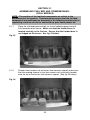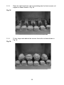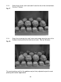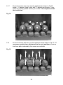
1
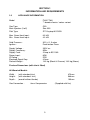
Warwick Powerflue
FUEL EFFECT
POWERFLUE GAS FIRES
Installation, Maintenance & User Instructions
Hand these instructions to the user
Model No. FVNC**MN is for use on Natural Gas (G20) at a supply
pressure of 20 mbar in G.B. / I.E.
** denotes fascia / colour variant
CONTENTS
Section 1
Information and Requirements
1.0
1.1
1.2
1.3
1.4
1.5
1.6
1.7
1.8
Appliance Information
Conditions of Installation
Flue terminal position
Fireplace / surround suitability
Fire place opening / catchment space
Shelf position
Installation types
Hearths
Spillage monitoring system
Section 2
Installation of Fire
2.1
2.2
2.3
2.4
2.5
2.6
2.7
Unpacking the fire
Marking the flue pipe opening
Marking / making the fan unit recess (Inset fan installations)
Marking the fan unit spacer position (Outset fan installations)
Securing the fan box / running the gas supply pipe
Making the electrical connection
Gas tightness and inlet pressure
Section 3
Assembling Fuel Bed and Commissioning
3.1
3.2
3.3
Assembling the ceramics and fuel bed (Coal models)
Lighting the appliance
Checking for clearance of combustion
products
Section 4
Maintenance
4.1
4.2
4.3
4.4
4.5
Removal
Removal
Removal
Removal
Removal
of
of
of
of
of
the Burner Assembly
the Piezo Igniter
the Control Tap
the Thermocouple
the Solenoid
PAGE
3
4
5
6
6
6
7-9
9
9
10
10
11-13
14-16
17-19
20
21
22-26
27
28
29
29-30
30
30
30-31
Spare Parts Shortlist / Wiring Diagram
32
Section 5
User Instructions
5.1
5.2
5.3
5.4
Installation information / about your new fire
Lighting the appliance
Cleaning instructions
Re-assembling the ceramics and fuel-bed
Efficiency Declaration
33-35
35
36
37-41
The efficiency of this appliance has been measured as specified in BS EN 13278 and the
result is 50%. The gross calorific value of the fuel has been used for this efficiency
calculation. The test data from which it has been calculated has been certified by GL
Industrial Services UK Ltd. The efficiency value may be used in the UK Government’s
Standard Assessment Procedure (SAP) for energy rating of dwellings.
This appliance is manufactured by :-
BFM Europe Ltd, Trentham Lakes, Stoke-on-Trent, ST4 4TJ
2
SECTION 1
INFORMATION AND REQUIREMENTS
1.0
APPLIANCE INFORMATION
Model
FVNC**MN
** denotes fascia / colour variant
Gas Type
Main injectors (2 off)
Pilot Type
G20
Size 235
SIT Oxystop NG 9022
Max. Gross Heat Input :
Min. Gross Heat Input :
6.5 kW
4.2 kW
Cold Pressure :
Ignition :
20.0 +/-1.0 mbar
Push-button Piezo
Supply Voltage :
Supply Frequency :
Supply Fuse :
Power Input :
IP Rating :
Electrode Spark Gap
Packed Weight :
230V a.c.
50Hz
3 Amp to BS 1362
60W
IP00
4.0mm
14.5 kg (Black & Chrome) 16.5 kg (Brass)
Fire box Dimensions (with trim’s fitted)
All Warwick Models
Width :
Height :
Depth :
(with standard trim)
(with standard trim)
(overall-without fender)
Gas Connection :
470mm
586mm
155mm
8mm Compression
3
(Supplied with fire)
INSTALLATION REQUIREMENTS
1.1
CONDITIONS OF INSTALLATION
It is the law that all gas appliances are installed only by a GAS SAFE Registered
Installer, in accordance with these installation instructions and the Gas Safety
(Installation and Use) Regulations 1998 as amended. Failure to install appliances
correctly could lead to prosecution. It is in your own interest and that of safety to
comply with the law.
The installation must also be in accordance with all relevant parts of the Local and
National Building Regulations where appropriate, the Building Regulations
(Scotland Consolidation) issued by the Scottish Development Department, and all
applicable requirements of the following British Standard Code of Practice.
1.
2.
3.
4.
5.
6.
7.
B.S. 5871 Part 2 Installation of Inset Fuel Effect Gas Fires
B.S. 6891 Installation of Gas Pipework
B.S. 5440 Parts 1 & 2 Installation of Flues and Ventilation
B.S. 1251 Open fire place components
B.S. 715 Metal flue pipes for gas appliances
B.S. 6461 Part 1 Installation of Chimneys and flues
I.S. 813 : 1996 Domestic Gas Installation (Republic of Ireland)
No purpose made additional ventilation is normally required for this
appliance, when installed in G.B. When Installing in I.E. please consult
document I.S. 813 : 1996 Domestic Gas Installation, which is issued by the
National Standards Authority of Ireland. If installing in Northern Ireland,
please consult local building regulations. Any purpose made ventilation
must be checked periodically to ensure that it is free from obstruction.
4
1.2
FLUE TERMINAL POSITION
The minimum acceptable dimensions from the flue terminal to obstructions and
ventilation openings are shown below in fig. 1 and listed in the table (fig. 2 below)
IT IS IMPORTANT THAT THE POSITION OF THE FLUE ALLOWS THE FREE
PASSAGE OF AIR ACROSS IT AT ALL TIMES.
Fig. 1
Fig. 2
DIMENSION TERMINAL POSITION
A
B
C
D
E
F
G
H
I
J
K
L
M
N
O
P
Q
MINIMUM DIMENSION
Directly below an opening, air brick,
opening window
Above an opening, air brick,
opening window
Horizontally to an opening, air brick,
opening window etc.
Below gutters, soil pipes or drain pipes
Below eaves
Below balconies or car port roof
From a vertical drain pipe or soil pipe
From an internal or external corner
Above ground roof or balcony level
From a surface facing the terminal
From a terminal facing the terminal
From an opening in the car port
Vertically from a terminal on the same wall
Horizontally from a terminal on the
same Wall
From the wall on which the terminal is mounted
From a vertical structure on the roof
Above intersection with roof
5
300mm (12 in.)
300mm (12 in.)
300mm (12 in.)
75mm (3 in.)
200mm (8 in.)
200mm (8 in.)
150mm (6 in.)
200mm (8 in.)
300mm (12 in.)
600mm (24 in.)
1200m (48 in.)
1200m (48 in.)
1500mm (59 in.)
300mm (12 in.)
50mm (2 in.)
N/A
150mm
1.3
FIREPLACE / SURROUND SUITABILITY
The fire must only be installed on a hearth it must not be installed directly onto
carpet or other combustible floor materials. The fire is suitable for fitting to
non-combustible fire place surrounds and proprietary fire place surrounds with a
temperature rating of at least 150oc. If a heating appliance is fitted directly against
a wall without the use of a fire surround or fire place all combustible material must
be removed from behind the trim. Soft wall coverings such as blown vinyl, wall
paper etc. could be affected by the rising hot air and scorching and/or discoloration
may result. Due consideration should be made to this when installing or
decorating.
1.4
FIRE PLACE OPENING
The front opening of the fire place must be between 330 and 430mm wide, and
between 550 and 565mm high. If the opening exceeds these dimensions then a
surround must be constructed from suitable non-combustible material to produce a
correct size opening. Any surround must be suitably sealed to the fire place to
prevent leakage. See below in fig.3
520mm Minimum
Fig. 3
Fire Opening
550mm Minimum
565mm Maximum
1.5
330mm Minimum
Minimum Flat
Sealing Area
610mm Minimum
430mm Maximum
SHELF POSITION
The fire may be fitted below a combustible shelf providing there is a minimum
distance of 200mm above the top of the fire and the shelf does not project more
than 150mm. If the shelf overhangs more than 150mm the distance between the
fire and the shelf must be increased by 15mm for every 25mm of additional
overhang over 150mm.
6
1.6
INSTALLATION TYPES
This fire can be fitted against an outside facing facing flat wall surface or into a
fireplace opening cut into the wall.
When fitting the fire in front of the inner cavity wall, the distance between the
mounting face of the fire and the rear face of the firebox must be a minimum of
155mm, a false chimney breast or fireplace surround should be constructed. The
firebox must then be secured into the fireplace using the method described in
section 2. Any combustible material must be removed from the the area around
the firebox flange. In all installations, ensure that there is no structural damage to
the property or the damp course. See fig. 4 below
Fig. 4
False Chimney
Breast or Fireplace
Rebate
155mm All
Models
Flue Pipe
155mm All
Models
Fan Unit Outset
510mm Maximum with standard flue duct
supplied and with fan unit outset
Flue Pipe
Fan Unit Inset
150mm is minimum 655mm Maximum with standard flue duct
supplied and with fan unit inset
flue length
Up to 5000mm (5 metres) maximum with up to 3 off 90 degree bends with optional extra flue duct
components is available - see spare parts list for part numbers
When fitting the fire into a cavity wall, this requires the opening of the inner leaf
of brickwork, to recess the firebox into. The opening needs to be sufficient to
accomodate the firebox. To support the wall above the hole, a suitable lintel must
be inserted across the top of the opening. If fitting the appliance into a cavity wall,
a lintel 750mm long having a thickness of 75mm with a height of the inner wall
should be used. The lintel could be either pre-cast concrete or steel - Catnic
CN52 or CN 46 could be used, depending upon the inner wall thickness. Before
proceeding with the installation of the fire, an assessment of the area immediately
above the fire is required, see Fig. 5 overpage. If there is no existing openings
within either triangle, proceed with forming the opening. However, if opening or
beams occur within either triangle, then you should seek specialist advice from a
structural engineer or consider relocating the proposed position of the firebox.
7
Fig. 5
The Interactive Zone Openings, beams or joists within
this area need to be assessed.
400mm interactive
area
Load triangle - No beam or
opening permissible within this
area
600mm load
triangle
Lintel
e.g. 750mm x 75mm
Firebox recess in
wall
Opening Height
550mm Minimum
570mm Maximum
Opening Width
50mm Minimum Hearth Thickness
375mm Minimum
440mm Maximum
To proceed with the installation when the above stated criteria have been
satisfied :Mark out where possible, centrally beneath a block joint where the lintel is to be
fitted. Unless lime mortar has been used it will be necessary to drill four holes
with a masonary drill, then use a mechanical cutter such as a “shark saw” to cut
out the correct size of slot in the inner leaf of brickwork for the lintel you have
chosen to install. See fig. 6 below.
Fig. 6
Fit the lintel, ensure that it is bedded on mortar. Do not bed on a dry bed.
Then remove all debris from the cavity and construct the opening to the minimum /
maximum opening sizes as shown overpage (fig. 7) and in section 1.4, (fig. 3)
8
Remove any combustible material from within the area of the opening. No
combustible material can be allowed to come into contact with any area of the
appliance.
Fig. 7
Opening Sizes Width :-
330mm Minimum
430mm Maximum
Opening sizes Height :-
Lintel must project
Minimum of 150mm
each side of the
opening
550mm Minimum
565mm Maximum
1.7
HEARTHS
Ensure that the recess that is cut is to the required
dimensions and is screed level so that the firebox will
sit level within the recess.
This appliance must only be installed on to a concrete or non-combustible hearth.
The hearth material must be a minimum thickness of 12mm with the top surface at
least 50mm above the floor. The hearth must be fitted symmetrically about the fire
opening and have a minimum width of 760mm and a minimum projection of
300mm forwards from the fire opening.
1.8
SPILLAGE MONITORING SYSTEM
This appliance is fitted with an atmosphere sensing spillage monitoring system in
the form of an oxygen sensing burner. This is designed to shut the fire off in the
event of a partial or complete blockage of the flue causing a build up of
combustion products in the room in which the fire is operated. The following are
important warnings relating to this spillage monitoring system :1) The spillage monitoring system must not be adjusted by the installer.
2) The spillage monitoring system must not be put out of operation.
3) When the spillage monitoring system is exchanged only a complete original
manufacturers part may be fitted.
9
2.1
SECTION 2
INSTALLATION OF FIRE
UNPACKING THE FIRE
Carefully lift the fire out of the carton. Remove the loose item packaging carefully
from the front of the appliance. Check the contents as listed :Packing Check List - All Models
1 off
1 off
1
1
1
1
1
off
off
off
off
off
1 off
2.2
Fire box / burner assembly & standard flue duct
Boxed fuelbed base, 2 piece ceramic front rail and 11 synthetic coals or
pebbles
Loose items bag
Fret / Ashpan cover
Trim
Installation, maintenance & user instruction book
Rope seal, fan box clamping plate, fan spigot & fixing screws (packed in
loose items)
Boxed fan unit (Pack 2 of 2)
MARKING THE FLUE PIPE OPENING ON THE WALL (ALL MODELS)
Drill a pilot hole into the outer leaf of brickwork at a height of 482mm from the
hearth level, centrally about the firebox, then create a square hole 100mm / 4 inch
vertically central to the centre line of the appliance. See fig. 8 below.
NOTE : If the fire is to be fitted against the inner cavity wall, the inner and
outer cavity walls will require the 100mm / 4 inch hole creating
Fig. 8
IMPORTANT NOTE :
DO NOT FIT THIS APPLIANCE FAN UNIT ABOVE A HEIGHT OF
1.4M FROM GROUND LEVEL
MAXIMUM
1.4 METRE
100mm / 4 inch
square hole
480mm to Centre
of Flue Pipe from
bottom of opening
Inner
Cavity Wall
Outer
Cavity Wall
10
2.3
MARKING / MAKING THE FAN UNIT RECESS ON THE OUTER
WALL (WHEN INSET FAN UNIT INSTALLATION IS REQUIRED).
2.3.1
Cut the opening for the fan unit and the flue pipe duct in the outer wall
as shown below in Fig. 9.
Fig. 9
Centre Point of
Flue Duct
125mm
300mm
630mm
480mm
65mm
Hearth Level
2.3.2
Fig. 10
2.3.3
To proceed with the installation, take the flue pipe (400mm in length)
and secure to the firebox as shown below in Fig. 10, with the 4 off fixing
screws supplied.
Carefully place the firebox and flue pipe together into the builders
opening and allow the flue pipe to protrude through the hole in the outer
cavity wall.
11
2.3.4
Mark the flue pipe in line with the outer wall surface.
NOTE :- When cutting the flue pipe to length, allowance for the rebate
on the fire surround used or false chimney breast constructed must be
taken into account, if the surround or false chimney breast is not
already in place.
2.3.5
Subtract 145mm from the cut line as marked in section 2.3.4, to account
for the recessed fan unit, then cut the flue pipe. Secure the firebox /
and run the gas supply into the firebox as detailed in section 2.5
2.3.6
The electrical connection should be completed to the mains supply via a
3 amp fused switched spur or 3 pin socket and 3 amp plug. DO NOT
MAKE THE FINAL ELECTRICAL CONNECTION AT THIS POINT. The
product is supplied with 2.5 metres of three core mains cable, this cable
should be routed as inconspicuously as possible, i.e. chased into the
plaster.
2.3.7
Route the five core cable that runs from the firebox to the fan unit within
the opening, ensure that it is not trapped or coming into contact with the
firebox. Position the molex connector through the opening in the outer
wall, for connection to the fan chassis later in the installation.
2.3.8
Remove the fan box cover as shown below in Fig. 11 via the three
screws.
Fig. 11
2.3.9
Remove the 2 off lower self tapping screws and loosen the 2 off pan
head screws that hold the fan chassis in position and then lift the fan
chassis and gasket clear and store in a safe position.
12
2.3.10
Fit the flue spigot to the fan box as shown below in Fig. 12 with 3 off
screws supplied in the loose items pack.
Fig. 12
2.3.11
Fit the 5 core cable through the grommet (slit the grommet) in the fan
box cover. Insert the fan box into the opening as cut in section 2.3.1,
Fig. 9
2.3.12
Fix the fan box to the outer skin of brickwork by using the 3 off bolts to
secure it. Ensure it is fitted centrally around the flue pipe opening.
2.3.13
Fit the fibre glass rope seal as supplied in the loose items pack into the
gap between the flue pipe and ensure it is flush with the edge of the flue
pipe.
2.3.14
Secure the cable gland to it’s bracket on the fan carrier and then
connect the fan power cable via the molex connector block to the fan
chassis, (see section 2.6, Fig. 22)
2.3.15
Replace the fan chassis and it’s gasket into the fan unit in reverse order
to section 2.3.9
2.3.16
Replace the fan cover via the three screws in reverse order to section
2.3.8 / Fig. 11.
2.3.17
Run a bead of mastic around the fan box between the fan and the wall
to prevent water ingress.
13
2.4
MARKING THE FAN UNIT SPACER POSITION ON THE OUTER
WALL (WHEN OUTSET FAN UNIT INSTALLATION IS SPECIFIED).
2.4.1
Cut the opening for the fan flue duct in the outer wall as shown below in
Fig. 13.
Fig. 13
Centre Point of
Flue Duct
100mm
482mm
65mm
100mm
Hearth Level
2.4.2
To proceed with the installation, take the flue pipe (400mm in length)
and secure to the firebox as shown below in Fig. 14, with the 4 off fixing
screws supplied.
Fig. 14
14
2.4.3
Mark the flue pipe in line with the outer wall surface so that it can be cut
to length.
NOTE :- When cutting the flue pipe to length, allowance for the rebate
on the fire surround used or false chimney breast constructed must be
taken into account.
2.4.4
Cut the flue to length, as marked in section 2.3.3. Secure the firebox
and run the gas supply into the firebox as detailed in section 2.5.
2.4.5
The electrical connection should be completed to the mains supply via a
3 amp fused switched spur or 3 pin socket and 3 amp plug. DO NOT
MAKE THE FINAL ELECTRICAL CONNECTION AT THIS POINT. The
product is supplied with 2.5 metres of three core mains cable, this cable
should be routed as inconspicuously as possible, i.e. chased into the
plaster.
2.4.6
Route the five core cable that runs from the firebox to the fan unit within
the opening, ensure that it is not trapped or coming into contact with the
firebox. Position the molex connector through the opening in the outer
wall, for connection to the fan chassis later in the installation.
2.4.7
Remove the fan box cover as shown below in Fig. 15 via the three
screws.
Fig. 15
2.4.8
Remove the 2 off lower self tapping screws and loosen the 2 off pan
head screws that hold the fan chassis in position and then lift the fan
chassis and gasket clear and store in a safe position.
15
2.4.9
Remove the 2 off lower self tapping screws and loosen the 2 off pan
head that hold the fan chassis in position and then lift the fan chassis
and gasket clear and store in a safe position.
2.4.10
Fit the flue spigot to the fan box as shown below in Fig. 16 with 3 off
screws supplied in the loose items pack.
Fig. 16
2.4.11
Fit the 5 core cable through the grommet (slit the grommet) in the fan
box cover.
2.4.12
Fix the fan box to the outer skin of brickwork by using the 3 off bolts to
secure it. Ensure it is fitted centrally around the flue pipe opening.
2.4.13
Fit the fibre glass rope seal as supplied in the loose items pack into the
gap between the flue pipe and ensure it is flush with the edge of the flue
pipe.
2.4.14
Secure the cable gland to it’s bracket on the fan carrier and then
connect the fan power cable via the molex connector block to the fan
chassis (see section 2.6, Fig. 22)
2.4.15
Replace the fan chassis and it’s gasket into the fan unit in reverse order
to section 2.4.8.
2.4.16
Replace the fan cover via the three screws in reverse order to section
2.4.7.
2.4.17
Run a bead of mastic around the fan box between the fan and the wall
to prevent water ingress.
16
2.5
SECURING THE FIREBOX IN THE FIREPLACE OPENING /
RUNNING THE GAS SUPPLY PIPE.
2.5.1
Mark out and drill 4 off No 14 (6mm) holes in the back face of the fire
opening (inner face of the outer cavity wall in most instances) in the
positions shown below in fig. 17
Fig. 17
325mm
100mm
500mm
Fireplace Opening
20mm
2.5.2
Fit the wallplugs provided and screw the fixing eyes securely into the
rear of the fire opening. If the clearance at the rear of the fire is at the
minimum specified for a powerflue application, it may be necessary to
bend over the lower fixing eyes after screwing them fully in to the rear
of the outer cavity wall inner face.
2.5.3
Run the gas supply in from the right hand side of the firebox as shown
below in Fig. 18
Fan Unit
Fig. 18
Gas Supply
Firebox
Flue Pipe
Approx.
60mm
2.5.4
Fireplace
Continue with the fan unit installation as detailed in section 2.3.6
(Inset fan installation) or section 2.4.5 (Outset fan installation)
17
Proceed as follows to remove the burner assembly from the firebox :2.5.5
Remove the burner heat shield from the front of the fire box to allow
access to the burner, as shown below in fig. 19
Fig. 19
2.5.6
Fig. 20
Break the connection between the pressure test point elbow and the
solenoid block. Remove the four retaining screws securing the burner
to the firebox. The base of the burner unit can now be pulled
forward, allowing the burner to be removed from the fire box.
See fig. 20 below.
2.5.7
Uncoil the two fire fixing cables and thread one end of each of the
cables through one of the two holes on each side of the flue outlet
shroud.
2.5.8
Position the fire carefully on the (protected) surface of the hearth and
reach into the fire opening. Thread each of the cables vertically
downwards through the pair of fixing eyes on the same side of the fire.
Thread the free end of the cables through the corresponding circular
hole on each side of the lower rear of the fire. Carefully slide the fire
box back into the fire opening and pull both cables tight.
18
2.5.9
Thread a tensioning screw over each of the cables and ensure that the
tensioning nut is screwed fully up against the hexagon shoulder of the
tensioning screw (this provides maximum travel for the tensioning nut).
2.5.10
Fit a screwed nipple on to each of the cables and pull hand tight up
against the tensioning screw, then secure each nipple with a flat
bladed screwdriver. See fig. 21 below.
Fig. 21
2.5.11
Evenly tighten the tensioning nuts to tension both cables and pull the
fire snugly against the wall. Do not overtighten, it is only necessary to
pull the seal up against the sealing face of the wall, it does not need to
be compressed. Check that there are no gaps behind the seal.
2.5.12
With the fire securely in place, if a concealed gas connection has been
made through the access holes in the R/H side of the fire, the hole
should be closed around the pipe to prevent leakage of air
through the gap around the pipe.
2.5.13
Situate the isolation valve, supplied in the loose items pack at a
convenient point in the installation.
2.5.14
Refit the burner. Fit the four retaining screws and check that the burner
is correctly locked into position. Before making the final gas connection
to the solenoid valve, thoroughly purge the gas supply pipework to
remove all foreign matter, otherwise serious damage may be caused to
the gas control valve on the fire.
NOTE :- Failure to correctly purge the pipework will invalidate the
guarantee
19
2.6
MAKING THE ELECTRICAL CONNECTION.
WARNING : THIS APPLIANCE MUST BE EARTHED AND SHOULD BE
PREFERABLY CONNECTED VIA A 3 AMP FIXED FUSED
SPUR WITH A MINIMUM CONTACT SEPARATION OF 3MM.
IT MAY HOWEVER BE CONNECTED TO A 3 PIN PLUG TO
BS 5733, THAT IS FITTED WITH A 3 AMP FUSE TO BS
1362.
2.6.1
Remove the painted fan box cover, secured with 3 off screws as shown
in fig 15, page 15.
Fig. 22
Connect the 2 off
terminal
connectors
together as
shown
2.6.2
Connect the 2 off 6 way molex connectors to the fan power cable
emerging from the electronic circuit board, as shown below in Fig. 22
2.6.3
Replace the fan box cover and secure with 3 off screws as shown in
fig. 15 on page 15.
2.6.4
Make the final electrical connection to the 3 amp fixed fused spur
(preferred method) or 3 pin plug.
2.6.5
Proceed to commission the appliance as detailed in section 2.7 to 3.4.
20
2.7
GAS TIGHTNESS AND INLET PRESSURE
2.7.1
Remove the pressure test point screw from the inlet elbow and fit a
manometer.
2.7.2
Turn on the main gas supply and carry out a gas tightness test.
2.7.3
Depress the “ON / OFF” switch on the switch control panel,
located at the right hand side of the fire (when viewed from the front) to
the “ON” position. Press the momentary switch, the fan unit will
operate, and when the air pressure switch (located inside the fan unit)
detects sufficient air flow within the flue, an audible click will be heard
and the gas solenoid valve will open.
2.7.4
Continue to hold-in the control knob and press the igniter button. If the
burner does not light, continue to press the igniter button until ignition
occurs. Continue to hold the control knob for a minimum of 10 seconds
to allow the thermocouple to heat up, if the burner goes out when the
control knob is released, repeat the lighting sequence.
2.7.5
Check that the gas pressure is 20.0 mbar (+/- 1.0mbar) 8.0 in w.g.(+/0.4 in w.g.).
2.7.6
After removing the manometer, ensure that the pressure test point
screw is checked for gas tightness with suitable leak detection
spray or fluid.
21
SECTION 3.1
ASSEMBLING FUEL BED AND COMMISSIONING (COAL MODELS)
NOTE : The position of the fuel-bed components are critical to the
performance of the product. Therefore please ensure that the fuel-bed
components are positioned as described in the following section prior to
requesting a service call due to soot build up, poor flame pattern etc.
3.1.1
Fig. 23
3.1.2
Place the fuel-bed base centrally on to the fuelbed support and pull
fully forwards to the burner. Make sure that the fuelbed base is
located centrally in the fire box. Ensure that the fuelbed base is
not lodged on the burner. See fig. 23 below.
Position front ceramic rail on burner front ceramic support and ensure
that the locating channel in the front ceramic rail is correctly located
onto the lip on the burner front ceramic support. (See fig. 24 below)
Fig. 24
22
3.1.3
Place the right hand front coal rail moulding onto the front ceramic rail
support as shown below in Fig. 25
Fig. 25
3.1.4
Fig. 26
Fit four large coals behind the ceramic front rails as shown below in
Fig. 26
23
3.1.5
Fig. 27
3.1.6
Fig. 28
Select three of the small coals and fit onto the ribs of the fuel-bed base.
See fig. 27 below
Select the remaining four small coals and arrange along the rear of the
fuelbed, directly behind the third row of coals. See fig. 28 below.
The exact position and fit of the pebbles may be finely adjusted to give the most
pleasing and random appearance.
24
3.1.7
Ensure the coals sizes are correctly positioned as shown in Fig 29
below. “L” denotes “large” coals and “S” denotes small coals. If any
coals are missing, please contact your retailer. Do not proceed with
the installation.
Fig. 29
S
L
3.18
S
S
S
S
L
L
S
S
L
Ensure the flame paths are un-interrupted as shown below in Fig. 30. If
necessary, make minor adjustments to the coal positions to ensure
the flame paths indicated by the arrows are available.
Fig. 30
25
The exact position and fit of the coals may be finely adjusted to give the most
pleasing and random appearance.
Warning : Use only the coals supplied with the fire. When replacing the
coals remove the old coals and discard them. Fit a complete set of
coals of the correct type. Do not fit additional coals or any coals
other than a genuine replacement set.
To ensure that the release of fibres from these R.C.F (Refractory Ceramic
Fibre) articles is kept to a minimum, during installation and servicing we
recommend that you use a HEPA filtered vacuum to remove any dust
accumulated in and around the appliance before and after working on the
appliance. When replacing these articles we recommend that the replaced
items are not broken up, but are sealed within heavy duty polythene bags,
clearly labelled as “RCF waste”. RCF waste is classed as a “stable”, non
reactive hazardous waste and may be disposed of at a landfill licensed to
accept such waste Protective clothing is not required when handling these
articles, but we recommend you follow the normal hygiene rules of not
smoking, eating or drinking in the work area, and always wash your hands
before eating or drinking.
This appliance does not contain any component manufactured from
asbestos or asbestos related products.
FITTING OF THE TRIM / FRET
The trim is secured onto the firebox flange by the use of magnets. The fret, should
be placed upto the fire with the ashpan and centralised.
26
3.2
LIGHTING THE APPLIANCE (ALL MODELS)
3.2.1
Turn on the gas isolation tap.
3.2.2
Depress the “ON / OFF” switch on the switch control panel,
located at the right hand side of the fire (when viewed from the front) to
the “ON” position. Press the momentary switch, the fan unit will
operate, and when the air pressure switch (located inside the fan unit)
detects sufficient air flow within the flue, an audible click will be heard
and the gas solenoid valve will open.
3.2.3
Depress the control knob and turn anti-clockwise to the position
marked ignition / low rate. Hold in the control knob for a few seconds to
purge the pipe work.
3.2.4
Continue to hold-in the control knob and press the igniter button. If the
burner does not light, continue to press the igniter button until ignition
occurs. Continue to hold the control knob for a minimum of 10 seconds
to allow the thermocouple to heat up, if the burner goes out when the
control knob is released, repeat the lighting sequence.
3.2.5
Turn the control knob in the anti-clockwise direction to the high position
and the gas rate will increase to high rate (6.5kW)
3.2.6
Turn the control knob clockwise to the low position and the gas input
will be reduced to the minimum setting (4.2kW)
3.2.7
Slightly depress the control knob and turn to the off position, the burner
will now be extinguished.
WARNING : If the fire goes out for any reason or is turned off and it
is necessary to re-light the fire it is important to allow the
fire to cool for 3 minutes before attempting to re-light it.
27
3.3
CHECKING FOR CLEARANCE OF COMBUSTION PRODUCTS (ALL
MODELS)
3.3.1
Close all doors and windows in the room.
3.3.2
Light the fire and allow to run for approximately 5 minutes on high
position.
3.3.3
After approximately 5 minutes hold a smoke match just inside and
below the centre of the lower front edge of the top of the fire. (It is
recommended that a suitable smoke match holder is used when check
ing for clearance of combustion products). All smoke generated should
be drawn back into the flue. If slight spillage occurs or if in doubt,
repeat the test after a further 5-10 minutes.
If the test indicates that spillage is occurring, check that the
supply voltage to the appliance is 230V (+/- 5%). If the supply
voltage is outside these parameters, this could be causing the
appliance to spill. Obtain the correct supply voltage and re-test
the appliance from cold.
3.3.4
If spillage persists, the fan unit is not functioning correctly and a fault
exists. If, after investigation the fault cannot be traced and rectified, the
fire must be disconnected from the gas supply and expert advice
obtained from the manufacturer.
3.3.5
If there is an extractor fan fitted any where in the vicinity of the
appliance, the spillage test should be repeated with the fan running on
maximum and all interconnecting doors open.
3.3.6
After ensuring that the fire is safe to use it should be left on high
position to fully warm up. During this time a slight odour may be
noticed, this is due to the “newness” of the fire and will soon disappear.
At this stage any minor adjustments to the coals should be made using
suitable long handled tongs and taking care not to damage the coals.
Finally, hand the Installation and Maintenance Instructions and the
Users Instructions over to the customer and explain the operation of the
fire.
28
SECTION 4
MAINTENANCE
Servicing Notes
Servicing should be carried out annually by a competent person such as a GAS
SAFE registered engineer and must include an oxypilot change. This is a
condition of the Flavel guarantee schemes.
The service should include visually checking the chimney and fire opening for
accumulations of debris and a smoke test to check for a positive up-draught in the
chimney.
The condition of the coals or pebbles should be checked and if necessary the
whole set should be replaced with a genuine replacement set.
The burner assembly is designed to be removed as a complete unit for ease of
access. After any servicing work a gas tightness check must always be
carried out. All sections apply for both coal and pebble fuelbed variants.
For Diagrams refer to Section 2
4.1
Removing the burner assembly from the fire.
4.1.1
Prepare work area (lay down dust sheets etc.)
4.1.2
Lift the trim and ash pan cover / fret out of the way and put
them in a safe location. Remove the loose pebbles or coals from the
fuel bed. Remove the front ceramic from the rail. Unscrew
the two pozi-driv fixing screws which secure the burner heat shield and
remove it from the fire.
4.1.3
Isolate the gas supply. Remove the inlet pipe from the appliance
pressure test point elbow Unscrew and remove the four
screws which retain the burner. Remove the burner assembly from the
fire. Disconnect the two leads from the on / off switch.
4.1.4
To refit the burner assembly. Push the base of the control panel fully
into the fire and secure with the four screws. Refit the gas supply pipe
and carry out a gas tightness test. Refit the burner heat shield then
refit the fuelbed referring to section 3.1 / 3.2 for the correct layout. The
trim and fret / ash pan cover can now be re-positioned.
4.2
Removing the Piezo Igniter (All models).
4.2.1
Isolate the appliance from the gas and electricity supply.
4.2.2
Remove the burner assembly as in section 4.1
4.2.3
Disconnect the ignition lead from the piezo and unscrew the
retaining nut on the rear of the control panel. Withdraw the piezo from
the front of the control panel. Re-assemble in reverse order and carry
29
out a gas tightness test. Ensure the heatshield is re-fitted.
4.3
Removing the Control Tap from the fire.
4.3.1
Remove the burner assembly as in section 4.1.
4.3.2
Pull the control knob off the control tap spindle.
4.3.3
Loosen and remove the three gas pipe retaining nuts from the control
tap and release the ends of the gas pipes from the control tap body.
Loosen and remove the thermocouple securing nut from the end of the
control tap.
4.3.4
Unscrew the control tap locknut from the front of the control panel and
remove the control tap.
4.3.5
To refit a control tap, reassemble in reverse order noting that the control
tap locates with a flat in the control panel. Carry out a gas tightness
test after re-assembly.
4.4
Removing the Oxy-Pilot Assembly
Note : Because this appliance is fitted with an atmosphere sensing ‘OxyPilot’ it is not possible to replace the thermocouple separately, because the
thermocouple position is factory set to a tight tolerance. Any replacement of
parts on the pilot requires a complete new pilot assembly.
4.4.1
Remove the burner assembly as in section 4.1
4.4.2
Unscrew and remove the thermocouple retaining nut from the end of the
control tap and disconnect the ignition lead from the pilot electrode.
4.4.3
Unscrew and remove the two pozi-driv screws which secure the pilot
assembly to the burner. Remove the pilot.
4.4.4
Re-assemble in reverse order and carry out a gas tightness test.
4.5
Removing the Solenoid Valve (All models).
4.5.1
Isolate the appliance from the gas and electricity supply.
4.5.2
Remove the burner assembly as described in section 4.1
4.5.3
Disconnect the solenoid plug from the harness.
4.5.4
Unscrew the solenoid pipe from the retaining brackets.
30
4.5.5
Remove solenoid from pipe and refit new solenoid.
PARTS SHORTLIST / WIRING DIAGRAM (FIG. 37)
Replacement of any other parts must be carried out by a competent person such
as a GAS SAFE registered gas installer. The part numbers of the main
replaceable parts are as follows, these are available from your local stockist,
whose details may be found on the BFM Europe website, address as shown
on the rear cover.
Coal fuelbed base
Coal fuelbed front rails (pair)
Replacement coal set
Complete pebble ceramic set (base, front rails and pebbles)
Pebble fuelbed base
Pebble fuelbed front rail L/H
Pebble fuelbed front rail R/H
Replacement pebble set
Manual Gas Valve
Piezo Igniter
Ignition Wire
Pressure Switch
Solenoid Valve
Fan Motor
Fan Proving Unit
2.5 metre standard wiring loom
6.0 meter wiring loom (for use with additional flue duct)
830mm flue length (for use with additional flue duct)
100mm x 100mm duct connector (for use with additional flue duct)
100mm x 100mm 45 degree bend (for use with additional flue duct)
100mm x 100mm 90 degree bend (for use with additional flue duct)
Fig. 37
B-96400
B-96410
B-96420
B-107340
B-107350
B-107360
B-107370
B-107380
B-102880
B-1320
B-14340
CV-103507
CV-104303
CV-103330
CV-103505
CV-H47
CV-H79
CV-3350
CV-3351
CV-3359
CV-3357
Important Note : Should the electric mains supply cable require replacing,
this must only be carried out by a BFM service agent or other suitably
qualified person.
31
SECTION 5
USER INSTRUCTIONS
5.1 INSTALLATION INFORMATION
5.1.1 CONDITIONS OF INSTALLATION
It is the law that all gas appliances are installed in accordance with the rules in
force only by a competent (e.g. GAS SAFE Registered) Installer in G.B, and in
accordance with the installation instructions and the Gas Safety (Installation and
Use) Regulations 1998. Failure to install appliances correctly could lead to
prosecution. It is in your own interest and that of safety to comply with the law.
The fire may be fitted below a combustible shelf provided that the shelf is at least
200mm above the top of the appliance and the depth of the shelf does not exceed
150mm.
The fire may be installed below combustible shelves which exceed 150mm deep
providing that the clearance above the fire is increased by 15mm for each 25mm
of additional overhang in excess of 150mm.
No purpose made additional ventilation is normally required for this
appliance when installed in G.B. When installed I.E. please consult
document I.S. 813 : 1996 Domestic Gas Installation which is issued by the
National Standards Authority of Ireland. Any purpose made ventilation
should be checked periodically to ensure that it is free from obstruction.
If this appliance is fitted directly on to a wall without the use of a fireplace or
surround, soft wall coverings such as wallpaper, blown vinyl etc. could be affected
by the heat and hot air and may discolour or scorch. This should be considered
when installing or decorating.
The Model number of this appliance is as stated on the rating plate affixed to the
control panel of the fire and the appliance is manufactured by:BFM Europe Ltd
Trentham Lakes
Stoke on Trent
ST4 4TJ
32
5.1.2 ABOUT YOUR NEW WARWICK COAL GAS FIRE
The Flavel Warwick coal effect gas fire incorporates a unique and highly
developed fuel bed which gives the realism of a loose coal layout combined with
realistic flames and glow. The use of durable ceramic material in the
construction of the fuelbed components ensures long and trouble free operation.
Please take the time to fully read these instructions as you will then be able to
obtain the most effective and safe operation of your fire.
When first using the new fire a slight smell may be noticed. This is due to starch
used in the manufacture of the soft ceramic coals, it is non-toxic and will soon
disappear.
Please take the time to fully read these instructions as you will then be able to
obtain the most effective and safe operation of your fire.
5.1.3
IMPORTANT SAFETY INFORMATION
WARNING
This appliance has a naked flame and as with all heating appliances a
fireguard should be used for the protection of children, the elderly and
infirm. Fireguards should conform to B.S. 8423 : 2002 should be fitted.
(Fireguards for use with gas heating appliances).
It is important that this appliance is serviced at least once a year by a GAS SAFE
registered gas installer ( in G.B.) and that during the service the fire is removed
from the fire opening and the flue pipe visually checked for debris or blockages
which must be removed. We recommend that during the annual service,
replacement of the Oxypilot is carried out. These are conditions of the
manufacturers guarantee. After installation or during servicing a spillage
test must always be carried out.
Rubbish of any type must NEVER be thrown onto the fuel-bed, this could affect
safe operation and damage the fire.
Any debris or deposits should be removed from the fuel-bed from time to time.
This may be carried out by referring to the cleaning section as described later in
this book.
Only the correct number and type of coals must be used and only
complete and genuine replacement sets can be sourced from BFM Europe Ltd.
Always keep furniture and combustible materials well clear of the fire and never
dry clothing or items either on or near to the fire. Never use aerosols or
flammable cleaning products near to the fire when it is in use.
33
The ceramic fuel-bed remains hot for a considerable period after use and
sufficient time should be allowed for the fire to cool before cleaning etc.
This appliance is not intended for use by persons (including children) with
reduced physical, sensory or mental capabilities, or lack of experience and
knowledge, unless they have been given supervision or instruction
concerning use of the appliance by a person responsible for their safety.
Children should be supervised to ensure that they do not play with the
appliance.
5.1.4
SPILLAGE MONITORING SYSTEM
This appliance is fitted with a spillage monitoring system which shuts down the fire
if the evacuation of combustion products from the fire is affected by a partially or
fully blocked flue pipe. If this system operates the fire will go out. If this occurs,
leave the fire for at least three minutes then follow the lighting procedure as
described in the previous section. In the event of repeated operation a GAS
SAFE registered gas installer must be called to investigate and rectify the
cause.
34
5.2
LIGHTING THE APPLIANCE (ALL MODELS)
5.2.1
Turn on the gas isolation tap.
5.2.2
Depress the “ON / OFF” switch on the switch control panel,
located at the right hand side of the fire (when viewed from the front) to
the “ON” position. Press the momentary switch, the fan unit will
operate, and when the air pressure switch (located inside the fan unit)
detects sufficient air flow within the flue, an audible click will be heard
and the gas solenoid valve will open.
5.2.3
Depress the control knob and turn anti-clockwise to the position
marked ignition / low rate. Hold in the control knob for a few seconds to
purge the pipe work.
5.2.4
Continue to hold-in the control knob and press the igniter button. If the
burner does not light, continue to press the igniter button until ignition
occurs. Continue to hold the control knob for a minimum of 10 seconds
to allow the thermocouple to heat up, if the burner goes out when the
control knob is released, repeat the lighting sequence.
5.2.5
Turn the control knob in the anti-clockwise direction to the high position
and the gas rate will increase to high rate (6.5kW)
5.2.6
Turn the control knob clockwise to the low position and the gas input
will be reduced to the minimum setting (4.2kW)
5.2.7
Slightly depress the control knob and turn to the off position, the burner
will now be extinguished.
WARNING : If the fire goes out for any reason or is turned off and it
is necessary to re-light the fire it is important to allow the
fire to cool for 3 minutes before attempting to re-light it.
35
5.3 CLEANING - WARNING
Before attempting any cleaning operation ensure that the fire has been allowed to
fully cool. The trims are easily replaced by re-positioning them on the fire and
pushing it back onto the magnets. Black painted metal parts should be gently
cleaned with a damp cloth.
5.3.1
CLEANING THE BRASS AND PAINTED METAL PARTS
Dependent upon the trim option chosen for use with this fire, there is a variety of
methods that can be chosen to clean the trim. If a Brass trim was supplied with
this fire this is plated brass and this trim must only be cleaned using a clean damp
cloth. Metal polishes must not be used on these trims. If a stainless steel trim
was supplied, then these should only be cleaned using a clean, damp cloth also.
The trim is best cleaned by removing it from the fire and placing it face up on a flat
surface. The trim is easily replaced by repositioning it on the fire and pushing it
back onto the magnets.
Abrasive cleaners, chemical cleaning agents or any type of polish must
never be used as damage to the finish may result.
5.32
CLEANING THE FUEL-BED
We do not recommend cleaning of the pebbles / coals or fuelbed components as
these are fragile and damage may result.
None of these parts must be washed or exposed to any cleaning agents or
water.
Any damaged parts must be replaced by contacting your dealer or telephoning
BFM Europe Ltd. on the number stated on the rear cover of this book. The
coals must only be replaced with a complete and genuine replacement set and the
fire must never be run with the wrong number or damaged coals. The fuel-bed
must be carefully re-assembled as stated in the following sections
36
5.4
RE-ASSEMBLING THE CERAMICS AND FUEL BED
(COAL MODELS)
NOTE : The position of the fuel-bed components are critical to the
performance of the product. Therefore please ensure that the fuel-bed
components are positioned as described in the following section prior to
requesting a service call due to soot build up, poor flame pattern etc.
5.4.1
Fig. 1
5.4.2
Place the fuel-bed base centrally on to the fuelbed support and pull
fully forwards to the burner. Make sure that the fuelbed base is
located centrally in the fire box. Ensure that the fuelbed base is
not lodged on the burner. See fig. 1 below.
Position front ceramic rail on burner front ceramic support and ensure
that the locating channel in the front ceramic rail is correctly located
onto the lip on the burner front ceramic support. (See fig. 2 below)
Fig. 2
37
5.4.3
Place the right hand front coal rail moulding onto the front ceramic rail
support as shown below in Fig. 3
Fig. 3
5.4.4
Fig. 4
Fit four large coals behind the ceramic front rails as shown below in
Fig. 4
38
5.4.5
Fig. 5
5.4.6
Fig. 6
Select three of the small coals and fit onto the ribs of the fuel-bed base.
See fig. 5 below
Select the remaining four small coals and arrange along the rear of the
fuelbed, directly behind the third row of coals. See fig. 6 below.
39
5.4.7
Ensure the coals sizes are correctly positioned as shown in Fig 7
below. “L” denotes “large” coals and “S” denotes small coals. If any
coals are missing, please contact your retailer. Do not proceed with
the installation.
Fig. 7
S
L
5.4.8
S
S
S
S
L
L
S
S
L
Ensure the flame paths are un-interrupted as shown below in Fig. 8. If
necessary, make minor adjustments to the coal positions to ensure
the flame paths indicated by the arrows are available.
Fig. 8
40
The exact position and fit of the coals may be finely adjusted to give the most
pleasing and random appearance.
Warning : Use only the coals supplied with the fire. When replacing the
coals remove the old coals and discard them. Fit a complete set of
coals of the correct type. Do not fit additional coals or any coals
other than a genuine replacement set.
To ensure that the release of fibres from these R.C.F (Refractory Ceramic
Fibre) articles is kept to a minimum, during installation and servicing we
recommend that you use a HEPA filtered vacuum to remove any dust
accumulated in and around the appliance before and after working on the
appliance. When replacing these articles we recommend that the replaced
items are not broken up, but are sealed within heavy duty polythene bags,
clearly labelled as “RCF waste”. RCF waste is classed as a “stable”, non
reactive hazardous waste and may be disposed of at a landfill licensed to
accept such waste Protective clothing is not required when handling these
articles, but we recommend you follow the normal hygiene rules of not
smoking, eating or drinking in the work area, and always wash your hands
before eating or drinking.
This appliance does not contain any component manufactured from
asbestos or asbestos related products.
REMOVAL / RE-FITTING OF THE TRIM / FRET
The trim is secured onto the firebox flange by the use of magnets. The fret, should
be placed upto the fire with the ashpan and centralised.
41
USER REPLACEABLE PARTS
The only user replaceable parts on this fire are the fuelbed components and
pebbles which may be replaced as described in the above section. Replacement
of any other parts must be carried out by a competent person such as a GAS
SAFE registered gas installer. The part numbers of the user replaceable parts are
asfollows, these are available from your local stockist, whose details may be found
on the BFM Europe website, address as shown on the rear cover.
Coal fuelbed base
Coal fuelbed front rails (pair)
Replacement coal set
B-96400
B-96410
B-96420
Important Note : Should the electric mains supply cable require replacing,
this must only be carried out by a BFM service agent or other suitably
qualified person.
Due to our policy of continual improvement and development the exact
accuracy of illustrations and descriptions contained in this book cannot be
guaranteed
Part No. B-133160
Issue 3
BFM Europe Ltd.
Trentham Lakes
Stoke-on-Trent
Staffordshire
ST4 4TJ
www.bfm-europe.com
Telephone - General Enquiries :
Telephone - Service :
(01782) 339000
(0844) 7700169