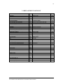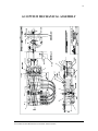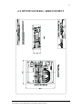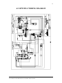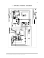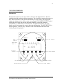
1
Optimal Series
Automatic Transfer Switch
Installation and User Manual for the
OPT2225 Automatic Transfer Switch
Full Version
File: OPT2225 Rev2.5.doc
November, 2004
2
Thank You For Purchasing This DynaGen Product
Please Read Manual Before Installing Unit
Receipt of Shipment and Warranty Return Information
Upon receipt of shipment, carefully remove the unit from the shipping container and
thoroughly examine the unit for shipping damage. In case of damage, immediately
contact the carrier and request that an inspection report be filed prior to contacting
DynaGen.
All returned items are to be shipped prepaid and include a Return Material Authorization
(RMA) number issued by DynaGen. RMA forms are available by contacting DynaGen
Technical Support through the contact methods listed below.
Limited Warranty
DynaGen will repair or replace any Optimal Transfer Switch which proves to be
defective under normal and proper use within Three Years from the date of shipment.
This constitutes the only warranty and no other warranty shall be implied.
We welcome your comments and suggestions. Please contact us at:
DynaGen Technologies Inc.
Phone: 1-888-396-2436
(902) 562 0133
Fax: (902) 567 0633
Email: [email protected]
WEB SITE: www.dynagen.ca
User manual for the OPT2225 Series Automatic Transfer Switch
3
Table of Contents
1: GENERAL DESCRIPTION
1:1 Switchgear
1:1:1 Specification
1:1:2 Operation
1:2 Relay Control Module
1:2:1 Sensing
Adjustment Procedure
1:2:2 System Operation
4
4
4
5
6
6
6
7
2: INSTALLATION INFORMATION
2:1 General
2:2 Recommended Upstream Protection:
2:3 Open Type transfer Switches:
2:4 Remote start switch option:
7
7
7
8
9
3: REPLACING PARTS
3:1 Replacement Parts List
3:1 Main Switch Removal and Replacement
3:2 Motor Removal and Replacement
9
10
11
12
4: MANUAL TRANSFER OF MECHANISM
13
5: RECOMMENDED MAINTENANCE
13
6: DRAWINGS
6:1 Mechanical Assembly
6:2 General Arrangement
6:3 OPT2225-2-120/240V Wiring Diagram
6:4 OPT2225-3-208/240V Wiring Diagram
14
15
16
16
7: ENGINE EXERCISER
18
User manual for the OPT2225 Series Automatic Transfer Switch
4
1: GENERAL DESCRIPTION
1:1 Switchgear:
The OPT2225 transfer switch mechanism consists of a basic mechanical switching
assembly that can be configured to satisfy various application requirements. This manual
describes the following models:
OPT2225-2-120/240V-E
OPT2225-3-208/240V-E
1:1:1 Specifications for OPT2225 models
Please refer to the following Optimal Series Automatic Transfer Switch rating label
located on switch for proper ratings associated with your specific model.
WARNING: Never exceed the voltage and amperage ratings of the
transfer switch.
User manual for the OPT2225 Series Automatic Transfer Switch
5
1:1:2 Operation:
The OPT2225 includes the suitable sensing circuitry for automatic transfer of an
electrical load to a stand-by power supply in the event of a drop or loss of voltage of any
or all phases of the normal power supply. Upon the restoration of the normal supply, the
electrical load is automatically re-transferred to the normal power supply. The normally
required time delay functions are all included in the Timer Module package.
The transfer motor utilizes power from the source to which the electrical load is being
transferred. The mechanism provides an optional mechanical interlock to prevent both
switches from being closed at the same time. The OPT2225 also incorporates the basic
actuating motor control switches, terminal blocks, and voltage sensing connection points
for Utility Line sensing. Provision is also made for manual transfer of the power sources
if necessary. The OPT2225 mechanism is a lever-operated device controlled by a 120
volt, 60 HZ 3 amps thermally protected unidirectional gear-motor.
The transfer motor drives a crank, which in turn operates a lever arm, by rolling a steel
bushing between the top and bottom parts of the arm assembly. The lever, in turn,
operates the two switch handles by means of a unique adjustable nylon nut arrangement.
The travel position of the lever arm is detected by two micro switches, which in turn
disconnect power to the transfer motor, when appropriate.
The dipswitch located on the TSC3 is used to set the load / no load setting (refer to TSC3
user manual). When switch location #6 is on, the system is configured for a load
condition. When switch location #6 is off, the unit is configured for a no load condition.
This setting applies to the remote test switch and engine exercise option only. This setting
allows for exercising the transfer switch under a loaded or a no load condition.
When testing or exercising the transfer switch under a load condition the switch will
transfer to generator emergency power. When testing or exercising the transfer switch
under a no load condition the switch will not transfer and stay in the normal power
position. Please refer to the TSC3 user manual for a more advanced and detailed outlook
on the TSC3 and its functionality.
User manual for the OPT2225 Series Automatic Transfer Switch
6
1:2 Relay Board Module:
The relay board provides means for automatic transfer of a utility source of power to an
emergency source of power, upon loss of the utility, and switches back again, upon
restoration of the utility. The relay board has no built in delays for transfer. Any required
delays must come from an external source (ie. engine controller, timer module).
1:2:1 Sensing:
The relay board module provides 2 types of voltage sensing:
i). Relay Coil Sensing:
When the slide switch, located on the relay module, next to the 8 pin octal socket, is in
the ON position (position away from the octal socket), utility voltage sensing is provided
by means of an on board relay coil. The relay coil characteristics set the pick up and drop
out of the main utility source.
ii). Adjustable Voltage Sensing:
When the slide switch, located on the relay module, next to the 8 pin octal socket, is in
the OFF position (position closest to the octal socket), the on board relay coil is bypassed,
and voltage sensing is provide by an UL approved voltage sensing module, which plugs
into the 8 pin octal socket. The adjustable voltage monitor is a single set-point voltage
monitor. Input voltages 10% below the set-point range will cause the output contacts to
de-energize causing a utility source failure. The adjustable voltage-sensing module
recommended for use with the OPT2225-2 Automatic Transfer Switch is the Symcom
201-200-SP-T Rev5.20. The adjustable voltage-sensing module recommended for use
with the OPT2225-3 Automatic Transfer Switch is the Symcom 201A.
ADJUSTMENT PROCEDURE
Rotate the line voltage adjustment to the nominal line voltage feeding the transfer switch.
The nominal line voltage can be measured between phase A and phase B of the line side
inputs on the normal breaker. If the voltage is up to 10% below the adjustable voltage set
point, and the LED on the monitor is illuminated, the adjustable voltage monitor is
working properly. The voltage sensor can also be factory set to customer specifications.
Please note that there will be a 3 second delay between emergency to normal transfer.
This can be observed be a flashing LED on the monitor.
User manual for the OPT2225 Series Automatic Transfer Switch
7
1:2:2 System Operation:
WARNING: THE RELAY BOARD IS FACTORY SET FOR 12VDC
APPLICATIONS. IF INSTALLING IN A 24VDC
SYSTEM, TWO JUMPERS NEED TO BE CUT.
The relay board module has provisions for 12 and 24 VDC operation. The relay board
comes factory set for 12 VDC applications. Changing from 12 to 24 VDC will require
cutting the 2 jumper wires located next to the 5-position header
2: INSTALLATION INFORMATION
2:1 General
The basic OPT2225 transfer switch includes all control wiring connections. The electrical
switchgear should be installed by a certified electrician, and all wiring to/from the unit
should agree with all applicable electrical codes, standards, and practices.
2:2 Recommended Upstream Protection
When protected by a circuit breaker or fuse rated at 225A maximum. This switch is
suitable for use on a circuit capable of delivering not more than:
10,000A RMS SYMMETRICAL AT 240V
May open circuit above 2,000A
Use copper or aluminum wiring at a minimum 75C rating for power terminals.
User manual for the OPT2225 Series Automatic Transfer Switch
8
All electrical wiring connections have a recommended tightening torque. The following
chart shows the required electrical tightening torque to allow safe operation.
Tightening Torque
IN-LB
Wire Size / Type
60
Copper – 2AWG to 6AWG
Aluminum – 1AWG to 4AWG
Copper – 1AWG to 1/0AWG
Aluminum – 1/0AWG
Copper – 2/0AWG to 300MCM
Aluminum – 2/0AWG to 300MCM
Connector mounting screws
200
250
150
Wire size range #6 to 300MCM copper and #4 to 300MCM aluminum.
2:3 Open Type Transfer Switches:
Open type options allow transfer switches to be shipped with no enclosures. All open
type UL approved transfer switch will be required to be placed in a minimum size
enclosure to allow proper spacing between electrical components and the enclosure wall.
The following chart shows the minimum required dimensions to allow the safe operation
of these Switches.
Transfer Switch
Amperage Rating
Enclosure
Dimensions
(Height x Width x Diameter)
225A
24 x 20 x 6
The transfer switch must be in accordance with the following requirements:
For models OPT2225-2-120/240V and OPT2225-3-208V
1. The minimum spacing requirements per UL-1008 must not be less than 1/4”
through air and 3/8" over the surface of the insulating material. These measures
must exist between any uninsulated live part and another uninsulated live part of
opposite polarity, uninsulated grounded part other tan the enclosure or any
exposed metal part.
User manual for the OPT2225 Series Automatic Transfer Switch
9
2:4 Remote test switch option:
An optional test switch that would allow remote testing of the transfer switch may be
installed either manually by the customer or by request at the factory. The purpose of the
test switch is to simulate a utility power failure. If manually installing, the remote test
switch would be connected between the test + and test - location on the terminal block.
When the test + and test- contacts on the terminal block are closed, a relay energizes
simulating a utility power failure. A SPST test switch rated at a minimum of 1A should
be used. When requesting a remote test switch be installed at the factory, the switch will
be installed on a bracket located on the transfer switch. Normally the test switch would be
set to the Disable position, allowing proper sensing for normal utility faults. To simulate
a utility fault when no fault actually exists, the test switch would be set to the Enable
position allowing the transfer switch to transfer to the emergency position. After testing,
utility power can be restored simply by setting the test switch back to the normal Disable
position.
3: REPLACING PARTS
WARNING: When replacing any parts of the mechanism, isolate the
transfer switch from all possible sources of power.
The OPT2225 transfer switch mechanism has been designed to allow all components to
be accessible and readily removable from the front of the back panel.
Replacement parts should be identified with reference to the Parts List on page 10 and the
Assembly Drawing on page 14. All parts are available direct from the factory. Be sure to
state the model and serial number of the switch.
User manual for the OPT2225 Series Automatic Transfer Switch
10
3:1 REPLACEMENT PARTS LIST
PARTS DESCRIPTION
Inner Panel
Molded Case Switch
Screw 1/4”- 20x3” round HD phillips
Washer 1/4" spring lock
Pivot Support Bracket
Ref.
No.
1
2
3
4
5
PARTS DESCRIPTION
Washer 1/4“ flat
Hand knob
Buss cable
Neutral bar
Neutral block insulator
Ref.
No.
39
40
41
42
43
Screw 10-24x5/8" pan head phillips
Washer #10 spring lock
Washer #10 flat
Motor Support Bracket
Gear Motor
Screw 8-32x5/16" pan head phillips
Washer #8 spring lock
Screw #10x24x2 1/2” round head square drive
Spacer #10x1” aluminum
Spacer #10x15/16” aluminum
Washer 5/16“x1/16” Nylon
Crank
Screw 10-32x1/4"
Cam
Screw #6-32 x 1/2" flat HD
Bearing Bushing
Bearing
Screw 1/4"-20x1/2" flat head Flat Head
Limit switch
Screw #4-40x3/4"
6
7
8
9
10
11
12
13
14
15
16
17
18
19
20
21
22
23
24
25
Screw 1/4"-20x1/2" flat head Flat Head
Neutral lug
Screw 1/4"-20x5/8" flat head Flat Head
Screw 3/8“x5/8”
Washer 3/8“ spring lock
Load lug
Interlock bracket
Interlock side plate
Washer shoulder
Clevis pin
Fastener springrip
Washer shoulder
Interlock plunger
Spacer #6
Screw #6-32 x 3/4"
Washer #6 spring lock
Washer #6 flat
Nut #6-32 hex
Screw 3/8”-16x7/16” flat HD Siemans
1/4-20x1/2” Screw
44
45
46
47
48
49
50
51
52
53
54
55
56
57
58
59
60
61
62
63
Washer #4 Spring Lock
Washer #4 flat
Lever Arm
Screw 3/8“x1 1/4“ Shoulder
Spring 3/8“ disc
Washer 3/8“ flat
Washer shoulder
Washer 5/16“ Flat washer
Nut 5/16”-18 hex self locking
Screw #10-24x3/4” set
Nut #10-24 tamper proof
Nut #10-24 nylon cap
26
27
28
29
30
31
32
33
34
35
36
38
Limit switch insulator
64
User manual for the OPT2225 Series Automatic Transfer Switch
11
3:1 MAIN SWITCH REMOVAL AND REPLACEMENT
WARNING: When replacing any parts of the mechanism, isolate the
transfer switch from all possible sources of power.
To remove the main normal or emergency switches, first electrically isolate the
transfer switch from all power sources.
a) Disconnect all cables and wiring from the switch terminals
b) Remove the switch operating arm assembly by removing the pivot/arm
3/8x1 ¼” screw (mechanical assembly reference # 29). A wrench is
required to secure the 5/16-18 hex nut (mechanical assembly reference #
34) directly beneath the pivot bracket. The arm assembly can now be easily
removed by simply lifted off the mechanism.
c) After the removal of the buss bars, the individual switches can now be
readily unfastened and removed from the back panel.
Replacement is the reverse of the above procedure. Note when replacing
the arm assembly, ensure that the switches are set one “off” and one “on”
and that the nylon switch adjustments on the arm equally straddle the
switch operating levers. Tighten the pivot/arm screw securely to ensure
proper operation of the arm. Please note that the switch adjustments may
need to be independently adjusted when replacing breakers. The
adjustments may be performed as follows:
1. To give maximum travel of the lever arm, position the crank block at a
90-degree angle in relation to the lever arm.
2. Using the proper tools, loosen the #10 tamper proof nut (mechanical
assembly reference # 36) and turn the #10 set screw (mechanical
assembly reference # 35) until the nylon nut tightens against the breaker
lever. Tighten the tamper proof nut to secure the adjuster into place.
Repeat this step with the other breaker.
3. Manually transfer the switch to the opposite position. Repeat steps 1 and
2 above adjusting the opposite set screws.
4. Check adjustments and repeat if necessary.
User manual for the OPT2225 Series Automatic Transfer Switch
12
3:2 MOTOR REMOVAL AND REPLACEMENT
WARNING: When replacing any parts of the mechanism, isolate the
transfer switch from all possible sources of power.
–
Electrically isolate the transfer switch from all power sources.
–
Note the wire connections to the 12 position connector.
–
Remove the arm assembly as previously described.
–
Remove four screws securing the motor bracket to the back panel. Please
note that two of the four screws will consist each of two different sized
aluminum spacers. These spacers will need to be properly placed when
reattaching the motor bracket.
–
Slightly lift the assembly from the transfer switch.
–
Remove the motor connection wires (white and black) by gently removing
each of the quick connects from both of the motor terminals.
–
Remove the crank and cam assembly by loosening the set screw in the cam
arm.
–
Remove four screws securing the motor to the underside of the motor
bracket. The motor can now be removed.
–
Replacement is the reverse of the above procedure. Note that the crank
arm must be positioned flush with the end of the motor shaft and the set
screw opposite the flat on the shaft
User manual for the OPT2225 Series Automatic Transfer Switch
13
4: MANUAL TRANSFER OF MECHANISM
WARNING: When performing a manual transfer of mechanism, isolate
the transfer switch from all possible sources of power.
PRECAUTION HAS TO BE TAKEN WHEN PERFORMING THIS TRANSFER:
THE TRANSFER SWITCH MUST BE ISOLATED FROM ALL POSSIBLE
SOURCES OF POWER.
The OPT2225 includes the suitable sensing circuitry for automatically transfer an
electrical load to a stand-by power supply in the event of a drop or loss of voltage of any
or all phases of the normal power supply. If for any reason the switch fails to transfer
when the normal power supply fails, the user may manually transfer the switch by using
the knob on the lever arm. Please confirm that the transfer switch is isolated from all
power sources before manually transferring from the normal to emergency position.
Significant force must be supplied to the lever arm knob to perform the transfer. When
performing a mechanical transfer both breakers must be properly activated, this can be
achieved by the presence of two clicks that will confirm a successful transfer. If the
switch fails to transfer back to the normal position when the utility power is restored,
manually transfer back to normal supply using the precautions described above. Confirm
the proper shut down of the generator or manually shut down if required. The switch
should only need to be transferred manually in the event of a failure within the OPT2225
controls. Please call technical support if any transfer failures are observed.
5: RECOMMENDED MAINTENANCE
WARNING: When performing any maintenance of the mechanism,
isolate the transfer switch from all possible sources of
power.
The OPT2225 transfer switch assembly has been designed to require minimum attention
under all environmental conditions normally encountered. All sliding and bearing
surfaces have a thin coating of grease applied at the factory. This thin coating minimizes
accumulation of dust and grit at these locations. The gear-motor is also lubricated for the
life of the unit, and requires no attention.
Periodically inspect all terminals (load, line and control), and all fasteners for tightness.
Test the transfer switch operation upon initial installation, in both the motor and manual
modes. Periodically check for freedom of movement of the mechanism, hidden dirt or
corrosion, and any excessive wear on the mechanical operating parts. Clean or replace
parts when necessary.
User manual for the OPT2225 Series Automatic Transfer Switch
14
6:1 OPT2225 MECHANICAL ASSEMBLY
User manual for the OPT2225 Series Automatic Transfer Switch
15
6:2 OPT2225 GENERAL ARRANGEMENT
User manual for the OPT2225 Series Automatic Transfer Switch
16
6:3 OPT2225-2 WIRING DIAGRAM
User manual for the OPT2225 Series Automatic Transfer Switch
17
6:4 OPT2225-3 WIRING DIAGRAM
User manual for the OPT2225 Series Automatic Transfer Switch
18
7: ENGINE EXERCISER
Introduction
The functions of the exerciser time clock are shown in the diagram below. The time
clock has two slide switches with three positions: The switch in the upper right corner is a
SET SWITCH used to set the present time and day for your locality, run the program,
change an existing exercise cycle or start a new program. The MODE SWITCH located
in the upper left corner can start the generator manually, exercise the generator
automatically, or disable the exerciser function. The push buttons below the clock
display are used to program the exercise day, time and duration. The SKIP BUTTON is
used to ignore an "exercise" day. The RESET BUTTON initializes the time clock
erasing any previous program.
RUN P
I AUTO O
MODE
SWITCH
SET SWITCH
1 2 3 4 5 6 7
WEEK DAYS
MON = 1
AM
11:00
PROGRAM
BUTTON
SKIP BUTTON
P
1..7
h
m
R
DAY BUTTON
MINUTE BUTTON
RESET BUTTON
HOUR BUTTON
User manual for the OPT2225 Series Automatic Transfer Switch
19
Programming the Exerciser Time Clock
The mode switch slider is in the O or "disable" position when packaged at the factory.
The set switch is in the "run" position.
Use the following steps to program the exerciser time clock for a particular exercise
day, time, and duration:
1.
Move MODE SWITCH to "auto" and the SET SWITCH to "run".
2.
Press the RESET BUTTON using the tip of a pencil or pen. This operation will
produce a blinking display showing "00:0" for the time and an arrow under the day
7 (Sunday).
3.
Move the SET SWITCH slider to the left (clock icon) position so the present day
and time can be set. A default time AM 12:00 appears in the display with an
arrow under the day 7 or Sunday.
4.
Press the DAY button (1..7) repeatedly until the arrow points to the actual day of
the week.
5.
Press the HOUR button (h) repeatedly until the actual time of day is displayed,
such as AM 5:00 or PM 5:00.
6.
Press the MINUTE button (m) repeatedly until the minute of the present hour is
displayed, such as AM 5:30 or PM 5:30.
7.
Move the SET switch slider to the "run" position. The present time is displayed
with the clock colon ":" blinking in one-second intervals. The arrow appears
continuously under the present day.
8.
Move the SET switch slider to the "program" position (P in a circle). The default
time for starting an exercise is AM 12:00. The day arrow is absent. A small 1
appears to the right of the time with a lamp symbol above the 1. The 1 (or odd
number) indicates the start of an exercise or contact closure. The lamp symbol
indicates that the exerciser contacts are closed.
9.
Press the DAY button (d) repeatedly until an arrow appears under the desired
exercise day (Monday = 1) for starting the exercise.
10.
Press the HOUR button repeatedly until the desired time for beginning the
exercise is displayed, such as AM 5:00 or PM 5:00.
11.
Press the MINUTE button repeatedly until the minute of the hour for beginning
the exercise is displayed, such as AM 5:30 or PM 5:30.
User manual for the OPT2225 Series Automatic Transfer Switch
20
12.
Press the PROGRAM button once more to set the day and time for ending the
exercise. A default time AM 12:00 appears in the display. A small 2 appears to
the right of the time. The lamp symbol is absent. The 2 (or even number)
indicates the end of an exercise or open contacts. The absence of the lamp symbol
indicates when the exerciser contacts will open.
13.
Press the DAY button repeatedly until an arrow appears under the desired day for
terminating the exercise (Monday = 1) as in step 9.
14.
Press the MINUTE button repeatedly until the desired minute of the exercise
termination hour is displayed, such as AM 5:40 or PM 5:40.
15.
Move the slider on the SET switch to the "run" position. The exerciser time clock
is now programmed to start the emergency generator at the desired day, time and
for the desired duration.
NOTE: It is possible to program one to eight "on - off" cycles or transitions for the
following day combinations: One to eight "on-off" cycles any day of the week; One to
eight "on-off" cycles Monday to Friday inclusive; One to eight "on-off" cycles both
Friday and Saturday only; One to eight "on-off" cycles Monday to Saturday inclusive;
One to eight "on-off" cycles Monday to Sunday inclusive; All day combinations can have
any combination of "on -off " cycles. Normally the exerciser time clock will only
require one "on-off" cycle once per week. The programming steps given above describe
how to exercise the generator once a week. EXAMPLE: Suppose that the desirable day
and time for exercising the generator is Saturday at 5:00 AM. Move the slider of the SET
SWITCH to the right (P in circle) position. Press the DAY BUTTON (1..7) repeatedly until
the arrow appears under day 6. Press the HOUR BUTTON (h) followed by the MINUTE
BUTTON repeatedly until the desired time AM5: 30 are displayed. The generator is to be
shut down after exercising for 10 minutes. With the slider of the SET SWITCH still in the
right (P in circle) position press the PROGRAM BUTTON once. The display will show
a continuous default time of AM 12:00. The day arrow(s) disappears. The small 1 will
change to a 2 and the lamp symbol disappears. Press the DAY BUTTON (1..7) again
repeatedly until the day arrow appears under day 6. Press the HOUR BUTTON (h) followed
by the MINUTE BUTTON again repeatedly until the desired time AM5: 40 are displayed.
Return the SET SWITCH slider to the "run" position. The exerciser time clock is
programmed to start the generator at 5:30 AM on Saturday morning and run for 10
minutes then shut down at 5:40 AM of the same day Saturday. Following this procedure,
the generator can be exercised as frequently as desired.
User manual for the OPT2225 Series Automatic Transfer Switch