1
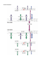
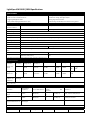
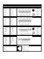
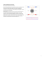
USER MANUAL FOR VIM‐1808 / 0808 Warning for Your Protection 1. Read these instructions 2. Keep these instructions 3. Heed all warnings 4. Follow all instructions 5. Do not use this apparatus near water. 6. Clean only with a dry cloth. 7. Do not block any of the ventilation openings. Install in accordance with the manufacturer’s instructions. 8. Do not install near any heat sources such as radiators, heat registers, stoves, or other apparatus (including amplifiers) that produce heat. 9. Do not defeat the safety purpose of the polarized or grounding‐type plug. A polarized plug has two blades with one wider than the other. A grounding type plug has two blades and a third grounding prong. The wide blade or the third prong are provided for your safety. If the provided plug does not fit into your outlet, consult an electrician for replacement of the obsolete outlet. 10. Protect the power cord from being walked on or pinched, particularly at plugs, convenience receptacles, and the point where they exit from the apparatus. 11. Only use attachments/accessories specified by the manufacturer. 12. Use only with the cart, stand, tripod, bracket, or table specified by the manufacturer, or sold with the apparatus. tip‐over. When a cart is used, use caution when moving the cart/apparatus combination to avoid injury from 13. Unplug this apparatus during lightning storms or when unused for long periods of time. 14. Refer all servicing to qualified service personnel. Servicing is required when the apparatus has been damaged fallen into the in any way, such as power‐supply cord or plug is damaged, liquid has been spilled or objects have apparatus, the apparatus has been exposed to rain or moisture, does not operate normally, or has been dropped. The apparatus shall not be exposed to dripping or splashing. No objects filled with liquids, such as vases, shall be placed on the apparatus. “WARNING To reduce the risk of fire or electric shock, do not expose this apparatus to rain or moisture.” General Installation Instructions Please consider besides these general instructions also any product‐specific instructions in the “Installation” chapter of this manual. Unpacking Check the equipment for any transport damage. If the unit is mechanically damaged, if liquids have been spilled or if objects have fallen into the unit, it must not be connected to the AC power outlet, or it must be immediately disconnected by unplugging the power cable. Repair must only be performed by trained personnel in accordance with the applicable regulations. Installation Site Install the unit in a place where the following conditions are met: The temperature and the relative humidity of the environment must be within the specified limits during operation of the unit. Relevant values are the ones at the air inlets of the unit. Condensation must be avoided. If the unit is installed in a location with large variation of ambient temperature (e.g. in an OB‐van), appropriate precautions must be taken before and after operation. Unobstructed air flow is essential for proper operation. Air vents of the unit are a functional part of the design and must not be blocked in any way during operation (e.g. by objects placed upon them, placement of the unit on a soft surface, or installation of the unit within a rack or piece of furniture). The unit must not be heated up by external sources of heat radiation (sunlight, spot lights). 1 Ambient Temperature Units and systems by LightViper are generally designed for an ambient temperature range (i.e. temperature of the incoming air) of +5...+40 °C. When rack mounting the units, the following facts must be considered: The admissible ambient temperature range for operation of the semiconductor components is 0 °C to +70 °C (commercial temperature range for operation). The air flow through the installation must provide that the outgoing air is always cooler than 70 °C. Average heat increase of the cooling air shall be about 20 K, allowing for an additional maximum 10 K increase at the hot components. In order to dissipate 1 kW with this admissible average heat increase, an air flow of 2.65 m³/min is required. Example: A rack dissipating P = 800 W requires an air flow of 0.8 * 2.65 m³/min which corresponds to 2.12 m³/min. If the cooling function of the installation must be monitored (e.g. for fan failure or illumination with spot lamps), the outgoing air temperature must be measured directly above the modules at several places within Earthing and Power Supply Earthing of units with mains supply (class I equipment) is performed via the protective earth (PE) conductor integrated in the mains cable. Units with battery operation (< 60 V, class III equipment) must be earthed separately. Earthing the unit is one of the measures for protection against electrical shock hazard (dangerous body currents). Hazardous voltage may not only be caused by defective power supply insulation, but may also be introduced by the connected audio or control cables. This equipment may require the use of a different line cord, attachment plug, or both, depending on the available power source at installation. If the attachment plug needs to be changed, refer servicing to qualified service personnel If your unit mains supply is provided via a Neutrik PowerCon™ connector the following precautions must be followed: The PowerCon must be installed and fully engaged before AC power is applied to the unit. The unit must be disconnected from the mains supply before disengaging the PowerCon connector. Class I Equipment (Mains Operation) Should the equipment be delivered without a matching mains cable, the latter has to be prepared by a trained person using the attached female plug (IEC320/C13 or IEC320/C19) with respect to the applicable regulations in your country. Before connecting the equipment to the AC power outlet, check that the local line voltage matches the equipment rating (voltage, frequency) within the admissible tolerance. The equipment fuses must be rated in accordance with the specifications on the equipment. Equipment supplied with a 3‐pole appliance inlet (protection conforming to class I equipment) must be connected to a 3‐pole AC power outlet so that the equipment cabinet is connected to the protective earth. WARNING If the ground is defeated, certain fault conditions in the unit or in the system to which it is connected can result in full line voltage between chassis and earth ground. Severe injury or death can then result if the chassis and earth ground are touched simultaneously. Registration Be sure to register your LightViper product, either by filling in the enclosed Registration Card or by completing the on‐line registration form at our Web site: http://lightviper.com/register If you do so, FiberPlex can contact you with any update information. As enhancements and upgrades are developed, you will be contacted at the registration address. Please read this manual ‐ if you call for technical support, we’ll assume that you have. Please address any inquiries to your dealer or directly to FiberPlex at: FiberPlex Inc. 10840‐412 Guilford Rd. Annapolis Junction, MD 20701 301.604.0100 Fax: 301.604.0773 [email protected] Warranty, Service and Terms and Conditions of Sale For information about Warranty or Service information, please see our published ‘Terms and Conditions of Sale’. This document is available on fiberplex.com or can be obtained by requesting it from [email protected] or calling 301.604.0100. 3 Disposal Disposal of Packing Materials The packing materials have been selected with environmental and disposal issues in mind. All packing material can be recycled. Recycling packing saves raw materials and reduces the volume of waste. If you need to dispose of the transport packing materials, please try to use recyclable means. Disposal of Used Equipment Used equipment contains valuable raw materials as well as materials that must be disposed of professionally. Please return your used equipment via an authorized specialist dealer or via the public waste disposal system, ensuring any material that can be recycled is. Please take care that your used equipment cannot be abused. After having disconnected your used equipment from the mains supply, make sure that the mains connector and the mains cable are made useless. Declarations of Conformity Class A Equipment ‐ FCC Notice This equipment has been tested and found to comply with the limits for a Class A digital device, pursuant to Part 15 of the FCC Rules. These limits are designed to provide a reasonable protection against harmful interference when the equipment is operated in a commercial environment. This equipment generates, uses, and can radiate radio frequency energy and, if not installed and used in accordance with the instruction manual, may cause harmful interference to radio communications. Operation of this equipment in a residential area is likely to cause harmful interference, in which case the user will be required to correct the interference at their own expense. Disclaimer The information in this document has been carefully checked and is believed to be accurate at the time of publication. However, no responsibility is taken by us for inaccuracies, errors, or omissions, nor is any liability assumed for any loss or damage resulting either directly or indirectly from use of the information contained within it. Introduction Congratulations on your purchase of a Light Viper 1808/0808 fiber –optic audio snake; a lightweight, flexible breakthrough for professional sound production. LightViper products are designed, engineered and manufactured by FiberPlex Inc., experts in fiber optics with decades of experience. Our work in audio and data communications products is known in US government applications worldwide. LightViper products combine our fiber optic technology with the highest standards in audio engineering. The VIM‐1808 / 0808 You have purchased the LightViper 1808/0808 system, an 8 x 8 line level analog / AES digital input fiber‐optic transport system (snake). Instead of traditional heavy multi‐conductor copper cable, LightViper fiber optic systems utilize lightweight, flexible, military tactical grade fiber‐optic cable or duplex PVC and plenum rated fiber for installation use. The Fiber Advantage Fiber optics offer many advantages over copper: Transmits light rather than electrons Transmission over greater distances (more than 2 Km [1.25 mile]) Complete electrical isolation Immunity to RFI and EMI Eliminates ground loop problems Can be routed overhead, through walls, or underground Avoids foot traffic while maintaining aesthetics Functional Considerations The Light Viper 1808/0808 is an active device. Because of this, there are some aspects of this new technology that require some slightly different thinking: The Light Viper 1808/0808 system requires AC Power at both the Stage (VIM‐0808) and the console (VIM‐1808) The 1808/0808 system contains (8) Line Level Analog inputs OR (8) AES digital inputs, and (8) analog AND (8) AES digital outputs. There are no microphone preamplifiers as with the 1832 system All inputs exit the snake at Line Level Input and Output flexibility may eliminate the need for some of your outboard gear The LightViper VIM‐1808/0808 is an active device, therefore do not attempt to connect intercom into the returns The returns in the VIM‐1808/0808 cannot be “turned around” to provide (8) sends one way as with a traditional copper snake, as the electronics for the returns are contained in the VIM‐1808. 5 Standard Components In its standard configuration, the Light Viper 1808/0808 is made up of the following primary components. VIM‐1808 The VIM‐1808 contains the system clock. It can be placed at either end (head or tail) of the system. If using an external clock however, the VIM‐1808 needs to be connected to this clock. The VIM‐1808 and VIM‐0808 are identical except that the VIM‐ 1808 contains the system clock and an “external” clock input connector. VIM‐0808 The VIM‐0808 can be placed at either end (head or tail) of the system. Fiber Cable (TFC‐0000‐04) For live production, TFC‐0000‐04 tactical military grade fiber with TAC‐4 Connectors is required between the VIM‐1808 and VIM‐0808. Neutrik OpticalCon® tactical fiber (TFC‐0000‐02‐OC) is also available for similar applications. For installations where the fiber will be pulled through conduit, either VFC‐0000‐D (PVC fiber) or VFC‐0000‐DP (Plenum rated fiber) with ST connector terminations is recommended. There is also an option for a “Pulling Eye” which can be specified by adding an “E” to the part numbers above (VFC‐0000‐DE; VFC‐0000‐DPE). This option includes a strain relief and pulling eye on one end of the fiber optic cable. Lightweight military “tactical grade” fiber ‘cable’ (TFC‐0000‐04) carries the digital signal between LightViper devices. Neutrik OpticalCon® tactical cable is also available. For installation use, either PVC or Plenum rated fiber is recommended (VFC‐0000‐ D, VFC‐0000‐DP). TAC‐4 and OpticalCon® Panels (VPL‐11, VPL‐12 & VPL‐13).These 1U rack panels include (1), (2) or (3) TAC‐4 connectors respectively allowing for connection between the TAC‐4 panel mount connector and the ST connectors on the VIM‐1808/0808. Neutrik OpticalCon panel mount connectors can also be mounted on these panels rather than TAC‐4 connectors. Specify by using the suffix “OC” (Ex. “VPL‐11‐ OC). TAC‐4 and Neutrik OpticalCon connectors can also be fit directly on the chassis of the VIM‐1808/0808 system. In applications such as these, rack ears and VPL panels are not required. All LightViper units come standard with ST connectors unless otherwise specified. Send / Return Cables (VCB‐ADXM, VCB‐ADXF) These cables connect the VIM‐1808/0808 to the analog inputs/outputs of your system. A variety of cables to connect to other digital consoles and devices are also available. Optional Components Additional components can be added to the Light Viper 1808/0808 for increased functionality. DMX4 Lighting Control Interface MD‐3 Multi Control Interface In applications where you want RS‐422, RS‐232 or Midi control in a VIM‐1808/0808 system, a pair of MD‐3 devices will translated this control protocol into TTL data for input to / output of the “Control Circuit” connector on the VIM‐1808 / 0808. **Please refer to page 13 for a complete list and photos of fiber‐optic cable types as well as copper interface cables. Getting Started Setting up and using your Light Viper 1808/0808 system is a quick and simple process. Just follow these steps: 1. Place the VIM‐1808 in a rack near your signal source, and place the VIM‐0808 in a rack near your signal destination and connect AC power 2. Connect and run the Fiber between the two units, and check that the Sync light status is “green” on both units 3. Connect the sends & returns (inputs & outputs) on both units. 4. Connect the analog fan out or digital cables to both units. 5. Input signals and check for audio in both directions. NOTE: the signal output of the VIM‐1808 & VIM‐0808 on the analog outputs is line level. When connecting this system into a console or other device, use line level inputs or engage input pads to achieve optimal signal‐to‐noise ratio. The more advanced functions of the Light Viper VIM‐1808/0808 (control, clocks, etc.) are addressed later in this manual. 7 Indicators and Controls 11 12 13 6 1 2 3 4 7 5 8 9 10 The VIM‐1808 and VIM‐0808 are identical with 2 exceptions – the VIM‐1808 contains the native system clock and an external clock input, and the VIM‐0808 does not. Therefore, only the VIM‐1808 is pictured in this document 1 Analog Outputs The (8) analog line level outputs on the VIM‐1808 are connected via (1) DB25 connectors, (8) channels per DB25 connector. 2 Analog Inputs The (8) inputs are connected via a single DB25 connector. Inputs are line level. 3 Input Selection Switch 4 Digital Inputs The (8) digital returns are connected via a single DB25 connector. Digital inputs are all AES3 compliant. 5 Digital Outputs The (8) AES digital outputs on the VIM‐1832 are connected via (1) DB25 connectors, (8) channels per DB25 connector. 6 Primary Fiber Connection The VIM‐1808 contains a single primary pair of fiber connectors. Always be certain to use appropriate fiber and connectors. LightViper systems use multimode fiber. Single mode optics are available on a custom basis for situations where single mode fiber may already exist. 7 Fiber Thru Connection 8 Control Circuit Connector This RJ45 connector provides (3) bi‐directional CMOS or TTL data lines (up to 38.4KHz from VIM‐0808 to VIM‐1808 and 2MHz from VIM‐1808 to VIM‐0808) plus voltage and GND. This connector is used in conjunction with DGL‐422 cables for transporting Yamaha control, or with MD3 units to transport RS‐422, RS‐232 or MIDI. THIS IS NOT AN ETHERNET CONNECTOR – CONNECTING AN ETHERNET DEVICE TO THIS CONNECTOR COULD DAMAGE THE DEVICE. The pin outs for this connector are detailed in the appendix. Most CMOS or TTL functions / equipment can be adapted to make use of this connector. 9 Sync LED This LED indicates the status of the fiber‐optic link between the VIM‐1808 and VIM‐0808. It has three states; SOLID RED indicates there is no sync present; ALTERNATING RED & GREEN indicates the unit is searching for sync; SOLID GREEN indicates sync is present (optical link) and OFF indicates no power. 10 Power Connector / Fuse The AC power connection to the VIM‐1808 & VIM‐0808 are made via the supplied IEC power cords. The internal power supply can accept 90‐260V at either 50 or 60 Hz> The power fuse is a 5x20mm, 1A Slo‐Blo. Only replace the fuse with an exact match. If after replacement the fuse blows again, contact Fiberplex for service. 11 Word Clock External Input 12 Clock Frequency Switch chooses between analog line level and digital returns 13 Word Clock / Super Clock Output Using the Light Viper VIM‐1808 Standard Connection 9 Pass‐thru Connection Fiber Options Tactical grade military fiber (TAC‐4) Used for live production applications (P/N TFC‐0000‐04). Weighing 8.4 lbs.(12.6kg) for(300)feet, this cable contains (4) fibers and therefore it is capable of carrying the signals of (2) systems on a single cable. The TAC‐4 connectors are hermaphroditic and can be connected to one another. Multimode fiber can transport signals up to 2km (1.25 miles). TAC-4 Neutrik OpticalCon® Fiber This fiber cable contains (2) fibers and is also a tactical grade fiber (P/N TFC‐0000‐02OC). Neutrik OpticalCon Fiber Cable & Panel Mount Connector PVC fiber PVC duplex fiber contains (2) fibers. Plenum rated fiber is also available. The installer can terminate the fiber themselves, or Fiberplex can supply it pre‐terminated. This fiber is also available with a strain relief and “pulling eye” which reduces on site labor. Plenum Install Fiber 11 LightViper VIM‐1808 / 0808 Specifications Specifications • 8 x 8 fiber optic transport system • Cable runs over 1.25 miles with no loss • Rugged, lightweight fiber cable • 24 bit / 96kHz sampling (24/48k with ext. input) • Analog line level OR AES digital input • Simultaneous analog / AES3 digital outputs • Heavy gauge steel construction • Extended range and flexibility means limitless routing options General Specifications Total Harmonic Distortion + Noise*1 Less than 0.01% 1 KHz @ +4 dBu Frequency Response ± 0.5 dB 20‐20kHz @ +16 dBu Dynamic Range 102 dB Crosstalk 5 dB above noise floor Sampling Rate 24 bit / 96kHz or 24 bit / 48 kHz Latency 630 s one way, analog input to digital output, 20s one way, digital input to digital output. Operating Temp 0 to +50°C ambient temperature. Sync LED LED (green) indicates optical link OK, LED (red) indicates problem with optical link, LED (off) indicates no power. AC Power Universal 90‐250 VAC, 50/60 Hz, IEC connector with fuse Max Current Rating VIM‐1808 / VIM‐0808 On / Off Control Date + MIDI RJ‐45 connector for logic level control, CMOS or TTL at 2 MHz max per channel. Dimensions VIM‐1808 / VIM‐0808 1 Rack Unit X 6.5" Deep Weight VIM‐1808 / VIM‐0808 300 ft Fiber Cable (tactical) 6.5 lbs 6 lbs 0.473 mA @ 90V *1‐Hum & Noise are measured with an AES17 compliant filter at 20 kHz. Temperature condition @+10 ‐ +25° C. Input Characteristics Connection Gain Setting Voltage Gain*2 Sensitivity*3 S/N ref +0dBu Overload Clipping Input Impedance Analog Sends 1‐8*4 0 0(0 dB) 1.65 Vrms ‐83 dBu +16 dBu +19 dBu XLR TRS Analog Returns 1‐8 n/a 0(0 dB) 1.65 mVrms ‐83 dBu +16 dBu +19 dBu 2 K Digital sends & Returns 1‐8 (Mixer End) AES3 Digital 1.8 K 10 K *1–Hum & Noise are measured with an AES17 compliant filter at 20 kHz. Temperature condition @+10 ‐ +25° C. *2–0dBu is referenced to 0.775Vrms. *3–Sensitivity is the lowest level that will produce an output of +4dBu (1.23V). Output Characteristics Connection Actual Source Impedance For Use With Nominal Output Level*2 Nominal Max Before Clip Connector*1 Analog Returns 1‐8 (Stage) Box)*1 150 600 Lines +4 dBu (1.23 V) +19 dBu (7 V) DB‐25, Tascam™ DA‐88 pinout, 8 Analog Sends 1‐8 (Mixer) End) 150 600 Lines +4 dBu (1.23 V) +19 dBu (7 V) DB‐25, Tascam™ DA‐88 pinout, 8 channels per connector Digital Sends & Returns 1‐8 AES3 Digital DB‐25, 8 channels per connector *1–All XLR connectors are balanced. *2–0 dBu is referenced to 0.775 Vrms. Optical Characteristics Connector*1 Installation Tension Operating Tension Min Bend Radius Crush Resistance Weight Fiber‐Optic Cable*2 Optical Fiber*3 400 lbs 130 lbs 3.7" 228 lb/in2 19 lbs / 1000' Attenuation Bandwidth Numerical Aperture System Optical Data Rate System Operating Distance 1 dB/Km @1300 nm 500 MHz/Km @ 1300 nm 0.275 122 Mbs 2 Km (1.25 mi) *1–TAC‐4 4 channel SMPTE compliant, *2–Four Channel Tactical Break Out Cable, 0.30"(7.5mm) Outer Diameter, Kevlar™ Strength Member *3–Graded Index, Multimode, Dual Window (850/1300nm) 13 Appendix ANALOG – DB25 Cable Pin Outs 1. 2. 3. 4. 5. 6. 7. 8. 9. 10. 11. 12. 13. Ch. 8 + Ch. 8 G Ch. 7 ‐ Ch. 6 + Ch. 6 G Ch. 5 ‐ Ch. 4 + Ch. 4 G Ch. 3 ‐ Ch. 2 + Ch. 2 G Ch. 1 ‐ Unused 14. 15. 16. 17. 18. 19. 20. 21. 22. 23. 24. 25. Ch. 8 ‐ Ch. 7 + Ch. 7 G Ch. 6 ‐ Ch. 5 + Ch. 5 G Ch. 4 ‐ Ch. 3 + Ch. 3 G Ch. 2 ‐ Ch. 1 + Ch. 1 G ANALOG Connector Pin Outs 1. 2. 3. 4. 5. 6. 7. 8. 9. 10. 11. 12. 13. Ch. 8 + Ch. 8 G Ch. 7 ‐ Ch. 6 + Ch. 6 G Ch. 5 ‐ Ch. 4 + Ch. 4 G Ch. 3 ‐ Ch. 2 + Ch. 2 G Ch. 1 ‐ Unused 14. 15. 16. 17. 18. 19. 20. 21. 22. 23. 24. 25. Ch. 8 ‐ Ch. 7 + Ch. 7 G Ch. 6 ‐ Ch. 5 + Ch. 5 G Ch. 4 ‐ Ch. 3 + Ch. 3 G Ch. 2 ‐ Ch. 1 + Ch. 1 G Digital Connector Pin Outs 1. 2. 3. 4. 5. 6. 7. 8. 9. 10. 11. 12. 13. Ch 1&2 + Ch. 3&4 + Ch 5&6 + Ch. 7&8 + Ch. 9&10 + Ch. 11&12 + Ch. 13&14 + Ch 15 & 16 + Unused Gnd. Unused Gnd. Gnd. 14. 15. 16. 17. 18. 19. 20. 21. 22. 23. 24. 25. Ch 1&2 ‐ Ch. 3&4 ‐ Ch. 5&6 ‐ Ch. 7&8 ‐ Ch. 9&10 ‐ Ch. 11&12 ‐ Ch. 13&14 ‐ Ch. 15&16 ‐ Gnd. Unused Gnd. Gnd. Digital Connector Pin Outs 1. 2. 3. 4. 5. 6. 7. 8. 9. 10. 11. 12. 13. Ch 1&2 + Ch. 3&4 + Ch 5&6 + Ch. 7&8 + Ch. 9&10 + Ch. 11&12 + Ch. 13&14 + Ch 15 & 16 + Unused Gnd. Unused Gnd. Gnd. 14. 15. 16. 17. 18. 19. 20. 21. 22. 23. 24. 25. Ch 1&2 ‐ Ch. 3&4 ‐ Ch. 5&6 ‐ Ch. 7&8 ‐ Ch. 9&10 ‐ Ch. 11&12 ‐ Ch. 13&14 ‐ Ch. 15&16 ‐ Gnd. Unused Gnd. Gnd. Control Circuits RJ‐45 Pin Outs 1. 2. 3. 4. 5. 6. 7. 8. GND TX1 TX2 TX3 RX1 RX2 RX3 VCC +5VDC TAC‐4 Installation Instructions When using TAC‐4 panel mount connectors: Due to the hermaphroditic nature of the TAC‐4 connector, channels 1 & 4 and 2 & 3 are crossed by necessity. Therefore, pins 1 & 2 should always be connected to connectors marked TX and pins 3 & 4 should always be connected to pins marked RX. Pins 1 & 4 are always paired together and pins 2 & 3 will always be paired together. Important Note: A single TAC‐4 connector and cable contains (4) fibers and can transport both pairs of fiber inputs/outputs of the EF‐2 on a single connector / cable. If using Neutrik OpticalCon, two cables / connectors are required, one for each pair, as the OpticalCon cable and connectors contain (2) fibers. When using LC or ST fiber connectors on the chassis of the EF‐2, the connectors are mounted on the rear of the unit. Alternatively these fiber connectors can be mounted on the front panel of the unit. 15 Final Assembly Drawing This page intentionally left blank This page intentionally left blank LV1808UM 8/2011 18040-412 Guilford Rd. • Annapolis Junction, MD 20701 fiberplex.com • [email protected] • 301.604.0100