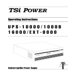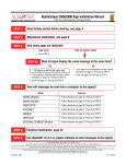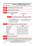
1
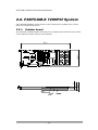
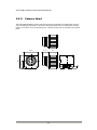
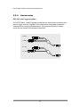
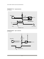
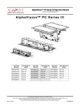
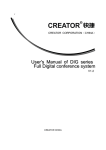
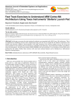
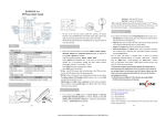
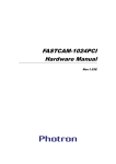
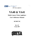
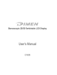
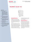
FASTCAM-X 1280PCI
Hardware Manual
Rev.1.0
PHOTRON LIMITED
2002
Table of contents
Table of contents ........................................................................................................... 3
Chapter 1
Introduction ................................................................................................ 5
1.1. Introduction...................................................................................................... 6
1.2. Warranty.......................................................................................................... 7
1.3. How to Use This Manual ................................................................................. 8
1.4. Precautions ..................................................................................................... 9
Chapter 2
Visual Introduction ................................................................................... 11
2.1. Visual Introduction ........................................................................................... 12
2.1.1. Unpacking .............................................................................................. 12
2.1.2. Accessories and Optional Items............................................................. 12
2.2. FASTCAM-X 1280PCI System......................................................................... 13
2.2.1. Grabber board........................................................................................ 13
2.2.2. Camera Head......................................................................................... 14
2.3. Hardware Installation ....................................................................................... 19
2.3.1. Grabber board installation ...................................................................... 19
2.3.2. Camera head installation........................................................................ 20
2.3.3. Imager SETUP CD-ROM installation...................................................... 21
2.4. Multi-Camera Sync Operation.......................................................................... 23
2.4.1. Setting up Master/Slave modes ............................................................. 24
2.4.2. Installing internal sync cables................................................................. 25
2.4.3. Setting camera ID numbers.................................................................... 27
2.4.4. Software setting...................................................................................... 28
2.4.5. Tips for multi-camera sync operation ..................................................... 29
2.5. Gain Selector Switch........................................................................................ 30
Chapter 3
Appendix.................................................................................................. 33
3.1. Specifications ................................................................................................... 34
3.1.1. PHOTRON FASTCAM-X 1280PCI ........................................................... 34
3.1.2. Framing rate vs. Model ............................................................................. 34
3.1.3. Framing rate vs. Image resolution ............................................................ 35
3.1.4. Shutter speed vs. Framing rate................................................................. 35
3.1.5. Recording capacity (number of images) ................................................... 36
3.1.6. PHOTRON FASTCAM-X 1280PCI Camera Head .................................... 37
3.1.7. PHOTRON FASTCAM-X 1280PCI Grabber Board................................... 37
3.2. Dimensions.................................................................................................... 38
3.2.1. Camera head (in millimeters) ................................................................. 38
3.2.2. Grabber board (in millimeters)................................................................ 39
3.3. Remarks ........................................................................................................ 40
3.4. Care of Lenses .............................................................................................. 41
FASTCAM-X1280PCI Series Hardware Manual
Memo
-4-
FASTCAM-X1280PCI Series Hardware Manual
Chapter 1
1.1.
1.2.
1.3.
1.4.
Introduction
Introduction
Warranty
How To Use This Manual
Precautions
-5-
FASTCAM-X1280PCI Series Hardware Manual
1.1.
Introduction
The FASTCAM-X1280PCI High-Speed Video Camera System has been developed to offer a
powerful engineering solution in R and D, engineering, manufacturing, quality control in general
industries and special applications in scientific, medical, biological, aerospace studies. Its
extra-high-speed recording capability and easy-to-use remote control software provide a motion
analysis environment that has been hard to obtain so far.
The live image setup function ensures that the image of the object on the screen is captured
and recorded in the memory at a simple click on the recording button with your mouse. The image
can also be recorded in the HDD of your PC.
Use this cutting-edge recording technology to observe your fast moving object as a slow-motion
playback image or to input the moving image data into your motion analysis system for processing.
This manual has been prepared for you to use the FASTCAM-X1280PCI system in the most
effective way for slow-motion observation and motion analysis of fast moving objects.
Remarks:
1. For the best use of the system, please read through this manual.
2. The content of this manual is based on the best knowledge of the manufacturer. However, in
case any error or missed information is found in this manual, please inform the manufacturer of
such shortcomings. Notwithstanding the above, the manufacturer is not responsible for any results
of the use of this equipment.
3. Copying all or any part of this manual without permission is prohibited.
4. The content of this manual may be changed any time without prior notice.
5. The manufacturer assumes no responsibility for any direct or indirect damage or loss of profit
resulting from the use of this equipment
6. The manufacturer assumes no responsibility for any result of the use of this equipment.
7. Copying all or any part of the software included in this system without prior written permission by
the author is an infringement of copyright.
-6-
FASTCAM-X1280PCI Series Hardware Manual
1.2.
Warranty
New Equipment Warranty
PHOTRON FASTCAM-X1280PCI
PHOTRON LIMITED warrants this PHOTRON FASTCAM-X1280PCI system and its accessories
manufactured by PHOTRON LIMITED, to function properly for one year from the date of shipment,
if the warranty registration card was filled out and returned to PHOTRON USA, INC. or PHOTRON
EUROPE LIMITED within thirty days of shipment.
PHOTRON LIMITED, in conjunction with PHOTRON USA,INC. or PHOTRON EUROPE LIMITED,
agrees to perform the following equipment warranty services:
1. Repair service: If shipped to PHOTRON at any of the addresses shown below, repairs will
be made at no charge.
2. Parts replacement: Replacement parts installed under warranty will be provided at no
charge.
THIS WARRANTY DOES NOT APPLY UNDER THE FOLLOWING CONDITIONS:
Failure to operate the PHOTRON FASTCAM-X1280PCI series in accordance with Photon’s
written instructions, including environmental specifications listed in the User’s Manual.
If there is evidence of the PHOTRON FASTCAM-X1280PCI system being subjected to accidental
damage, misuse or abuse.
If the PHOTRON FASTCAM-X1280PCI system has been repaired or tampered with by persons
other than PHOTRON personnel, customer personnel trained by PHOTRON or without permission
of PHOTRON.
Shipping damage is not covered by this warranty. The purchaser has the responsibility to place a
claim of damage in shipment with the carrier.
PHOTRON LIMITED makes no other warranties, express or implied, including the implied
warranties of merchantability and fitness for a particular purpose. If this PHOTRON
FASTCAM-X1280PCI system does not function properly during the warranty period, PHOTRON
LIMITED will repair it without charge according to the terms stated above. Repair without charge is
PHOTRON LIMITED’s only obligation under this warranty. PHOTRON LIMITED, PHOTRON
USA, INC. or PHOTRON EUROPE LIMITED will not be responsible for any consequential or
incidental damages resulting from the sale, use or improper functioning of this equipment even if
loss or damage is caused by the negligence or other fault of PHOTRON LIMITED, PHOTRON
USA, INC. or PHOTRON EUROPE LIMITED.
Return the equipment that needs warranty service to:
In Americas
PHOTRON USA,INC.
9520 Padgett Street
Suite 110
San Diego, CA 92126-4446
USA
Phone: 858-684-3555
Fax: 858-684-3558
E-mail:[email protected]
In Europe:
PHOTRON EUROPE
LIMITED
Willowbank House
84 Station Road
Marlow, Bucks SL7, U.K.
Phone:+44(0) 1628 89 4353
Fax: +44(0) 1628 89 4354
E-mail:[email protected]
-7-
In other areas:
PHOTRON LIMITED
Shibuya 1-9-8, Shibuya-ku
Tokyo 150-0002
Japan
Phone:+81 3 3486 3471
Fax: +81 3 3486 8760
E-mail:[email protected]
FASTCAM-X1280PCI Series Hardware Manual
1.3.
How to Use This Manual
DEFINITION OF TERMS
You will notice as you read this manual that some of the information is presented as a NOTE,
CAUTION or WARNING. It is important that you understand the significance of these three
terms.
NOTE
A note contains information that we wish to emphasize regarding the operation of your
FASTCAM-PCI series.
CAUTION
A caution is intended to warn you that a certain operation or condition may cause harm to your
FASTCAM-PCI series.
WARNING
A warning is important to the safety of everyone operating the FASTCAM-X1280PCI system and
should not be disregarded under any circumstances.
Chapter 1. Introduction
Contains Warranty, Precautions, Introduction and how to use this manual.
Chapter 2. Visual Introduction
Visual introduction to the components of your FASTCAM-X1280PCI system. Explains the use of
each of connectors and controls on the Camera and the Processor.
Chapter 3. Appendix
Contains specifications and special remarks on the system.
If you require additional information not included in this manual regarding the care, technical
service and operation of your FASTCAM-X1280PCI system please contact the service department
in San Diego by calling:
800 - 585 - 2129
-8-
FASTCAM-X1280PCI Series Hardware Manual
1.4.
Precautions
AMBIENT Temperature
Photron FASTCAM-X1280PCI has been designed to work properly in an ambient temperature
range of 0 to 35 degrees Celsius (32 to 95 degrees Fahrenheit), no condensation.
For the ambient temperature of the PC to be used with FASTCAM-X1280PCI, see the PC manual.
If it has a different working temperature range, the lower of the two different ranges should be
observed.
STORAGE Temperature
FASTCAM-X1280PCI must be stored in a place with an ambient temperature range of -20 to +70
degrees Celsius (-4 to +158 degrees Fahrenheit), no condensation.
TRANSPORTATION
Save the original carton the unit came in for future transportation. Or, if you transport the unit
frequently, the use of a special carrying case is recommended. Please check with your dealer,
Photron USA or Photron Europe. Do not send the unit to a place where the temperature can go
below -20 degrees Celsius (-4 degrees Fahrenheit) or above 70 degrees Celsius (+158 degrees
Fahrenheit).
FEDERAL COMMUNICATIONS COMMISSION
STATEMENTS
Warning: This equipment generates, uses and can radiate radio frequency energy and if not
installed and used in accordance with the instruction manual, may cause interference to radio
communications. It has been tested and found to comply with the limits for a Class
computing device pursuant to Subpart B of Part 15 of the FCC Rules and VDE 0871 Class B
which are designed to provide reasonable protection against such interference when operated in a
commercial environment. Operation of this equipment in a residential area is likely to cause
interference in which case the user at his own expense will be required to take whatever measures
may be required to correct the interference.
This device complies with Part 15 of the FCC Rules and VDE 0871. Operation is subject to the
following two conditions: (1) this device may not cause harmful interference, and (2) this device
must accept any interference received including interference that may cause undesired operation.
WARNING
This product is grounded through the power cord. This protective ground connection is essential
for safe operation of the equipment. Avoid electrical shock by plugging the power cord into a
properly wired receptacle. A loss of the protective ground, for any reason, could result in
electrical shock. Use the proper power cord and insure that it is in good condition.
-9-
FASTCAM-X1280PCI Series Hardware Manual
Memo
- 10 -
FASTCAM-X1280PCI Series Hardware Manual
Chapter 2
Visual Introduction
2.1. Products
2.2. FASTCAM-X1280PCI System
2.3. Hardware Installation
2.4. Multi-Camera Sync Operation
2.5. High Gain Operation
- 11 -
FASTCAM-X1280PCI Series Hardware Manual
2.1. Visual Introduction
2.1.1.
Unpacking
When unpacking, please see if the following items are included in the package:
1. Camera head
2. Grabber board (PCI board)
3. Camera cable (5m)
3. Lens mount cap
5. Driver/application setup CD-ROM
6. Sensor information file FDD(3.5”1.44M)
7. FASTCAM-X1280PCI Hardware manual
8. FASTCAM Control Software operation manual
9. Warranty registration card
10. Internal sync cable (for 2 units)
11. Internal sync cable (for 3/4 units)
2.1.2.
1 ea.
1 ea.
1 ea.
1 ea.
1 ea.
1 ea.
1 ea.
1 ea.
1 ea.
1 ea.
1 ea.
Accessories and Optional Items
The following optional item is offered for the FASTCAM-X1280PCI:
1.
Additional memory board (up to 2 boards can be added)
- 12 -
FASTCAM-X1280PCI Series Hardware Manual
2.2. FASTCAM-X 1280PCI System
The FASTCAM-X1280PCI system consists of such components as a grabber board, camera
head, control software and so forth.
2.2.1.
Grabber board
The FASTCAM- X1280PCI grabber board has been so designed that a maximum of four boards
can be loaded in PCI slots of the PC of ATX standard.
106.7
305.2
7
. 3
9 .
6
1
MEM1
MEM2
- 13 -
MEM3
9
.
2
2
FASTCAM-X1280PCI Series Hardware Manual
2.2.2.
Camera Head
The FASTCAM-X1280PCI camera head, designed with compactness and light weight, ensures
ease of handling and operation in almost any shooting situation with its compactness and light
weight. It uses the F mount for the taking lens. A tripod mounting hole is provided on the camera
base.
36.72
56
13.64
46.48
85.4
85.4
- 14 -
FASTCAM-X1280PCI Series Hardware Manual
2.2.3.
Accessories
EXT OUT and Trigger IN cables
The FASTCAM-X 1280PCI grabber board has two compound connectors that
provide trigger and sync signals in and out between the grabber board and
external devices using dedicated cables. Two external connection cables
come with the system as standard accessories.
1. OUT1
2. OUT2
3. T- TTL
4. T- SW
- 15 -
FASTCAM-X1280PCI Series Hardware Manual
2.2.4.
Specifications of Connectors
The specifications of the FASTCAM-X 1280PCI external connectors are shown here. The
connectors support the following signals:
1. OUT1
2. OUT2
3. T- TTL
4. T- SW
1
EXTOUT1
Output connector
A BNC-type connector. It outputs a signal that indicates the first frame when an asynchronous
reset trigger is input.
2
EXTOUT2
Output connector
A BNC-type connector. It outputs the camera’s vertical sync signal for external strobe and pulse
laser units to synchronize with.
3
TRIGGER TTL IN
Input connector
A BNC-type connector. It accepts external TTL-compatible signal to control the start and end of
recording in a selected recording mode. The input pulse must be of +5V, positive and 50usec wide.
The operational current is 10mA recommended and 20mA maximum.
4
TRIGGER SW IN
Input connector
A BNC-type connector. A contact switch between the center and the shield conductors of the BNC
connector controls the start and end of recording in a selected recording mode.
Caution: Input of trigger signals other than switch contact into TRIGGER SW IN connector will
severely damage the system.
- 16 -
FASTCAM-X1280PCI Series Hardware Manual
TRIGGER TTL IN
Input connector
Circuit diagram
+5V
TRIGGER IN
330
I/O Port
Photocoupler
TLP521(TOSHIBA)
50μsec
+5V
0V
5V TTL level
10mA
TRIGGER START
TRIGGER SW IN
Input connector
Circuit diagram
+5V
+5V
10K
TRIGGER IN
I/O Port
MAX6816
GND
TRIGGER START
- 17 -
FASTCAM-X1280PCI Series Hardware Manual
5.
V SYNC / INTERNAL TRIGGER INPUT connector (BD_IN connector)
This a connector provided specifically to synchronize all the units involved in a multi-camera
operation where two or more FASTCAM-X1280PCI grabber boards are installed in one PC. It
does not support connection or synchronization with external devices or equipment.
When a slave mode is set for multi-camera operation, this connector provides trigger signals from
the master unit to slave(s) for synchronized recording.
6. V SYNC / INTERNAL TRIGGER OUTPUT connector (BD_OUT
connector)
This a connector provided specifically to synchronize all the units involved in a multi-camera
operation where two or more FASTCAM-X1280PCI grabber boards are installed in one PC. It
does not support connection or synchronization with external devices or equipment.
Locations of BD_IN and BD_PUT connectors
BD_OUT
BD_IN
- 18 -
FASTCAM-X1280PCI Series Hardware Manual
2.3. Hardware Installation
Caution
Before you connect between the camera head and grabber board, and install the grabber board
into the PC, please be sure to switch off the PC and unplug the power cord from the mains outlet.
Otherwise, major damages may be caused on your camera head, grabber board and/or PC. Also,
please make sure that there is no twist on the cables.
2.3.1.
Grabber board installation
Follow the below procedure to install the grabber (PCI) board into the PC.
1. Switch off the PC and unplug the power cord.
2. Open up the housing of the PC following the instructions given in the PC user’s manual.
3. Make sure there is an empty PCI slot(s).
4. Remove the metal cover plate over the empty PCI slot.
5. Plug the grabber board in the empty PCI slot. Be sure to press the board firmly so that the board
connector is completely seated in the slot. Fasten the board onto the PC chassis with the
retaining screw.
6. Connect the camera cable from the camera head to the PCI board. Make sure if the orientation
of the connector is correct and fasten it with the retaining screw. Pull the cable lightly to see if
the connector does not come off.
7. Replace the housing cover. Follow the instructions given in the PC manual.
- 19 -
FASTCAM-X1280PCI Series Hardware Manual
2.3.2.
Camera head installation
8. Connect the camera cable between the connector on the camera head and the camera
connector on the grabber board.
Note:
Fasten the connector to the camera head using the retaining screws on the connector shell.
Caution:
Be sure to switch off the PC and unplug the power cord before installing the grabber board in the
PC.
- 20 -
FASTCAM-X1280PCI Series Hardware Manual
2.3.3.
Imager SETUP CD-ROM installation
The mega-pixel C-MOS sensor used in the FASTCAM-X 1280PCI system has been checked
under Photron’s own quality assurance criteria that sets the pixel defect allowance in each of the
geometric areas of the sensor surface. Data from each of the defective pixels on the sensor
surface is replaced with data obtained by calculating data from adjacent pixels. The defect
correction function is programmed in the attached PFV control software. Because the distribution
of defective pixels is unique to each C-MOS sensor, each of the FASTCAM-X 1280PCI must be
installed with the correction data specifically prepared for and attached to it. Use the attached
FASTCAM-X 1280PCI Imager SETUP CD-ROM for installation following the procedure below:
First, made sure the grabber board, driver and PFV have been installed.
Insert the Imager SETUP CD-ROM into the CD drive and set up automatically starts by Auto RUN.
If there is no driver or grabber board installed, the following Initialize Error message is displayed:
If PFV is not installed, you will see the following message:
- 21 -
FASTCAM-X1280PCI Series Hardware Manual
If the sensor serial number of the correction data to be installed and the sensor serial number
imbedded in the grabber board disagree, the following error message appears:
When the preparation is done, execution window is displayed as shown below:
Press the Install button and installation starts. The completion window show up when all is done.
- 22 -
FASTCAM-X1280PCI Series Hardware Manual
2.4. Multi-Camera Sync Operation
The FASTCAM-X1280PCI system offers synchronized multi-camera operation involving up to
four cameras. In the multi-camera sync operation, all the cameras shoot one single fast-moving
event from different viewing angles along the same timeline and record in their respective memory.
This is useful for simultaneously recording a fast-moving object and other related events from
different viewpoints.
The following subsections discuss the procedures for setting up a multi-camera sync operation
system.
The following four steps are needed to set up a multi-camera sync operation:
2.4.1.
2.4.2.
2.4.3.
2.4.4.
Setting up Master/Slave modes on cameras
Connecting cables for internal sync signals
Setting up unique camera ID’s
Setting up PFV software
- 23 -
FASTCAM-X1280PCI Series Hardware Manual
2.4.1.
Setting up Master/Slave modes
For multi-camera sync operation, one of the cameras must be set to be the Master and others
Slave(s). By this, the slave cameras operated in accordance with the sync signal generated by and
fed from the master camera, thus all the cameras operate in a perfect synchronization along one
timeline.
For this setting up, the mode setup switch on the grabber board is used in the following manner:
Caution: Before start working, be sure to switch off the PC and unplug
the power cord.
1) Position of mode setup switches
The mode setup switches are located on the upper surface of the grabber board. See the below
figure to confirm their positions. This figure shows the switches as seen from the top of the board.
ディップスイッチ
DIP SW
4321
ON
2) Setting the switches to sync mode
Set the respective dip switches for the master board and slaves as shown in the below chart.
Switch setting
Master Mode
4321
ON
Functions
Generates sync and trigger signals and output them
from BD_OUT connector.
Switch 3 is OFF
Slave Mode
4321
ON
Follow the master in accordance with the sync signal
fed from the master via BD_IN connector. Starts and
ends recording by the trigger signals fed from master
via BD_IN connector.
Switch 3 is ON
- 24 -
FASTCAM-X1280PCI Series Hardware Manual
2.4.2.
Installing internal sync cables
After Master/Slave set up of the grabber boards, install the sync cables between the boards
1) Position of internal sync connectors
Connectors for internal sync signal input/output are located at the position on the board as shown
below. For multi-camera sync operation, connect between these connectors on respective boards
using the attached cables.
BD_OUT
BD_IN
・BD_IN Connector
Receives internal sync and trigger signals from BD_OUT connector of another board.
・BD_OUT Connector
Outputs internal sync and trigger signals.
- 25 -
FASTCAM-X1280PCI Series Hardware Manual
2) Internal sync cable connection
The following figures show how to connect between the master and slave boards for two- and fourcamera sync operations. Connect the cables so that the sync output (BD_OUT) from the master
board is fed to the sync input (BD_IN) of a slave board.
*Cable connections (2-camera sync operation)
Ex ternal Trigger Input
1s t(M aster )
BD_O UT
BD_IN
2nd(Slave )
BD_O UT
BD_IN
:Internal sy nc c able(f or 2 units)
IL Connec tor, 4 pins IL-S-4 S-S3C2
*Cable connections (4-camera sync operation)
Ex te r n a l Tr ig ge r In p ut
1 s t(M as te r )
B D_ O UT
B D_ IN
2 n d ( S lave )
B D_ O UT
B D_ IN
3 r d ( S lave )
B D_ O UT
B D_ IN
4 th ( S lave )
B D_ O UT
B D_ IN
:In te r n a l Sy nc Ca b le (f o r 3 /4 un its )
IL Co n n e c to r , 4 p ins
IL - S -4 S - S 3 C2
- 26 -
FASTCAM-X1280PCI Series Hardware Manual
2.4.3.
Setting camera ID numbers
For the software to recognize each camera correctly in multi-camera sync operation, the
FASTCAM-X 1280PCI can be assigned an ID number from 0 to 3. By this feature, each of the
cameras is correctly recognized even if the order of camera recognition by the OS changes.
Assign ID numbers in the following manner.
1) Dip switch setting for camera ID
Camera ID number are assigned by setting the dip switches No. 1 and No. 2 as shown in the table
below:
Switch No. 1
Switch No. 2
ON
OFF
OFF
ON
ON
OFF
ON
OFF
ON
ON
ON
ON
ID Number
4321
0
4321
1
4321
2
4321
3
Note: Factory-set ID number is “0”.
Caution: Do not duplicate ID numbers on multiple boards.
- 27 -
FASTCAM-X1280PCI Series Hardware Manual
2.4.4.
Software setting
Hardware setting for multi-camera sync operation has completed in the previous subsections. In
this subsection, how to initialize the internal connections by the control software is discussed. For
the basic operation of the software, please see the Software Operation Manual.
1)
Select a slave camera in the camera selection pull-down box.
2)
Press the More button to start setting details.
3)
Check “Ext Sync In” to enable the external sync mode. Now the slave camera will operate
synchronized to sync and trigger signals from the master.
Note: “Ext Sync In” for master camera is gray out and is not selectable.
4) Repeat the above steps 1) through 3) with all the slave cameras.
This concludes the software setting procedure.
- 28 -
FASTCAM-X1280PCI Series Hardware Manual
2.4.5.
Tips for multi-camera sync operation
Triggering from software
With the internal sync cables connected (see subsection 2.4.2), software triggering can be done to
all the boards without any delay between them.
Using external trigger
You can use external triggers for multi-camera sync operation. Input a trigger to the master board
from an external source. The trigger is then transferred to slave boards for sync operation.
Note: Input of an external trigger to a slave is invalid: it will not be recognized as a trigger.
Note: Triggering takes place in all the boards, the master and slave(s), set up for sync operation all
at one time in synchronization. In the multi-camera sync operation system, no individual board can
be triggered independently from others.
- 29 -
FASTCAM-X1280PCI Series Hardware Manual
2.5. Gain Selector Switch
The gain switch on the back of the camera lets you select the camera gain (analog) setting from
the following two modes:
Standard gain mode
High gain mode (+6dB)
In a lower-light level situation, the high gain mode may be helpful. Note, however, you need to be
careful when using it because it will raise the overall noise level to a certain degree.
Normal
High
Gain Switch
Note: Factory setting is “Standard”.
Note: High gain will raise the overall noise level to a certain degree.
- 30 -
FASTCAM-X1280PCI Series Hardware Manual
Memo
- 31 -
FASTCAM-X1280PCI Series Hardware Manual
Memo
- 32 -
FASTCAM-X1280PCI Series Hardware Manual
Chapter 3 Appendix
3.1. Specifications
3.2. Dimensions
3.3. Remarks
3.4. Care of Lenses
- 33 -
FASTCAM-X1280PCI Series Hardware Manual
3.1. Specifications
3.1.1. PHOTRON FASTCAM-X 1280PCI
Recording method
START
END
CENTER
MANUAL
RANDOM
Framing rate
Full frame
Partial frame
Models
Digital recording in memory board (SD-RAM)
Records frames to the maximum of the recording memory,
and stops.
Stops recording at a trigger.
Records the same number of frames before and after a
trigger.
Records preset number of frames before and after a
trigger.
Records from 1 up to 256 frames, as preset, at each
trigger. The number is set by control software.
START and RANDOM modes support Random reset
trigger that is on/off switchable by control software.
60; 125; 250; 500 FPS
1000; 2000; 4000; 8000; 16000 FPS
500, 1k, 4k and 16k
3.1.2. Framing rate vs. Model
Model
Framing rate
(FPS)
500
1k
4k
16k
60
○
○
○
○
125
○
○
○
○
250
○
○
○
○
500
○
○
○
○
1000
-
○
○
○
2000
-
-
○
○
4000
-
-
○
○
8000
-
-
-
○
16000
-
-
-
○
- 34 -
FASTCAM-X1280PCI Series Hardware Manual
3.1.3. Framing rate vs. Image resolution
Framing rate (FPS)
Resolution
(pixels)
60
125
250
500
1280x1024
○
○
○
1280x512
○
○
○
1000
2000
4000
8000
16000
○
-
-
-
-
-
○
○
-
-
-
-
640x512
○
○
○
○
○
-
-
-
-
1280x256
○
○
○
○
○
○
-
-
-
640x256
○
○
○
○
○
○
-
-
-
320x256
○
○
○
○
○
○
-
-
-
640x128
○
○
○
○
○
○
○
-
-
320x128
○
○
○
○
○
○
○
-
-
160x128
○
○
○
○
○
○
○
-
-
640x64
○
○
○
○
○
○
○
○
-
320x64
○
○
○
○
○
○
○
○
-
160x64
○
○
○
○
○
○
○
○
-
80x64
○
○
○
○
○
○
○
○
-
320x32
○
○
○
○
○
○
○
○
○
160x32
○
○
○
○
○
○
○
○
○
3.1.4. Shutter speed vs. Framing rate
Framing rate (FPS)
Shutter speed
60
125
250
500
1000
2000
4000
8000
16000
1/60s
○
-
-
-
-
-
-
-
-
1/125s
○
○
-
-
-
-
-
-
-
1/250s
○
○
○
-
-
-
-
-
-
1/500s
○
○
○
○
-
-
-
-
-
1/1000s
○
○
○
○
○
-
-
-
-
1/2000s
○
○
○
○
○
○
-
-
-
1/4000s
○
○
○
○
○
○
○
-
-
1/8000s
○
○
○
○
○
○
○
○
-
1/16000s
○
○
○
○
○
○
○
○
○
1/32000s
○
○
○
○
○
○
○
○
○
1/64000s
○
○
○
○
○
○
○
○
○
1/128000s
○
○
○
○
○
○
○
○
○
- 35 -
FASTCAM-X1280PCI Series Hardware Manual
3.1.5. Recording capacity (number of images)
The following three models are available of FASTCAM-X 1280PCI:
-1 Model (1.28GB Memory)
-2 Model (2.56GB Memory)
-3 Model (3.84GB Memory)
Memory capacity
Resolution (pixels)
1.28GB
2.56GB
3.84GB
No. of frames
No. of frames
No. of frames
1280x1024
1024
2048
3072
1280x512
2048
4096
6144
640x512
4096
8192
12288
1280x256
4096
8192
12288
640x256
8192
16384
24576
320x256
16384
32768
49152
640x128
16384
32768
49152
320x128
32768
65536
98304
160x128
65536
131072
196608
640x64
32768
65536
98304
320x64
65536
131072
196608
160x64
131072
262144
393216
80x64
262144
524288
786432
320x32
131072
262144
393216
160x32
262144
524288
786432
Note: The recording time is calculate as follows:
Recording time = No. frames x (1/frame rate)
- 36 -
FASTCAM-X1280PCI Series Hardware Manual
3.1.6. PHOTRON FASTCAM-X 1280PCI Camera Head
Sensor resolution
Grayscale
Lens mount
Dimensions
Camera cable
Data bus I/F
Power
High gain feature 1
(Analog gain selection)
Sensor output range
selection
1280 x 1024 pixels
Mono
8 bits
Color
8 bits each RGB (Bayer color filter)
F mount (Nikon)
85.4(W)x85.4(H)x56.0(L)mm
(Excl. lens mount, camera mount plate)
5 meters (not expandable)
PanelLink Standard (Photron-modified)
5VDC power fed by grabber board via camera cable
NEVER remove camera cable while PC is powered on.
Gain selectable between Standard and High Gain Switch on camera
back plate
Selectable by control software from Upper 8 bits(default) / Middle 8 bits
/ Lower 8 bits
Caution:
NEVER remove the camera cable while the PC is powered on. Be sure to
shut down the PC before removing the camera cable.
3.1.7. PHOTRON FASTCAM-X 1280PCI Grabber Board
PCI Standard
Board size
LIVE display
High gain feature 2
External trigger input
BD_IN/BD_OUT connectors
Sync signal input
External output signal 1
(EXT OUT1)
PCI Rev2.1 Specificaiotn
PCI full size standard (with memory board installed)
Uses one PCI slot when one memory board is installed
Uses two PCI slots when two or more memory boards installed
Displays LIVE image while recording in memory
Gain factors x 1(default), x 2(+0.7F), x 4(+1.0F), and x 8(+1.3F)
selectable by control software “Sensitivity”
TTL input
+5V/10mA, Positive going
Contact input
Used for sync between FASTCAM-X1280PCI cameras
Vertical sync signal 3.3Vp-p, Negative going
Random reset trigger timing signal (+5V TTL)
Memory recording indication signal (+5V TTL)
Selected from above two by control software
External output signal 2
(EXT OUT2)
Vertical sync signal +5V TTL
Power consumption
25W max. (+5VDC, 2.5A; +3.3VDC, 2.5A)
(incl. Camera head power consumption)
- 37 -
FASTCAM-X1280PCI Series Hardware Manual
3.2.
3.2.1.
Dimensions
Camera head (in millimeters)
36.72
56
13.64
46.48
85.4
85.4
- 38 -
FASTCAM-X1280PCI Series Hardware Manual
Grabber board (in millimeters)
7
. 3
9 .
6
1
9
.
2
2
MEM1
MEM2
MEM3
305.2
106.7
3.2.2.
- 39 -
FASTCAM-X1280PCI Series Hardware Manual
3.3.
Remarks
1. Each individual system has its own characteristics and may differ from others in the following
aspects:
・It may display a slight lack of brightness uniformity across the entire screen.
・It may have an exceptionally bright horizontal line in the lower end of the image (monochrome
model).
・It may display a slight lack of color uniformity on one or two horizontal lines in the upper, leftmost
or rightmost portion(s) of the screen.
2. When using the higher-gain features (Gain Switch on the camera head, Sensor output range
and/or Sensitivity setting), please note the following inevitable drawbacks:
・
・
・
・
Noise level gets higher.
Color balance needs readjustment.
Color uniformity is lowered across the entire screen.
The sensitivity gets less linear (lower grayscale).
Please note all the above are due entirely to the basic characteristics and specifications of the
C-MOS sensors used in the system and should not be interpreted as defects.
- 40 -
FASTCAM-X1280PCI Series Hardware Manual
3.4.
Care of Lenses
The surface of photographic lenses has thin coatings that reduce chromatic aberration, unwanted
reflections, and other distortions. Extra care should be taken to protect this fragile coating.
Protect the lens by installing a lens cap when you are not using the camera. Brush the lens gently
with a camel hairbrush or loosely folded piece of lens paper to remove dust particles. For stubborn
dirt use photographic lens cleaning solution and lens wipes. Never rub the lens with direct
pressure or drop cleaning solution directly on the lens surface.
- 41 -
FASTCAM-X1280PCI Series Hardware Manual
- 42 -
In Americas:
PHOTRON USA, INC.
9520 Padgett Street, Suite 110
San Diego, CA 92126-4446, USA
Phone: 858-684-3555
Fax:
858-684-3558
E-mail: [email protected]
In Europe:
PHOTRON EUROPE LIMITED
Willowbank House
84 Station Road
Marlow, Bucks SL7 1NK, U.K.
Phone: +44(0) 1628 89 4353
Fax: +44(0) 1628 89 4354
E-mail: [email protected]
In other areas:
PHOTRON LIMITED
Shibuya 1-9-8, Shibuya-Ku
Tokyo 150-0002, Japan
Phone: +81 3 3486 3471
Fax:
+81 3 3486 8760
E-mail: [email protected]
FASTCAM-X 1280PCI User’s Manual
English Version
May. 2002
Rev.1.0
FASTCAM-X 1280PCI User’s Manual
2002 PHOTRON LIMITED