1
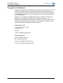
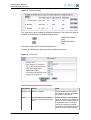
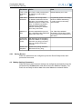
Arctic Modbus Gateway
Arctic Modbus Gateway (2260)
Firmware Version x.x.x
Document Version 1.0
June 2010
Configuration Manual
Arctic Modbus Gateway
Copyright and Trademark
Copyright © 2008-2010, Viola Systems Ltd. All rights to this manual are owned
solely by Viola Systems Ltd. (referred elsewhere in this User’s Manual as
Viola Systems). All rights reserved. No part of this manual may be transmitted
or reproduced in any form or by any means without a prior written permission
from Viola Systems.
Ethernet™ is a trademark of XEROX Corporation. Windows™ and Internet
Explorer™ are trademarks of Microsoft Corporation. Netscape™ is a
trademark of Netscape Communications Corporation. All other product names
mentioned in this manual are the property of their respective owners, whose
rights regarding the trademarks are acknowledged.
Viola Systems Ltd.
Lemminkäisenkatu 14-18 A
FI-20520 Turku
Finland
E-mail: [email protected]
Technical Support
Phone: +358 20 1226 226
Fax: +358 20 1226 220
E-mail: [email protected]
Internet: http://www.violasystems.com
Firmware Version x.x.x
2
Document Version 1.0
Configuration Manual
Arctic Modbus Gateway
Disclaimer
Viola Systems reserves the right to change the technical specifications
or functions of its products or to discontinue the manufacture of any of its
products or to discontinue the support of any of its products without any
written announcement and urges its customers to ensure that the information
at their disposal is valid.
Viola software and programs are delivered “as is”. The manufacturer does not
grant any kind of warranty including guarantees on suitability and applicability
to a certain application. Under no circumstance is the manufacturer or the
developer of a program responsible for any damage possibly caused by the
use of a program. The names of the programs as well as all copyrights relating
to the programs are the sole property of Viola Systems. Any transfer, licensing
to a third party, leasing, renting, transportation, copying, editing, translating,
modifying into another programming language or reverse engineering for any
intent is forbidden without the written consent of Viola Systems.
Viola Systems has attempted to verify that the information in this manual is
correct with regard to the state of products and software on the publication
date of the manual. We assume no responsibility for possible errors which
may appear in this manual. Information in this manual may change without
prior notice from Viola Systems.
Firmware Version x.x.x
3
Document Version 1.0
Configuration Manual
Arctic Modbus Gateway
Declaration of Conformity
(according to ISO/IEC Guide 22 and EN 45014)
Manufacturer’s Name: Viola Systems Ltd.
Manufacturer’s Address:
Lemminkäisenkatu 14-18 A
FI-20520 Turku
Finland
declares that this product:
Product Name:
conforms to the following standards:
EMC:
EN 55022 Emission Test (Class A)
1. Radiated Emissions (30-1000MHz)
2. Conducted Emissions (0.15-30MHz)
EN 50082-1 Immunity Test
1. IEC 801-3: Radio Frequency Electromagnetic Field
2. IEC 801-2: Electrostatic Discharge
3. IEC 801-4: Fast Transients, AC Power Ports and Signal cables
Supplementary Information:
“The product complies with the requirements of the Low Voltage Directive
73/23/EEC and EMC directive 89/336/EEC.”
Warning!
This is a Class A product. In a domestic environment this product may cause
radio Interference which may make it necessary for the user to take adequate
measures.
Manufacturer’s Contact Information:
Viola Systems Ltd.
Lemminkäisenkatu 14-18 A
FI-20520 Turku
Finland
Phone: +358 20 1226 226
Fax: +358 20 1226 220
Firmware Version x.x.x
4
Document Version 1.0
Configuration Manual
Arctic Modbus Gateway
Warranty and Safety Instructions
Read these safety instructions carefully before using the products mentioned
in this manual:
Warranty will be void if the product is used in any way in contradiction with the
instructions given in this manual or if the product has been tampered with.
The devices mentioned in this manual are to be used only according to the
instructions described in this manual. Faultless and safe operation of the
devices can be guaranteed only if the transport, storage, operation and
handling of the devices is appropriate. This also applies to the maintenance of
the products.
To prevent damage both the product and any terminal devices must always
be switched OFF before connecting or disconnecting any cables. It should
be ascertained that different devices used have the same ground potential.
Before connecting any power cables the output voltage of the power supply
should be checked.
This product is not fault-tolerant and is not designed, manufactured
or intended for use or resale as on-line control equipment or as part
of such equipment in any hazardous environment requiring fail- safe
performance, such as in the operation of nuclear facilities, aircraft navigation
or communication systems, air traffic control, direct life support machines,
or weapons systems, in which the failure of Viola Systems manufactured
hardware or software could lead directly to death, personal injury, or severe
physical or environmental damage.
Firmware Version x.x.x
5
Document Version 1.0
Configuration Manual
Arctic Modbus Gateway
Revisions
Date
Document Firmware Description of changes
Version
Version
06/2010
1.0
Firmware Version x.x.x
Lay-out changed
6
Document Version 1.0
Configuration Manual
Arctic Modbus Gateway
Contents
COPYRIGHT AND TRADEMARK ........................................................................................ 2
DISCLAIMER..........................................................................................................................3
DECLARATION OF CONFORMITY...................................................................................... 4
WARRANTY AND SAFETY INSTRUCTIONS.......................................................................5
REVISIONS............................................................................................................................ 6
1. INTRODUCTION............................................................................................................... 8
2. PARAMETERS.................................................................................................................. 9
2.1
2.2
2.3
Common parameters.............................................................................................................9
2.1.1 General Settings....................................................................................................... 9
2.1.2 Gateway Mode.......................................................................................................... 9
2.1.3 Protocols....................................................................................................................9
2.1.4 Framing................................................................................................................... 10
2.1.5 Exceptions............................................................................................................... 11
2.1.6 Serial Settings......................................................................................................... 11
2.1.7 Network Settings..................................................................................................... 13
Routes..................................................................................................................................14
Saving Parameters.............................................................................................................. 16
3. CONFIGURING NETWORK MASTER TO SERIAL SLAVES MODE.............................17
3.1
3.2
Settings – Common parameters......................................................................................... 17
Saving Parameters.............................................................................................................. 19
4. CONFIGURING SERIAL MASTER TO NETWORK SLAVES MODE.............................20
4.1
4.2
4.3
Settings – Common Parameters.........................................................................................20
4.1.1 Saving Common Parameters..................................................................................22
Settings – Routes................................................................................................................22
4.2.1 Saving Routes.........................................................................................................24
Making Settings Permanent................................................................................................ 24
LIMITED WARRANTY......................................................................................................... 25
TECHNICAL SUPPORT ..................................................................................................... 26
Firmware Version x.x.x
7
Document Version 1.0
Configuration Manual
Arctic Modbus Gateway
1 Introduction
This Configuration guide is intended only for configuring Modbus on Viola
Arctic device. It therefore presents only Modbus specific functionality. If you
need to know more about general Arctic configuration, please refer to Arctic
User's Manual. This User's Manual should be shipped with Arctic products or it
could be obtained by contacting Viola Systems.
The Modbus Gateway is an adapter application enabling conversions between
Serial and Network Modbus protocols. The gateway can operate on two
modes; either connecting serial Masters to Slaves behind the network or
connecting network Master to Serial slaves.
The gateway offers following core properties:
■ Supports Modbus RTU and Modbus ASCII serial protocols.
■
Supports ModbusTCP, ModbusRTU over TCP, ModbusRTU over UDP,
Modbus ASCII over TCP and Modbus ASCII over UDP network protocols.
■
It can generate and filter out gateway exceptions.
■
It can route traffic on network based on Modbus addressing enabling
intelligent use of network resources.
■
Makes automatic connection management.
■
Enables multiple server sessions over network.
■
Offers unlimited amount of Masters on serial or Network side.
■
Offers 30 routes over network to slaves.
Firmware Version x.x.x
8
Document Version 1.0
Configuration Manual
Arctic Modbus Gateway
2 Parameters
The parameters are divided into two groups:
■ Common parameters
■
Routes
Common parameters define for e.g. the protocols used in serial and network
communications, serial port settings and protocol specific timeouts. Route
parameters are only required on Serial Master to Network Slaves mode
defining the IP and Modbus addresses of slaves behind the network.
2.1
Common parameters
The common parameters define general settings and settings for Network
Master to Serial Slaves mode.
2.1.1
General Settings
Gateway Status
Table 1: Gateway Status
Identifier
Gateway Status
Description
Tthe Modbus gateway functionality enabled for the serial port.
Values
Enabled – Modbus Gateway is enabled
Disabled – Modbus Gateway is not enabled
Notes
2.1.2
Each serial port of Arctic has it’s own Modbus Gateway definitions.
Gateway Mode
Table 2: Gateway Mode
Identifier
Gateway Mode
Description
The slaves located on network or serial side.
Values
Network Master to Serial Slaves – Slaves are on serial side.
Serial Master to Network Slaves – Slaves are on network side.
Notes
2.1.3
If slaves are on network side, the routes are also needed to be
defined.
Protocols
Serial Protocol
Table 3: Serial Protocol
Identifier
Serial Protocol
Description
Defines the Modbus protocol used on serial communication.
Firmware Version x.x.x
9
Document Version 1.0
Configuration Manual
Arctic Modbus Gateway
Identifier
Serial Protocol
Values
Modbus RTU – Serial devices use Modbus RTU protocol
Modbus ASCII – Serial devices use Modbus ASCII protocol
Notes
Modbus RTU is more efficient and should be used whenever
possible.
Network Protocol
Table 4: Network Protocol
Identifier
Network Protocol
Description
Defines the TCP/IP and Modbus protocol used on network
communication.
Values
Modbus TCP – Modbus TCP protocol over TCP
Modbus RTU over TCP – Modbus RTU protocol over TCP
Modbus RTU over UDP – Modbus RTU protocol over UDP
Modbus ASCII over TCP – Modbus ASCII protocol over TCP
Modbus ASCII over UDP – Modbus ASCII protocol over UDP
Notes
2.1.4
If Viola Systems M2M Gateway is used to tunnel network traffic
over SSH, use Modbus RTU over UDP when possible for efficient
communication. The SSH tunnel already contains TCP properties like
reliable message delivery.
Framing
Slave Response Timeout
Table 5: Slave Response Timeout
Identifier
Slave response timeout
Description Defines the time in microseconds (10E-6 seconds) how long Arctic
waits the response from Modbus slave. If the response is not received,
Arctic can generate and return Modbus gateway exception.
Values
0 – 90 000 000 microseconds (0 – 90 seconds)
Notes
The reply timeout of Modbus Master must be greater than the Gateway
(Arctic) timeout. Otherwise the flow of request-reply communication is
violated. Arctic does not accept a new request before the reply from
slave is received or the reply timeout is elapsed. The delays in network
communication can vary especially in wireless (e.g. GPRS/EDGE/
Mobitex) networks. When the slaves are located on network side, use
e.g. PING to estimate the delay packets spend on network.
Firmware Version x.x.x
10
Document Version 1.0
Configuration Manual
Arctic Modbus Gateway
Inter-Frame Timeout
Table 6: Inter-Frame Timeout
2.1.5
Identifier
Inter-frame timeout
Description
Defines the idle time in microseconds (10E-6 seconds) that marks the
end of Modbus frame in serial communication. If the value is zero, the
Gateway uses standard 4 character time.
Values
0 … 2 000 000 microseconds (0 – 2 seconds)
Notes
Use as small value as possible to speed up communication and
increase the value if problems arise. Some PC programs can insert
unexpected delays between serial characters.
Exceptions
Generate Gateway Exceptions
Table 7: Generate Gateway Exceptions
Identifier
Generate Gateway exceptions
Description Defines does the Gateway generate and return Modbus Gateway
exception message to Master if no valid reply is not received from
slave.
Values
Enabled – Generation of Gateway exceptions is enabled
Disabled - Generation of Gateway exceptions is disabled
Notes
This functionality is useful for debugging. See also parameter “Pass
Gateway exceptions”.
Pass Gateway Exceptions
Table 8: Pass Gateway Exceptions
Identifier Pass Gateway exceptions
Description Defines are the Gateway exception replies from slave side passed to
master.
Values
Enabled – Gateway exception replies are passed to Master
Enabled – Gateway exception replies are passed to Master
Notes
2.1.6
filtered away Notes
Serial Settings
Serial Port
Table 9: Serial Port
Identifier
Serial Port
Description Defines the serial port that Gateway uses for Modbus serial
communication.
Firmware Version x.x.x
11
Document Version 1.0
Configuration Manual
Arctic Modbus Gateway
Identifier
Serial Port
Values
Port 1 – Serial port 1 (RS-232 console/application port)
Port 2 – Serial port 2 (RS-232/422/485 application port)
Notes
If a single serial port or RS-422/485 is required, use Port 2. If Port 1 is
used, the console switch of Arctic must be on Application position. DIPswitches below the DB-9 serial connector specify the RS-232/422/485
settings of Port 2.
Serial Speed
Table 10: Serial Speed
Header 1
Speed
Description Defines the serial port speed for Modbus communication.
Values
300, 1200, 2400, 4800, 9600, 19200, 38400, 57600, 115200 bps
Notes
Check the speeds supported by connected Modbus equipment. If
special serial port speed is required, please contact Viola Systems.
Serial Data Bits
Table 11: Serial Data Bits
Identifier
Serial Data bits
Description Defines the number of data bits used on Modbus serial
communications.
Values
5, 6, 7, 8, Auto (8 for Modbus RTU, 7 for Modbus ASCII)
Notes
Check the data bits supported by connected Modbus equipment.
Generally Modbus RTU communication uses 8 data bits and Modbus
ASCII communication uses 7 data bits.
Serial Stop Bits
Table 12: Serial Stop Bits
Identifier
Serial Stop bits
Description
Defines the number of stop bits used on Modbus serial
communications.
Values
1,2
Notes
Serial Parity
Table 13: Serial Parity
Identifier
Serial Parity
Description
Defines the parity method used on Modbus serial communication
Firmware Version x.x.x
12
Document Version 1.0
Configuration Manual
Arctic Modbus Gateway
Identifier
Serial Parity
Values
None – no parity method used
Even – even parity bit generated and inspected
Odd – odd parity bits generated and inspected
Notes
Serial Flow Control
Table 14: Serial Flow Control
Identifier
Serial Flow control
Description
Defines is the hardware (RTS/CTS) flow control used on Modbus serial
communication
Values
Enabled – RTS/CTS flow control used
Disabled – RTS/CTS flow control not used
Notes
2.1.7
Use of hardware flow control is suggested
Network Settings
Server TCP/UPD Port
Table 15: Server TCP/UPD Port
Identifier
Server TCP/UDP port
Description
Defines the TCP or UDP port that Masters can form connections to.
Default Modbus TCP/IP communication port is 502.
Values
1 - 32500
Notes
If multiple Modbus Gateways are running on same device (for both
serial ports) the TCP/UDP communication ports must not be same.
Use e.g. ports 502 and 504. The network and Arctic firewalls must
enable TCP or UDP communication for that port.
Maximum Number of Clients
Table 16: Maximum Number of Clients
Identifier
Maximum number of clients
Description
Defines how many network masters can be connected to Gateway
simultaneously.
Values
0-20
Notes
Generally use value at least 2 when using TCP communication.
Otherwise if the Gateway does not recognize partially closed
connection, forming of new connections is not accepted by Gateway
before “Connection idle timeout” is elapsed.
Firmware Version x.x.x
13
Document Version 1.0
Configuration Manual
Arctic Modbus Gateway
Connection Idle Timeout
Table 17: Connection Idle Timeout
Identifier Connection idle timeout
Description If the connected Master hasn’t sent valid Modbus packets during that
timeout the connection is closed by Arctic and therefore the resources
are available for new connections. This parameter is especially useful
when the network connection is not reliable causing ’hanging’ or
partially closed connections.
Values
0 – 32500 seconds
Notes
Set this value about two times the polling interval of master.
Enable Keepalive
Table 18: Enable Keepalive
Identifier Enable keepalive
Description Defines is the connection testing enabled for TCP network
communication.
Values
Enabled – Testing the TCP connection with Master is enabled
Disabled – Testing the TCP connection with Master is disabled
Notes
2.2
The testing is done by sending TCP keepalive packets on certain
intervals.
Routes
When the Arctic Modbus Gateway is configured to Serial Master to Network
Slaves mode the routes are needed to be defined for each connected Modbus
slave. Gateway can route traffic based on Modbus addressing therefore
enabling more efficient communication where each slave receives only data
addressed to it.
Route in Use
Table 19: Route in Use
Identifier
Route in use
Description
Defines is this route entry used to decide to which IP address
Modbus request is sent.
Values
Yes – Route information is used
No – Route information is not used
Notes
Firmware Version x.x.x
If no route is found for Modbus request is it dropped and
Gateway exception is generated if enabled.
14
Document Version 1.0
Configuration Manual
Arctic Modbus Gateway
Host
Table 20: Host
Identifier
Host
Description
Defines the IP address or Host name where packets are routed
by that entry.
Values
IP address or Host name
Notes
If Host names are used the DNS server IP address is required
to be defined on Arctic Network settings. The Network Protocol
setting on “Common parameters” defines the network- and
Modbus protocol used on network communication.
TCP or UDP Destination Port
Table 21: TCP or UDP Destination Port
Identifier
TCP or UDP destination port
Description
Defines the UDP or TCP destination port where this route entry
sends Modbus requests.
Values
0 – 32500 (Modbus default is 502)
Notes
The port must be same as used on the network slave device or
Gateway behind network.
Filter Slave Address
Table 22: Filter Slave Address
Identifier
Filter slave address
Description
Defines is the routing based on Modbus addresses used for
that entry. If not enabled every Modbus request is routed to
this entry. If enabled only Modbus requests having destination
address matching the Address list of entry are routed.
Values
Yes – Route entry checks for Modbus destination address
No – Route entry enables any Modbus destination address
Notes
It’s generally good to use Modbus address filtering avoiding
unnecessary network traffic.
Address to Filter
Table 23: Address to Filter
Identifier
Address to filter
Description
Comma separated list of the Modbus addresses of slaves
behind on this route entry (max. 20 pcs.).
Values
Maximum 20 pcs. of comma (,) separated Modbus destination
addresses.
Firmware Version x.x.x
15
Document Version 1.0
Configuration Manual
Arctic Modbus Gateway
Identifier
Address to filter
Notes
The “Filter Slave address” parameter of Route entry needs to be
enabled these addresses to take effect.
Connection Idle Timeout
Table 24: Connection Idle Timeout
Identifier
Connection idle timeout
Description
If there hasn’t been communication on this route during given
amount of seconds the Gateway automatically closes the TCP
connection to slave and therefore frees Slave’s communication
resources. This is especially useful when multiple Masters
access same Slave.
Values
0 – 32500 seconds
Notes
Set this parameter about two times the polling interval of
Master.
Enable TCP Keepalive
Table 25: Enable TCP Keepalive
Identifier
Enable TCP keepalive
Description
Defines is the connection testing enabled for TCP network
communication.
Values
Enabled – Testing the TCP connection with Slave is enabled
Enabled – Testing the TCP connection with Slave is enabled
Notes
2.3
The testing is done by sending TCP keepalive packets on
certain intervals.
Saving Parameters
When the settings are complete, press the Apply button and permanently
store the parameters by clicking on Commit button. Now reboot the Arctic by
pressing Reboot button. The Arctic is now ready to deliver data from Network
Masters to Serial Slaves.
Firmware Version x.x.x
16
Document Version 1.0
Configuration Manual
Arctic Modbus Gateway
3 Configuring Network Master to Serial Slaves Mode
When the PLC/RTU slaves supporting serial based Modbus communication
are required to be controlled over TCP/IP networks the Gateway on slave side
needs to be configured to Network Master-Serial Slaves mode.
Figure 1. Arctic Modbus Gateway connecting serial slaves to network
On that mode, the Arctic Modbus Gateway acts like network server where
Masters (clients) can connect (the default port being 502) and transmit
Modbus requests. The Gateway makes conversions between network and
serial protocols. If the slave does not reply during defined timeout or if the
reply is corrupted, the Gateway sends “gateway exception message” back to
Master if the exception generation is enabled. Otherwise, the reply is returned.
Multiple masters can connect simultaneously to Gateway, which handles the
multiplexing between masters.
Note!
Each Arctic Modbus Gateway must have a fixed IP address in order the
Master to know where to connect. Many client-use optimized networks (like
public GPRS, xDSL) does not offer fixed IP addresses but allocate them
dynamically. This situation can be solved by using Viola Systems M2M
Gateway.
3.1
Settings – Common parameters
Only the common parameters are configured. The routes are unused on
Network Master to Serial Slaves mode. The configuration menu is located on
Applications -> Modbus GW menu of Arctic WEB configuration.
Firmware Version x.x.x
17
Document Version 1.0
Configuration Manual
Arctic Modbus Gateway
Figure 2. Example of common parameters for Network Master to Serial
Slaves mode
Table 26: Setting guideline for Network Master to Serial Slaves mode
Parameter Value Note
Parameter
Value
Note
Gateway Status Enabled
Gateway Mode Network Master to Serial Slaves
Serial Protocol
Depends on connected Modbus
slave
Prefer Modbus RTU when
possible
Network
Protocol
Depends on Master side
If Viola Systems M2M tunneling
is used, prefer UDP based
Modbus network messaging.
Slave response Depends on connected Modbus
timeout
slave
Increase this value if problem is
on serial communication.
Inter-frame
timeout
Increase this value if the problem
is on serial communication.
Firmware Version x.x.x
Modbus RTU protocol has
standard timeout of 4 character
time. Use value 0 for default.
18
Document Version 1.0
Configuration Manual
Arctic Modbus Gateway
Parameter
Value
Note
Generate
Gateway
exceptions
Enable or Disable
Enabling Gateway Exceptions
can help system debugging and
testing.
Pass Gateway
exceptions
Enable or Disable
Serial Port
Select Port 1 or Port 2
Serial Speed
Depends on connected Modbus
slave.
If single serial port or
RS-422/485 functionality is
required, use Port 2.
Serial Data Bits Depends of connected Modbus
slave. Use of “Auto” selects 8
data bits for Modbus RTU and 7
data bits for Modbus ASCII.
Serial Stop Bits Depends on connected Modbus
slave.
Serial Parity
Depends on connected Modbus
slave. Select None, Even or
Odd.
Serial HW
Handshaking
Enable if require by slave.
Server TCP/
UDP Port
Default port for Modbus network
communication is 502.
Max. Number
of clients
Normally use minimum value 2. If the network is wireless or
If multiple Masters are allowed to unreliable, increase this value
connect, then increase the value. if there is a problem during the
connection.
If multiple Modbus Gateway
applications are running on
same Arctic, the ports must
be different for each Gateway
application. Use e.g. ports 502
and 504.
Connection idle Set about two times the polling
timeout
interval of Master. If the polling
interval is very long (over hour)
use e.g. polling interval+200
seconds
Enable
keepalive
3.2
Enabled if the polling interval or
idle timeout is very long.
Saving Parameters
When the settings are complete, press the Apply button and permanently
store the parameters by clicking on Commit button. Now reboot the Arctic by
pressing Reboot button. The Arctic is now ready to deliver data from Network
Masters to Serial Slaves.
Firmware Version x.x.x
19
Document Version 1.0
Configuration Manual
Arctic Modbus Gateway
4 Configuring Serial Master to Network Slaves Mode
When Modbus Master supporting serial based Modbus, communication needs
to control slaves over TCP/IP network. The Gateway on Master side needs to
be configured to Serial Master – Network Slaves mode.
Figure 3. Arctic Modbus Gateway connecting serial Master to network
On that mode, Arctic Modbus Gateway routes serial Modbus packets to
network and performs conversions between serial and network protocols.
The routing based on Modbus addressing allows intelligent use of network
resources, which is especially useful for pay-per-use networks like GPRS.
The settings consist of two parts:
■ Common settings
■
4.1
Settings for each route
Settings – Common Parameters
The configuration menu is located on Applications -> Modbus GW menu of
Arctic WEB configuration.
Figure 4. Example of common parameters for Serial Master to Network
Slaves mode
Firmware Version x.x.x
20
Document Version 1.0
Configuration Manual
Arctic Modbus Gateway
Table 27: Setting guideline for Network Master to Serial Slaves mode
Parameter
Value
Gateway
Status
Enabled
Note
Gateway Mode Serial Master to Network Slaves
Serial Protocol
Depends of connected Modbus
Master
Prefer Modbus RTU when
possible
Network
Protocol
Depends of Slave devices
If Viola Systems M2M tunneling is
used, prefer UDP based Modbus
network messaging.
Slave response Depends of connected Modbus
timeout
slave and delays of TCP/IP
network.
Increase this value if problems on
slave communication.
Inter-frame
timeout
Increase this value if problems on
serial communication
Firmware Version x.x.x
Modbus RTU protocol has
standard timeout of 4 character
time. Use value 0 for default
21
Document Version 1.0
Configuration Manual
Arctic Modbus Gateway
Parameter
Value
Note
Generate
Gateway
exceptions
Enable or Disable
Enabling Gateway Exceptions
can help system debugging and
testing
Pass Gateway
exceptions
Enable or Disable
Serial Port
Select Port 1 or Port 2
Serial Speed
Depends of connected Modbus
Master
If single serial port or RS-422/485
functionality is required use Port 2
Serial Data Bits Depends of connected Modbus
Master. Use of “Auto” selects 8
data bits for Modbus RTU and 7
data bits for Modbus ASCII.
Serial Stop Bits Depends of connected Modbus
Master
4.1.1
Serial Parity
Depends of connected Modbus
Master. Select None, Even or
Odd
Serial HW
Handshaking
Enable if require by Master
Server TCP/
UDP Port
Default port for Modbus network Value is not used on Serial
communication is 502
Master to Network Slaves mode.
Max. Number
of clients
Normally use minimum value 2.
If multiple Masters are allowed
to connect increase the value.
Value is not used on Serial
Master to Network Slaves mode.
Connection idle Set about two times the polling
timeout
interval of Master. If the polling
interval is very long (over hour)
use e.g. polling interval+200
seconds
Value is not used on Serial
Master to Network Slaves mode.
Each route entry has it’s own idle
timeout.
Enable
keepalive
Value is not used on Serial
Master to Network Slaves mode.
Each route entry has it’s own
keepalive setting.
Enable if the polling interval or
idle timeout is very long.
Saving Common Parameters
Before proceeding to Route configuration, save the Common parameters by
pressing the Apply button.
4.2
Settings – Routes
The route entries define how Modbus packets are routed on network from
Serial Master to Network Slaves. Up to 30 routes can be specified each
having up to 20 slaves. If the routing is based on Modbus addressing is not
required or there are more than 20 slaves behind the route, the address
filtering for that entry can be disabled.
Firmware Version x.x.x
22
Document Version 1.0
Configuration Manual
Arctic Modbus Gateway
Figure 5. Route summary
The route entry can be edited by pressing Edit button. The routes can also be
disabled or enabled by pressing following buttons:
Disables the Route
entry
Enables the Route
Entry
The active routes do not have strikethrough line.
Pressing the Edit button opens following configuration screen:
Figure 6. Route edit
Table 28: Setting guidelines for Routes
Parameter
Value
Note
Route in use Enable or Disable
Each IP address and TCP/UDP
port of slaves needs to be defined
on separate route entries.
Host
If Host names are used the DNS
server IP address is required to be
defined on Arctic Network settings.
The Network Protocol setting on
“Common parameters” defines
the network- and Modbus protocol
used on network communication.
Firmware Version x.x.x
The IP address or Host name
of slave or Gateway behind the
route.
23
Document Version 1.0
Configuration Manual
Arctic Modbus Gateway
4.2.1
Parameter
Value
Note
TCP or UDP
destination
port
The TCP or UDP port that slave
or Gateway on slave side is
listening.
Default Modbus port is 502.
Filter slave
addresses
Defines is the routing based
on Modbus addresses used for
that entry. If not enabled, every
Modbus request is routed to this
entry. If enabled only Modbus
requests having destination
address matching the Address
list of entry are routed.
It’s generally good to use routing
based on Modbus addressing
in order to avoid unnecessary
network traffic.
Address to
filter
Comma separated list (max 20
The “Filter Slave address”
pcs.) of Modbus slave addresses parameter of Route entry needs
behind this route entry.
to be enabled these addresses to
take effect.
Connection
idle timeout
(TCP)
Set about two times the polling
interval of Master. If the polling
interval is very long (over hour)
use e.g. polling interval+200
seconds.
Enable TCP
keepalive
Enable if the polling interval or
idle timeout is very long.
Saving Routes
When the parameters are configured, press the Route Ready button and
proceed to next route.
4.3
Making Settings Permanent
When all Routes and Common settings are configured permanently store the
parameters by Commit button and reboot the Arctic Modbus Gateway. The
Arctic is now ready to deliver data from serial Masters to network Slaves.
Firmware Version x.x.x
24
Document Version 1.0
Configuration Manual
Arctic Modbus Gateway
Limited Warranty
Coverage
Viola Systems warrants this hardware product to be free from defects in
materials and workmanship for the warranty period. This non-transferable,
limited warranty is only to you, the first end-user purchaser. The warranty
begins on the date of purchase and lasts for the period specified below:
: one (1) year
Excluded Products and Problems
This warranty does not apply to: (a) Viola Systems software products; (b)
expendable components such as cables and connectors; or (c) third party
products, hardware or software, supplied with the warranted product. Viola
Systems makes no warranty of any kind on such products which, if included,
are provided "AS IS." Excluded is damage caused by accident, misuse, abuse,
unusually heavy use, or external environmental causes.
Remedies
Your sole and exclusive remedy for a covered defect is repair or replacement
of the defective product, at Viola Systems’ sole option and expense, and
Viola Systems may use new or refurbished parts or products to do so. If Viola
Systems is unable to repair or replace a defective product, your alternate
exclusive remedy shall be a refund of the original purchase price.
The above is Viola Systems’ entire obligation to you under this warranty.
IN NO EVENT SHALL VIOLA SYSTEMS BE LIABLE FOR INDIRECT,
INCIDENTAL, CONSEQUENTIAL OR SPECIAL DAMAGES OR LOSSES,
INCLUDING LOSS OF DATA, USE, OR PROFITS EVEN IF VIOLA SYSTEMS
HAS BEEN ADVISED OF THE POSSIBILITY OF SUCH DAMAGES. In no
event shall Viola Systems’ liability exceed the original purchase price of the
device server. Some states or countries do not allow the exclusion or limitation
of incidental or consequential damages, so the above limitation or exclusion
may not apply to you.
Obtaining Warranty Service
You must notify Viola Systems within the warranty period to receive warranty
service. During the warranty period, Viola Systems will repair or replace, at
its option, any defective products or parts at no additional charge, provided
that the product is returned, shipping prepaid, to Viola Systems. All replaced
parts and products become the property of Viola Systems. Before returning
any product for repair, customers are required to contact the Viola Systems.
Firmware Version x.x.x
25
Document Version 1.0
Configuration Manual
Arctic Modbus Gateway
Technical Support
Contacting Technical Support
Phone: +358 20 1226 226
Fax: +358 20 1226 220
E-mail: [email protected]
Internet: http://www.violasystems.com
Recording Arctic Information
Before contacting our Technical Support staff, please record (if possible) the
following information about your Arctic product:
Product name:
___________________________________________________
Serial no:
_______________________________________________________
Note the status of your Arctic in the space below before contacting technical
support. Include information about error messages, diagnostic test results, and
problems with specific applications.
___________________________________________________________________
___________________________________________________________________
___________________________________________________________________
Firmware Version x.x.x
26
Document Version 1.0