1
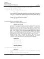
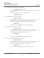
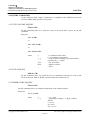
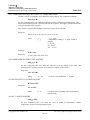
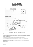
Labkotec Oy
Myllyhaantie 6
FI-33960 PIRKKALA
Tel. +358 29 006 260
Fax +358 29 006 1260
E-mail: [email protected]
Internet: www.labkotec.fi
01.04.2010
D30579De
LabkoMax®
MPS-4 Level Interface
7100 series LabkoMax and LabkoFlex probes
INSTALLATION AND
OPERATING INSTRUCTIONS
Copyright © 2010 Labkotec Oy
We reserve rights for changes without notice
LabkoMax®
MPS-4 Level Interface
7100 series LabkoMax ja LabkoFlex probes
Installation and operating instructions
D30579De
CONTENTS
1. GENERAL ________________________________________________________________________ 3
1.1 LABKOMAX LEVEL MEASUREMENT SYSTEM ____________________________________ 3
1.2 TECHNICAL SPECIFICATIONS ___________________________________________________ 4
2. INSTALLATION __________________________________________________________________ 5
2.1 INSTALLATION OF THE 7100 SERIES LabkoMax PROBE ____________________________ 5
2.3 CABLING _______________________________________________________________________ 8
3. MPS-4 CONFIGURATION AND SETTINGS _________________________________________ 11
3.1 COMMUNICATION SETTINGS ___________________________________________________ 11
3.1.1 BAUDRATE SETTINGS _______________________________________________________________ 11
3.1.2 RS-232/RS-485 SETTINGS _____________________________________________________________ 12
3.3 SETUP COMMANDS ____________________________________________________________ 14
3.3.1 SETTING THE WIRE SPEED ___________________________________________________________
3.3.2 PROBE TYPE SETTING _______________________________________________________________
3.3.3 SETTING THE LEVEL MEASUREMENT _________________________________________________
3.3.4 SETTING THE MINIMUM PRODUCT LEVEL _____________________________________________
3.3.5 NUMBER OF FLOATS SETTING________________________________________________________
3.3.6 SETTING THE MINIMUM FLOAT DISTANCE ____________________________________________
3.3.7 SETTING THE WATER FLOAT OFFSET _________________________________________________
3.3.8 SETTING THE MINIMUM WATER LEVEL _______________________________________________
3.3.9 SETTING THE FLOAT TYPE ___________________________________________________________
3.3.10 SELECTING THE RESULT MODE _____________________________________________________
3.3.11 SETTING THE VOLUME OF THE TANK ________________________________________________
3.3.12 SETTING THE DIAMETER OF THE TANK ______________________________________________
3.3.13 ERASING THE CONVERSION TABLE __________________________________________________
3.3.14 FILLING IN THE CONVERSION TABLE ________________________________________________
3.3.15 READING THE CONVERSION TABLE _________________________________________________
3.3.16 SETTING THE NUMBER OF POINTS IN THE CONVERSION TABLE ________________________
3.3.17 CORRECTING CONVERSION TABLE POINT ____________________________________________
3.3.18 SETTING THE LOW LEVEL ALARM ___________________________________________________
3.3.19 SETTING THE HIGH LEVEL ALARM __________________________________________________
3.3.20 SETTING THE CONDENSEDWATER ALARM ___________________________________________
3.3.21 READING PARAMETER VALUES _____________________________________________________
15
15
16
16
16
17
17
18
18
19
19
19
20
20
20
21
22
22
22
22
23
4. INQUIRY COMMANDS ___________________________________________________________ 24
4.1 LEVEL/VOLUME INQUIRY _____________________________________________________________
4.2 LEVEL INQUIRY ______________________________________________________________________
4.3 TEMPERATURE INQUIRY ______________________________________________________________
4.3.1 TEMPERATURE INQUIRY FOR FIVE TEMPERATURES ___________________________________
4.4 CONDENSED WATER LEVEL INQUIRY __________________________________________________
4.5 WATER LEVEL/VOLUME INQUIRY ______________________________________________________
4.6 ALL VALUES INQUIRY ________________________________________________________________
24
24
24
25
25
25
25
5. ADDITIONAL INQUIRY COMMANDS _____________________________________________ 26
5.1 PROBE STATUS INQUIRY ______________________________________________________________ 26
6. MAINTENANCE _________________________________________________________________ 27
6.1 HARDWARE FAULTS __________________________________________________________________ 27
6.2 MEASURING FAULTS__________________________________________________________________ 27
Copyright © 2010 Labkotec Oy
We reserve rights for changes without notice
Page 2
LabkoMax®
MPS-4 Level Interface
7100 series LabkoMax ja LabkoFlex probes
Installation and operating instructions
D30579De
1. GENERAL
1.1 LABKOMAX LEVEL MEASUREMENT SYSTEM
The LabkoMax level measurement system contains the following devices and software:
7100 series magnetostrictive LabkoMax and LabkoFlex level probes
MPS-4 level interface (power supplies and Ex-barriers)
MD-1 Current loop / RS-232 converter
ME-3 Display unit
LabkoMonitor 8 Fuel tank monitoring software
Fig. 1. LabkoMax measurement system alternatives.
Additional information can be found in following documents:
LabkoFLex
Installation and handling procedure (Doc. No. D30660)
MD-1
Current loop / RS-232 converter, installation and operating
instructions (Doc. No. D30165)
ME-3
Installation and user manual (Doc. No. D30013)
Labcom 800
Operating and Installation Instruction (Doc. No. D04063)
LabkoMonitor 8
Installation and Operating Instructions (Doc. No. D30643)
LabkoMax Configurator
Installation program Installation and Operating Instructions (Doc No D30640)
LabkoNet
www.labkonet.com
Copyright © 2010 Labkotec Oy
We reserve rights for changes without notice
Page 3
LabkoMax®
MPS-4 Level Interface
7100 series LabkoMax ja LabkoFlex probes
Installation and operating instructions
D30579De
1.2 TECHNICAL SPECIFICATIONS
LabkoMax MPS-4 Level Interface
Number of probes:
Output values:
Output format:
Level resolution:
Level linearity:
Volume resolution:
Water level resolution:
Temperature resolution:
Temperature accuracy:
Configuration:
Power supply:
Operation temperature range:
Enclosure protection class:
Dimensions:
Ex-classification:
1…4 pcs 7100 series LabkoMax or LabkoFlex probes
Procuct level, product volume, water level, water
volume and temperature
Digital serial communication in 20 mA current loop
using LABKO ILS protocol, 300...4800 baud.
Optional RS-485 MODBUS
0,1 mm
±0,01% FS tai ±0,25 mm (whichever is greater)
0,1 l
0,1 mm
0,01°C
±0,3°C (-20 … +65°C)
With code switches and through the serial port with
Windows based LabkoMax Configurator Installation
program
230 (±10%) VAC, 50/60 Hz, 4,5VA
-20 … +50°C
IP65
250 x 175 x 75 mm
II (1) G [Ex ia] II B
VTT 03 ATEX 079X
Special conditions: Ta = -25°C … +50°C
Io = 117 mA Po = 883 mW
Output values
IIB: Uo = 30 V
Co = 320 nF Lo = 5 mH
Lo/Ro = 159µH/Ω
Linear output. See chapter 2.3
To probes: shielded twisted pair, max. length 600 m.
Cabling requirements:
To host: instrument cable 1x(2+1)x0,5 mm2, max.
length 400 m.
Isolated serial communication converter
Options:
RS-232/485, 300…19200 Bd
EMC:
Immunity EN 50082-1
EN 50082-2
Emission EN 50081-1
AAA(006) B CCC DD EE F
Year of manufacture:
See serial number from the type
where EE = year of manufacture (e.g. 10 = 2010)
plate
Copyright © 2010 Labkotec Oy
We reserve rights for changes without notice
Page 4
LabkoMax®
MPS-4 Level Interface
7100 series LabkoMax ja LabkoFlex probes
Installation and operating instructions
D30579De
2. INSTALLATION
This manual describes the installation of the 7100 series LabkoMax probe and the MPS-4
level interface unit. LabkoFlex probe is provided in it’s own installation manual (see page
3).
Installation instructions for the ME-3 display unit MD-1 current loop / RS-232 converter,
and LabkoMonitor 8 monitoring software are provided in their own manuals (see page 3).
2.1 INSTALLATION OF THE 7100 SERIES LabkoMax PROBE
The probe must be installed to 2”, 3” or 4” riser pipe. For installation, there must be a
welded sleeve fitted with R2”, R3” or R4” internal thread on the top of the tank.
Recommended riser pipe length is 550 mm.
Fig. 2. Riser pipe
Example of determining riser pipe length
Height measured from
bottom of the tank to
manhole cover in mm
Total length of the probe
in mm
Minimum riser pipe length in mm.
1700
2080 (82”)
480
2100
2490 (98”)
490
2600
3000 (118”)
500
Copyright © 2010 Labkotec Oy
We reserve rights for changes without notice
Page 5
LabkoMax®
MPS-4 Level Interface
7100 series LabkoMax ja LabkoFlex probes
Installation and operating instructions
D30579De
In the above table it is taken into account that here must be at least 100 mm between top
of probe to riser pipe’s top flange.
Total length of the probe in the above table is the length that must be used when ordering
the probe. Values indicated in the table are standard lengths available in the stock.
Before installation, write down the wire speed of the measurement signal of each probe.
The wire speed is located in the label at the probe head, for instance WS: 9.064
uSEC/INCH.
Cable gland
Fig. 3. Installation of the probe.
The installation is carried out as follows:
-
install the riser pipe to the tank.
-
install probe spacers, probe grounding ring, floats, protecting sleeve, probe
foot fastening adapter and probe foot to the probe. Product float must be
above the water float. With 2” steel floats product float and water float are
identical, but there is metal collar above the water float to add weight, and
second collar under the water float to prevent lowering the water float under
the probe’s measuring range. 3” and 4” polyurethane water floats have
ballast plate on bottom. Insure that you are using a proper water float: for
gasoline there is stamped 85 on the ballast plate and for diesel there is 95.
-
screw the connection cable to the probe
-
slide the floats to the bottom of the probe shaft. Note: The product float
must be above water float. Insert the probe in the riser pipe and lower it to
the bottom of the tank.
Copyright © 2010 Labkotec Oy
We reserve rights for changes without notice
Page 6
LabkoMax®
MPS-4 Level Interface
7100 series LabkoMax ja LabkoFlex probes
Installation and operating instructions
D30579De
-
insert the cable through the gland on the riser pipe cap, attach the grounding
wire to the grounding ring of the probe and to the riser pipe cap
-
attach the cap and the cap’s grounding wire
-
tighten the cable gland and connect the cable to the junction box.
Fig. 4. Connecting probe to the junction box.
Junction box is normally connected to the system’s equipotential ground via mounting
plate and riser pipe’s cover flange, but if this not the case, then junction box must be
connected to the equipotential ground with at least 4 mm2 wire.
When installing the probe in an underground tank the following facts shall be taken into
account:
- the space above the entry must be free to allow the installation and service of
the probe (it must be possible to lift up the probe from the tank)
- the installation shaft shall be sufficiently large (diameter ≥1 m) to allow the
installation and connection of the probe
Copyright © 2010 Labkotec Oy
We reserve rights for changes without notice
Page 7
LabkoMax®
MPS-4 Level Interface
7100 series LabkoMax ja LabkoFlex probes
Installation and operating instructions
D30579De
2.2 INSTALLATION OF THE MPS-4 LEVEL INTERFACE UNIT
The MPS-4 must always be installed in the non-hazardous area. The protection class of
the unit’s enclosure (dust tight and jet proof to IP 65) must be taken into account. The
MPS-4 can be mounted permanently on wall or in a device cabinet in the field, for
example.
The unit is fastened with four screws through the holes in the corners of the housing.
Mounting dimensions 235 x 160 mm.
Fig. 5. MPS-4 mounting dimensions.
2.3 CABLING
NOTE! MPS-4 control unit must not be installed in explosion-hazardous zone.
However, it is allowed to install the 7100-probe in explosion-hazardous zone
(0/1/2). When doing so, the following standards need to be followed; EN 50039
Electrical apparatus for potentially explosive atmospheres – Intrinsically safe
electrical systems “I”, EN 60079-14 Electrical apparatus for explosive gas
atmospheres. Part 14: Electrical installation in hazardous areas.
The table below shows the maximum combined capacitance and inductance values for
explosion group IIB for the MPS-4 control unit. For group IIA, values for IIb can be
applied.
IIB
Co
Lo
320 nF
0,15 mH
240 nF
1 mH
210 nF
2 mH
180 nF
5 mH
Copyright © 2010 Labkotec Oy
We reserve rights for changes without notice
Page 8
LabkoMax®
MPS-4 Level Interface
7100 series LabkoMax ja LabkoFlex probes
Installation and operating instructions
D30579De
A shielded 2-conductor cable must be used between the MPS-4 unit and the probe. When
cable conductors have at least 0.5 mm2 cross section, maximum cable length is 600
meters if capacitance and inductance values are within allowed limits.
To
equipotential
ground
Fig. 6. Connection between the MPS-4 and the 7100 probe.
The cable between the 7100 probe and the MPS-4 level interface unit is connected as
shown in the figure 6. The cable shield is connected to terminal 3 in the junction box. At
the MPS-4 end of the cable the shield is not connected and it must be isolated (for
example by insulating tape).
The riser pipe and all other metal parts must be connected to the system’s equipotential
ground by conductor having at least 4 mm2 cross section.
The mains supply to the MPS-4 (230 Vac) is connected to the terminals marked L1, N
and PE.
MPS-4 units mains supply lines must be equipped with decoupling switch (250Vac/1A)
to ease use and maintenance. This switch must be located near the MPS-4 unit and must
be labeled as unit’s decoupling switch.
All connections should be appropriately made and checked before connecting mains
supply.
For the current loop cabling between the MPS-4 level interface units and the host unit
(such as ME-3), it is recommended to use a 2-conductor shielded cable with a minimum
Copyright © 2010 Labkotec Oy
We reserve rights for changes without notice
Page 9
LabkoMax®
MPS-4 Level Interface
7100 series LabkoMax ja LabkoFlex probes
Installation and operating instructions
D30579De
conductor area of 0.5 mm2. When using this type of cable, the total current loop length
can be up to 400 m.
The current loop from the MPS-4 to the host unit is connected to CL+ and CL- terminals
on the LINE connection. The cable shield is connected to the terminal 1. This potential
free terminal is designed to be used as an extension terminal for the shields of the cables
of series connected MPS-4 units. When using several MPS-4 units, the current loop
connections (LINE) of these units are connected in series.
Fig. 7. Connecting several MPS-4 units in series.
The digital 20 mA current loop of the MPS-4 can be converted into an RS-232 serial
interface using the RS-232/485 adapter card for MPS-4. The RS-232 interface is needed
when using the LabkoMonitor 8 software or connecting the MPS-4 to a modem or POS.
Fig. 8. MPS-4 RS-232 interface using optional RS-232/485 adapter card.
When connecting multiple MPS-4 units to a host controller with RS-232 communication,
the units are connected in series with current loop and converted to RS-232 using MD-1
converter. See the MD-1 manual for additional information.
Copyright © 2010 Labkotec Oy
We reserve rights for changes without notice
Page 10
LabkoMax®
MPS-4 Level Interface
7100 series LabkoMax ja LabkoFlex probes
Installation and operating instructions
D30579De
3. MPS-4 CONFIGURATION AND SETTINGS
The configuration of the MPS-4 is done with three rotary switches and with ASCII
commands using the serial communication port of the MPS-4.
The rotary switches are located in upper left corner of the circuit card. The settings from
these switches are detected only on powering up the MPS-4, so if the settings are changed
the power supply for the MPS-4 must be reconnected or the RESET button must be
pressed.
1 2 3 4
Fig. 9. MPS-4 configuration switches at the upper left corner of the circuit board.
The six switches (S4...S9) behind the current loop terminals (CL+, CL-) must all be in the
right hand position.
Measurement settings are made using computer (PC) with RS-232 communication port. If
MPS-4 unit is not equipped with RS-232/485 adapter card, then digital current loop/RS232 converter MD-1 (or equivalent) must be used. If MPS-4 unit is connected to ME-3
display unit, then settings can be made through the RS-232 port of the ME-3.
Settings can be made with LabkoMax Configurator program (Windows) or Windows
Hyperterminal.
3.1 COMMUNICATION SETTINGS
3.1.1 BAUDRATE SETTINGS
The communication speed of the MPS-4 serial port is selected with switch S3. The
settings are:
switch position
communication speed
0
300 bd (default, used with ME-3)
1
1200 bd
2
2400 bd (default with Labcom 800)
3
4800 bd
4
9600 bd (RS232/485 only)
5
19200 bd (RS232/485 only)
The other communication parameters are: 8 data bits, 1 stop bit, no parity.
Copyright © 2010 Labkotec Oy
We reserve rights for changes without notice
Page 11
LabkoMax®
MPS-4 Level Interface
7100 series LabkoMax ja LabkoFlex probes
Installation and operating instructions
D30579De
3.1.2 RS-232/RS-485 SETTINGS
Fig. 10. LabkoMax MPS-4 adapter, switch positions
If there are multiple MPS-4 units connected to the same RS-485 line, then
termination resistor must be activated only in the unit at the end of the line.
Copyright © 2010 Labkotec Oy
We reserve rights for changes without notice
Page 12
LabkoMax®
MPS-4 Level Interface
7100 series LabkoMax ja LabkoFlex probes
Installation and operating instructions
D30579De
3.2 SETTING THE PROBE IDENTIFICATION NUMBERS
In this system each probe has it’s own identification number. The number range is from
01 to 99. There are four connectors for probes (PROBE 1,2,3,4) in the MPS-4. The
number of the first probe (PROBE 1) is set by two rotary switches. The rest three probes
are automatically numbered in ascending order (number of the previous probe plus one).
For instance, if the number of the first probe is set to 01, then PROBE 2 is 02, PROBE 3
is 03 and PROBE 4 is 04.
Fig. 11. Rotary switches S1, S2 and S3.
If there is no probe connected to a probe connector, that number is still reserved. PROBE
1 terminals are 11 and 12 (left hand side on the circuit board), PROBE 2 terminals 21
and 22, PROBE 3 terminals 31 and 32, PROBE 4 terminals 41 and 42.
If two MPS-4 units are used then identification numbers must be set so that number
ranges do not overlap. Example: If first unit’s identification number rotary switches are
set to 01, then second unit’s rotary switches must be set to 05 or higher.
Copyright © 2010 Labkotec Oy
We reserve rights for changes without notice
Page 13
LabkoMax®
MPS-4 Level Interface
7100 series LabkoMax ja LabkoFlex probes
Installation and operating instructions
D30579De
3.3 SETUP COMMANDS
The most important setup commands of the MPS-4 interface are explained below.
Commands can be given with Windows based LabkoMax Configurator software or by
means of PC’s communication program.
The settings for the communication between PC and MPS-4 are: baud rate (the same as
set to MPS-4), 8 data bits, 1 stop bit, no parity.
Using the setup commands requires that a serial RS-232 interface is available for the
MPS-4. Such an interface is incorporated in the RS232/485 adapter for MPS-4, MD-1 and
ME-3 units, for example.
At the startup there must be at least the following two settings made correctly:
- Setting the wire speed of the measurement signal (3.3.1).
- Probe type setting (3.3.2).
- Setting the level measurement (3.3.3).
Notice: Setting the wire speed must be carried out before any other settings.
Because the product float cannot mechanically descent to position corresponding zero
level measured from the bottom of the tank, it is useful to specify minimum level value
under which level is always interpreted to be zero. This minimum level value is set by:
- Setting the minimum product level (3.3.4).
Number of floats setting:
- Number of floats setting (3.3.5)
If the product float and the water float touch each other and do not float freely, level
measurement is not accurate. Therefore minimum float distance is specified by:
- Setting the minimum float distance (3.3.6).
Reading of probe status (5.1) can be used to ensure the floats are not closer to each other
than specified by minimum float distance.
To be accurate, water bottom measurement requires:
-Setting the water float offset (3.3.7).
As with the product float, the water float can not descent to zero level measured from the
bottom of the tank either, and following setting is needed:
- Setting the minimum water level (3.3.8).
Some settings are dependant of the float type and therefore following setting can be used
to check these settings:
- Setting the float type (3.3.9)
Method of calculation of the volume of the product is specified by:
- Setting the result mode (3.3.10).
If result mode is set to zero, then no additional settings are needed to calculate volume
because level/volume inquiry returns level of the product. If result mode is set to one,
then following settings must carried out:
- Setting the volume of the tank (3.3.11).
- Setting the diameter of the tank (3.3.12).
Copyright © 2010 Labkotec Oy
We reserve rights for changes without notice
Page 14
LabkoMax®
MPS-4 Level Interface
7100 series LabkoMax ja LabkoFlex probes
Installation and operating instructions
D30579De
If result mode is two, the user specified conversion table is used. Following commands
are used to set the conversion table:
- Erasing the conversion table (3.3.13).
- Filling in the conversion table (3.3.14).
Conversion table can be displayed by read conversion table command (3.3.15). To
make corrections to already filled conversion table, following commands are useful:
- Setting the number of points in the conversion table (3.3.16).
- Correct conversion table point (3.3.17).
Level and volume inquiries contain status of the limits which are set by following
commands:
- Setting the low level alarm (3.3.18).
- Setting the high level alarm (3.3.19).
- Setting the condensed water alarm (3.3.20).
Setting can be displayed by read parameters command (3.3.21).
All commands are made up of two characters, a two-digit probe number and a parameter,
if any. The command is ended by pressing the ENTER key (RETURN, carriage return).
The probe number is used to address the command to the desired probe.
In the command instructions the following markings are used:
n1n2
probe number (01...99)
<CR>
carriage return (RETURN, ENTER)
The MPS-4 responds to all setup commands executed and acknowledged using two
characters: #<CR>.
3.3.1 SETTING THE WIRE SPEED
$Yn1n2x1...x4<CR>
Each probe has its own speed of wire value. The speed of wire is marked on the label on
probe head. This value is given as an integer in the place of x1...x4 for the probe in
question, for instance the wire speed 9.034 µs/inch for the probe 01 is given as
$Y019034<CR>.
This value is shown as WireSpeed in the output of the RP command.
3.3.2 PROBE TYPE SETTING
PTnnt,
where nn is probe number (01,...,99) and t (1,...,6) is probe type.
Types 1,4
0"< probe length <=216"
Types 2,5 216"< probe length <=288"
Types 3,6 288"< probe length
Probe types 1, 2 and 3 have 5 thermistor probes (R5 designation in part number).
Probe types 4, 5 and 6 have 1 thermistor probes (R1 designation in part number).
Default value for probe type is 4.
Copyright © 2010 Labkotec Oy
We reserve rights for changes without notice
Page 15
LabkoMax®
MPS-4 Level Interface
7100 series LabkoMax ja LabkoFlex probes
Installation and operating instructions
D30579De
3.3.3 SETTING THE LEVEL MEASUREMENT
$Zn1n2m1...m4<CR>
This command is used to calibrate the level readout to correspond to the actual level
measured by a gauge stick from the bottom of the tank. The measured value is given as
parameter m1...m4 in millimetres.
The level of the product must be at least 200 mm to execute the level setting command.
Example. If the level is measured to be 1557 mm in the tank with probe’s identification
number 01, then following command is given:
$Z011557<CR>
3.3.4 SETTING THE MINIMUM PRODUCT LEVEL
LMn1n2m1...m4<CR>
This parameter is given as tenths of millimetre and specifies level under which level is
displayed as zero. Because the product float cannot descent to position corresponding
zero level measured from the bottom of the tank, there is minimum level under which
level can not be measured. Because the product float is above the water float minimum
level must be at least height of the water float added by sinking depth of the product float.
If 2” steel floats are used, then collars above and under the water float must be taken into
account. In the table collars are assumed to be 10 mm high. Following table contains
minimum level measured from the bottom of the tank for different floats. Values in the
table are based on measurement which were made with the floats and various liquids.
Because actual conditions can differ from measurement conditions, more accurate values
can be determined when measurements are made in real operating environment.
Float type
Minimum level in mm from the
bottom of the tank that can be
measured
Parameter value with the setting
command
2” steel
149
1490
2” nitrophyl
176
1760
3” polyureth.
82
820
4” polyureth.
79
790
Example. Probe with identification number 01 is equipped with 3” floats. Minimum level
is set to 82.0 mm using following command:
LM01820<CR>
This value is shown as MinLevel in the output of the RP command.
3.3.5 NUMBER OF FLOATS SETTING
FCnnk,
where nn is probe number (01,...,99) and k (1,2) is number of floats.
Default value is 2.
Copyright © 2010 Labkotec Oy
We reserve rights for changes without notice
Page 16
LabkoMax®
MPS-4 Level Interface
7100 series LabkoMax ja LabkoFlex probes
Installation and operating instructions
D30579De
3.3.6 SETTING THE MINIMUM FLOAT DISTANCE
MDn1n2m1...m4<CR>
Minimum float distance which is given in tenths of millimetre specifies how close to each
other floats can be without causing errors to measurement. Because the probe measures
position of the magnets attached to the floats, this parameter means minimum distance of
the magnets. With 2” steel floats weighting collar above the water float must be taken
into account and in the following table it is assumed to be 10 mm high.
Float type
Minimum distance in mm
Parameter value with the setting
command
2 “ steel
86
860
2” nitrophyl
78
780
3” polyureth.
65
650
4” polyureth.
71
710
Example. Probe with identification number 01 is equipped with 3” floats. Minimum
distance is set to 65.0 mm using following command:
MD01650<CR>
This value is shown as MinFloatDist in the output of the RP command.
3.3.7 SETTING THE WATER FLOAT OFFSET
FDn1n2m1...m4<CR>
The water float offset, which given in tenths of millimetre, is used to correct the
difference in floating depths of the product float and the water float. Given value is added
to the measured water level. A positive value must be given if measured water level is
lower than the actual water level.
Float
Difference in floating depths in
mm
Parameter value with the setting
command
gasoline
diesel
gasoline
diesel
2 “ steel
-3
-13
-30
-130
2” nitrophyl
-70
-62
-700
-620
3” polyureth.
3
11
30
110
4” polyureth.
-6
3
-60
30
Notice: Values in the above table are only approximate. More accurate values can be
acquired by measuring floating depths in actual situation.
Example. Probe 01 is equipped with 3” floats. Water float offset is set to 11.0 mm by
following command:
FD01110<CR>
This value is shown as WfOffset in the output of the RP command.
Copyright © 2010 Labkotec Oy
We reserve rights for changes without notice
Page 17
LabkoMax®
MPS-4 Level Interface
7100 series LabkoMax ja LabkoFlex probes
Installation and operating instructions
D30579De
3.3.8 SETTING THE MINIMUM WATER LEVEL
WMn1n2m1...m4<CR>
This parameter which given in tenths of millimetre is needed because, as with the product
float, the water float can not descent zero level measured from the bottom of the tank.
Water levels below this value are displayed as zero.
NOTE! The values mentioned in the table below are only estimates. The actual setting
should be done as follows.
1. Set the value of minimum water level first to a value of 0 mm.
2. Check the value of condensed water level with command $G (chapter 4.4).
3. Set the minimum water value to a value which is 2 mm higher than just checked.
4. Check the condensed water level again. It should now be 0 mm.
Float
Minimum water level in mm
Parameter value with the setting
command
gasoline
diesel
gasoline
diesel
2 “ steel
74
64
740
640
2” nitrophyl
30
38
300
380
3” polyureth.
18
26
180
260
4” polyureth.
6
15
60
150
Example. Probe 01 is equipped with 3” floats and measures level gasoline level.
Minimum water level is set to 18.0 mm by following command:
WMn1n2m1...m4<CR>
This value is shown as MinWater in the output of the RP command.
3.3.9 SETTING THE FLOAT TYPE
FTn1n2x<CR>
This command is used to set the type of the floats for each probe. This setting is given for
the product float/water float pair. For specific size, product floats are the same for
gasoline and diesel, but water floats have different weights. The values of x for each float
type are listed below:
x
type of the float
1
2” stainless for gasoline
2
2” stainless for diesel
3
3” polyurethane for gasoline
4
3” polyurethane for diesel
5
4” polyurethane for gasoline
6
4” polyurethane for diesel
Copyright © 2010 Labkotec Oy
We reserve rights for changes without notice
Page 18
LabkoMax®
MPS-4 Level Interface
7100 series LabkoMax ja LabkoFlex probes
Installation and operating instructions
D30579De
7
2” nitrophyl for gasoline
8
2” nitrophyl for diesel
Example. Probe 01 measures gasoline level and is equipped with 3” polyurethane floats.
Float type is configured by:
FT013<CR>
This value is shown as FloatType in the output of the RP command.
3.3.10 SELECTING THE RESULT MODE
$Dn1n2x<CR>
By the $V and $A inquiry commands the level measured can be sent in three different
modes depending on the parameter x stored in the memory as follows:
x=0
x=1
x=2
result in millimetres
result in litres, calculated using the built-in level-to-volume table
for a horizontal, cylindrical tank
result according to the values stored in the conversion table
Example. Probe 01 is configured to calculate volume using the built-in level-to-volume
table for a horizontal, cylindrical tank by following command:
$D011<CR>
This value is shown as ResultMode in the output of the RP command.
3.3.11 SETTING THE VOLUME OF THE TANK
(This setting is needed only when result mode is set to 1.)
$Qn1n2l1...l6<CR>
When using the built-in level-to-volume table (result mode = 1), this command is used to
save the volume of a horizontal, cylindrical tank in litres (l1...l6).
Example: Probe 01 installed in tank which has 22000 l
configured by:
nominal volume. This is
$Q0122000<CR>
This value is shown as NomVolume in the output of the RP command.
3.3.12 SETTING THE DIAMETER OF THE TANK
(This setting is needed only when result mode is set to 1.)
$Rn1n2m1...m4<CR>
When using the built-in level-to-volume table (result mode = 1), this command is used to
save the diameter of a horizontal, cylindrical tank in millimetres m1...m4.
Example. Probe 01 is in a tank with 1850 mm diameter. This is set by:
$R011850<CR>
Copyright © 2010 Labkotec Oy
We reserve rights for changes without notice
Page 19
LabkoMax®
MPS-4 Level Interface
7100 series LabkoMax ja LabkoFlex probes
Installation and operating instructions
D30579De
This value is shown as Diameter in the output of the RP command.
3.3.13 ERASING THE CONVERSION TABLE
(This setting is used when result mode is set to 2.)
$En1n2<CR>
This command as all commands affecting the user given conversion table are used only if
result mode 2 is selected. Before starting to store new pairs of values in the table, the
table pointer must be set to its initial value using this command. (This is thus done only
once before programming all 2...32 points in the table).
Example. Erase conversion table used by probe 01:
$E01<CR>
3.3.14 FILLING IN THE CONVERSION TABLE
(This setting is used when result mode is set to 2.)
$Fn1n2m1...m4/l1...l6<CR>
Conversions of units and level-to-volume can be made by setting in the conversion table
the desired m1...m4 readings in millimetres and the corresponding l1...l6 values in the
desired units. The result to be sent using the $V inquiry command is calculated linearly
between these set points, when the corresponding result mode has been selected. Filling
in the table must be started from the lowest level. It is recommended to set 0/0 as the first
point. The m1...m4 and l1...l6 values shall always be higher than those of the previous
point. At least two points must be stored; the max. number of these freely selectable
points is 32. When storing the points, the current level has no significance. The difference
between successive volume readings must not exceed 65000. If the level exceeds the
highest table point the volume value is extrapolated using the two highest table point.
Example: Probe 01 volume is calculated with conversion table where 450 mm
corresponds to 2000 l, 900 mm to 6000 l, 1350 mm to 13000 l and 1700 mm level
corresponds 19500 l volume. This table is configured by following commands:
$F010/0<CR>
$F01450/2000<CR>
$F01900/6000<CR>
$F011350/13000<CR>
$F011700/19500<CR>
3.3.15 READING THE CONVERSION TABLE
RTn1n2<CR>
This command displays the points stored in the conversion table (level/corresponding
reading).
Example of displayed data (5 points stored in the table):
Copyright © 2010 Labkotec Oy
We reserve rights for changes without notice
Page 20
LabkoMax®
MPS-4 Level Interface
7100 series LabkoMax ja LabkoFlex probes
Installation and operating instructions
D30579De
0 0<CR>
450 2000<CR>
900 6000<CR>
1350 13000<CR>
1700 19500#<CR>
3.3.16 SETTING THE NUMBER OF POINTS IN THE CONVERSION TABLE
SXn1n2x<CR>
This command sets the number of the points (0…32) in the conversion table and it is used
only in special cases when the configured table needs editing.
When the table points are filled, the point count number is automatically incremented.
With this command the number of points which are taken into account can be reduced.
Example. In the previous example of filling the conversion table, five points were given.
Point count can be set to 3 with following command:
SX013<CR>
And points 4 and 5 can be given again with new values:
$F011350/14000<CR>
$F011800/19500<CR>
Points 4 and 5 can be corrected also by using following command.
Copyright © 2010 Labkotec Oy
We reserve rights for changes without notice
Page 21
LabkoMax®
MPS-4 Level Interface
7100 series LabkoMax ja LabkoFlex probes
Installation and operating instructions
D30579De
3.3.17 CORRECTING CONVERSION TABLE POINT
CTn1n2p1p2m1...m4/l1...l6<CR>
This command is used to correct values in the conversion table. Number of the point to
correct p1p2 (01…32).
Example. Correcting point 02 in probe 01 conversion table:
CT0102450/2100<CR>
3.3.18 SETTING THE LOW LEVEL ALARM
$Ln1n2m1...m4<CR>
This command is used to set the low level alarm to the desired level m1...m4 in
millimetres. This setting is necessary only if required by the central unit used.
Example. Alarm level for probe 01 is set to 300 mm by following command:
$L01300<CR>
This value is shown as LlvlAlarm in the output of the RP command.
3.3.19 SETTING THE HIGH LEVEL ALARM
$Hn1n2m1...m4<CR>
This command is used to set the high level alarm to the desired level m1...m4 in
millimetres. This setting is necessary only if required by the central unit used.
Example. High level alarm for probe 01 is set 1820 mm:
$H011820<CR>
This value is shown as HlvlAlarm in the output of the RP command.
3.3.20 SETTING THE CONDENSEDWATER ALARM
$Wn1n2m1...m4<CR>
This command is used to set the water bottom alarm to the desired level m1...m4 in
millimetres. This setting is necessary only if required by the central unit used.
Example: Water bottom alarm for probe 01 is set to 30 mm:
$W0130<CR>
This value is shown as WaterAlarm in the output of the RP command.
Copyright © 2010 Labkotec Oy
We reserve rights for changes without notice
Page 22
LabkoMax®
MPS-4 Level Interface
7100 series LabkoMax ja LabkoFlex probes
Installation and operating instructions
D30579De
3.3.21 READING PARAMETER VALUES
RPn1n2<CR>
This command displays the names of the parameters and their values.
Example. Response to
RP command
WireSpeed = 9.034
Offset = -16.49
WfOffset = 11.0
MinLevel = 82.0
MinWater = 18.0
MinFloatDist = 65.0
FloatType = 3
LevelTC = 30
WaterTC = 30
TempTC = 60
ResultMode = 2
Diameter = 1850
NomVolume = 22000
LlvlAlarm = 300
HlvlAlarm = 1820
WaterAlarm = 30
TablePoints = 5 #
Wire speed (3.3.1) of the probe’s measuring signal.
This value is calculated when level measurement is set (3.3.3).
Water float offset = 11.0 mm (3.3.7).
Minimum level = 82.0 mm (3.3.4).
Minimum water level = 18.0 mm (3.3.8).
Minimum float distance = 65.0 mm (3.3.6).
Float type (3.3.9).
Filter coefficient for level measurement (factory setting).
Filter coefficient for water level measurement (factory setting).
Filter coefficient for temperature measurement (factory setting).
Result mode (3.3.10).
Tank diameter = 1850 mm (3.3.12).
Tank volume = 22000 l (3.3.11).
Low level alarm limit = 300 mm (3.3.18).
High level alarm limit = 1820 mm (3.3.19).
Water bottom alarm limit = 30 mm (3.3.20).
Number of points in the conversion table (3.3.13 – 3.3.16).
All rows end with <CR>.
Copyright © 2010 Labkotec Oy
We reserve rights for changes without notice
Page 23
LabkoMax®
MPS-4 Level Interface
7100 series LabkoMax ja LabkoFlex probes
Installation and operating instructions
D30579De
4. INQUIRY COMMANDS
All the following basic inquiry commands are compatible with LABKO ILS protocol
used in LABKO 2000 capacitive level probes.
4.1 LEVEL/VOLUME INQUIRY
$Vn1n2<CR>
By this command probe n1n2 sends the result in the mode that is preset by the $D
command.
Response:
#xl1...l6<CR>
or
#xl1...l6_LLA<CR>
or
#xl1...l6_HLA<CR>
where
x
1 = condensed water alarm
0 = no condensed water alarm
= result in units according to preset parameters
(result mode), 1...6 digits
= low level alarm
= high level alarm
= space
l1...l6
LLA
HLA
_
4.2 LEVEL INQUIRY
$Mn1n2<CR>
By this command probe n1n2 sends the level in millimetres (irrespective of the result
mode) in the same mode as the $V command when the result mode is 0.
4.3 TEMPERATURE INQUIRY
$Tn1n2<CR>
By this command probe n1n2 sends the temperature of the measured liquid.
Response:
#+/-t1...t3<CR>
where
+/t1...t3
= + or - sign
= temperature reading, 1...3 digits, scaled as
follows:
6 = 0.6°C
84 = 8.4°C
237 = 23.7°C
Copyright © 2010 Labkotec Oy
We reserve rights for changes without notice
Page 24
LabkoMax®
MPS-4 Level Interface
7100 series LabkoMax ja LabkoFlex probes
Installation and operating instructions
D30579De
4.3.1 TEMPERATURE INQUIRY FOR FIVE TEMPERATURES
Certain versions of LabkoMax and LabkoFlex probes support five temperature readings.
TAn1n2<CR>
By this command probe n1n2 sends the readings of all five temperature measurements. The
lowest measurement point is represented first in the response. The highest measurement point
is represented last in the response.
This feature is supported from MPS-4 software version v2.10 onwards.
Response:
#+/-t1...t3 +/-t1...t3 +/-t1...t3 +/-t1...t3 +/-t1...t3
where
+/t1...t3
= + or - sign
= temperature reading, 1...3 digits, scaled as
follows:
6 = 0.6°C
84 = 8.4°C
237 = 23.7°C
Example:
TA01<CR>
Response:
#+229 +229 +230 +229 +232
4.4 CONDENSED WATER LEVEL INQUIRY
$Gn1n2<CR>
By this command probe n1n2 sends the water level on the bottom of the tank. (The
measurement is possible only for non-conductive liquids, such as fuels.)
Response:
#m1...m4<CR>
where
m1...m4
= water level in millimetres, 1...4 digits
4.5 WATER LEVEL/VOLUME INQUIRY
WVn1n2<CR>
Response:
#l1...l6<CR>
where
l1...l6
= result in units according to preset parameters
(result mode)
4.6 ALL VALUES INQUIRY
$An1n2<CR>
By this command probe n1n2 sends the level in tenths of millimetres, volume,
temperature, water level and possible alarms.
Copyright © 2010 Labkotec Oy
We reserve rights for changes without notice
Page 25
LabkoMax®
MPS-4 Level Interface
7100 series LabkoMax ja LabkoFlex probes
Installation and operating instructions
D30579De
Response:
#m1...m5;v1...v6;t1...t4;g1...g4;WHL<CR>
where
;
= field separator (semicolon)
m1...m5
= level as an integer in tenths of mm (1...5 digits)
v1...v6
= level/volume according to result mode (1...6
digits)
t1...t4
= temperature as an integer in tenths of °C(t1 can
also be a minus sign, 1...4 characters)
g1...g4
= water level in millimetres (1...4 digits)
W
= condensed water alarm
H
= high level alarm
L
= low level alarm
The contents of the v1...v6 reading is determined by the result mode (set by the $D
command) and indicates either the level in millimetres or the volume in litres.
The alarm flags W, L and H appear in this order and always one after another without
spaces. When an alarm is switched off, it will not be replaced by a space. Example: When
the water bottom and low level alarms are on, the alarm field will be: WL<CR>.
5. ADDITIONAL INQUIRY COMMANDS
5.1 PROBE STATUS INQUIRY
RE n1n2<CR>
Response to this command is probe n1n2 error status.
If there are no errors then response is:
#00<CR>
Non-zero response indicates error type:
01
no probe connected
02
data error
04
low voltage
08
floats are too close to each other
40
probe reading is not yet accurate
80
measurement is not yet performed for the probe
Copyright © 2010 Labkotec Oy
We reserve rights for changes without notice
Page 26
LabkoMax®
MPS-4 Level Interface
7100 series LabkoMax ja LabkoFlex probes
Installation and operating instructions
D30579De
6. MAINTENANCE
6.1 HARDWARE FAULTS
MPS-4 unit’s mains fuse which is located in the lower left corner of the unit (marked
125mAT), can be changed to an other IEC127 50x20mm/125mAT glass tube fuse if
appropriate safety measures are used.
Any other maintenance operations can be carried out only by persons expierenced in Exiinstallations and authorized by Labkotec Oy.
Service, inspection and repair of Ex-apparatus needs
to be done according to standards IEC 60079-17 and
IEC 60079-19.
6.2 MEASURING FAULTS
If measured values are not correct, it would help to solve the problem if following data
from MPS-4 unit is available when contacting the manufacturer:
-
Result of RP command (ref. 3.3.19).
-
Result of RE command (ref. 5.1).
Copyright © 2010 Labkotec Oy
We reserve rights for changes without notice
Page 27