1
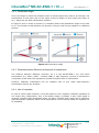
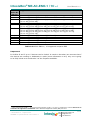
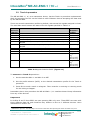
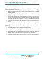
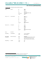
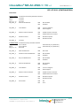
IntesisBox® ME-AC-ENO-1 / 1C v.1 IntesisBox ME-AC-ENO-1 ME-AC-ENO-1C User Manual rev.7 ® v.1.0.9 v.1.0.9 EnOcean Interface for Mitsubishi Electric air conditioners. Compatible with all models of Domestic and Mr. Slim lines of air conditioners commercialised in Europe. User's Manual v1 r7 eng Reference: ME-AC-ENO-1 / 1C Issue Date: 05/2010 This information is subject to change without notice © Intesis Software S.L. - All rights reserved IntesisBox is a registered trademark of Intesis Software SL 1 / 28 URL email tel http://www.intesis.com [email protected] +34 938047134 IntesisBox® ME-AC-ENO-1 / 1C v.1 © Intesis Software S.L. User Manual rev.7 All Rights Reserved. Information in this document is subject to change without notice. The software described in this document is furnished under a license agreement or nondisclosure agreement. The software may be used only in accordance with the terms of those agreements. No part of this publication may be reproduced, stored in a retrieval system or transmitted in any form or any means electronic or mechanical, including photocopying and recording for any purpose other than the purchaser’s personal use without the written permission of Intesis Software S.L. Intesis Software S.L. Milà I Fontanals, 1 bis, 1º 08700 Igualada Spain TRADEMARKS All trademarks and tradenames used in this document are acknowledged to be the copyright of their respective holders This information is subject to change without notice © Intesis Software S.L. - All rights reserved IntesisBox is a registered trademark of Intesis Software SL 2 / 28 URL email tel http://www.intesis.com [email protected] +34 938047134 IntesisBox® ME-AC-ENO-1 / 1C v.1 User Manual rev.7 INDICE 1. Presentation ................................................................................................... 4 1.1. Main Features: ................................................................................................. 4 1.2. Typical Application............................................................................................ 5 2. Connection and placement ................................................................................ 7 2.1. Connection ...................................................................................................... 7 2.2. Placement ....................................................................................................... 8 2.2.1 Screening zones ...................................................................................... 8 2.2.2 Penetration Angle .................................................................................... 9 2.2.3 Distance between Receiver and sources of interference ................................ 9 2.2.4 Use of repeaters ..................................................................................... 9 3. Configuration ................................................................................................ 10 3.1. Learning procedure ........................................................................................ 11 3.2. Teach-in procedure ........................................................................................ 13 3.3. Device deleting procedure ............................................................................... 14 4. Special Behaviours ........................................................................................ 15 4.1. Window contact ............................................................................................. 15 4.2. External temperature Sensors. Virtual temperature ............................................ 15 4.3. Key Card reader ............................................................................................. 16 4.4. Occupancy sensors ......................................................................................... 17 4.5. MultiTeach-in procedure .................................................................................. 17 5. Communications monitoring............................................................................ 18 5.1. AC communication monitoring mode (RED LED) ................................................. 18 5.2. EnOcean communication monitoring mode (GREEN LED) ..................................... 18 6. Technical data and dimensions ........................................................................ 19 7. A.C profile data (Generic HVAC interface) ......................................................... 20 8. AC Unit Types compatibility ............................................................................ 25 9. Error Codes .................................................................................................. 26 10. EnOcean Interoperability ................................................................................ 27 11. Regulations and standards .............................................................................. 28 This information is subject to change without notice © Intesis Software S.L. - All rights reserved IntesisBox is a registered trademark of Intesis Software SL 3 / 28 URL email tel http://www.intesis.com [email protected] +34 938047134 IntesisBox® ME-AC-ENO-1 / 1C v.1 User Manual rev.7 1. Presentation ME-AC-ENO-1 and ME-AC-ENO-1C devices allow a complete and natural integration of Mitsubishi Electric air conditioners with EnOcean control systems both in their 868 MHz (ME-AC-ENO-1) and 315 MHz (ME-AC-ENO-1C) versions. Compatible with all models of Domestic and Mr. Slim lines of air conditioners commercialised in Europe. Other models from different lines are compatible too (check section 8). 1.1. Main Features: Reduced dimensions. Quick installation. External power not required. Direct connection to the Mitsubishi Electric AC indoor unit. Fully EnOcean interoperable. Multiple profiles Control of the AC unit based in the ambient temperature read by the own AC unit, or in the ambient temperature read by any EnOcean thermostat. Total Control and Monitoring of the AC unit from EnOcean, including monitoring of AC unit’s state of internal variables, and error indication and error code. AC unit can be controlled simultaneously by the IR remote control of the AC unit and by EnOcean devices. Implements the newly approved HVAC EEP’s Advanced room control functionalities. Configurable to work as a repeater. This information is subject to change without notice © Intesis Software S.L. - All rights reserved IntesisBox is a registered trademark of Intesis Software SL 4 / 28 URL email tel http://www.intesis.com [email protected] +34 938047134 IntesisBox® ME-AC-ENO-1 / 1C v.1 User Manual rev.7 1.2. Typical Application In Figure 1.1 it is shown a typical application of ME-AC-ENO-1 / 1C in a hotel room. The different devices that control the A.C unit, like switches, Key cards, window contacts, are connected to it through the ME-AC-ENO-1 / 1C. • Enocean standard communication • Small Dimensions • Fast Installation • No external PS • Several Profiles • Direct connection to AC unit Figure 1.1 Typical application of ME-AC-ENO-1 / 1C in a hotel This information is subject to change without notice © Intesis Software S.L. - All rights reserved IntesisBox is a registered trademark of Intesis Software SL 5 / 28 URL email tel http://www.intesis.com [email protected] +34 938047134 IntesisBox® ME-AC-ENO-1 / 1C v.1 User Manual rev.7 A schematic view of what it could be the application shown in Figure 1.1 can be seen in Figure 1.2. The connection diagram of the A.C with the ME-AC-ENO-1 / 1C and some of the supported EnOcean devices are shown 53 mm Connection cable supplied with the interface. 40 mm ® IntesisBox ME-AC-ENO-1 / 1C Typical EnOcean transmitter devices: • Thermostat • Switches • key reader • Window contact . . . Typical EnOcean devices: • Actuators • Gateways . . . receiver Figure 1.2 Example of ME-AC-ENO-1 / 1C control or actuation devices This information is subject to change without notice © Intesis Software S.L. - All rights reserved IntesisBox is a registered trademark of Intesis Software SL 6 / 28 URL email tel http://www.intesis.com [email protected] +34 938047134 IntesisBox® ME-AC-ENO-1 / 1C v.1 User Manual rev.7 2. Connection and placement 2.1. Connection Disconnect mains power from the AC unit. Open the front cover of the indoor unit in order to have access to the internal control board. In the control board locate the socket connector marked as: CN92 or CN105 in Mr.Slim models. in any other models. Using the cable that comes with the interface, insert one of its connectors, the one installed in the shortest uncovered part, into the socket of the ME-AC-ENO-1 / 1C, and the other connector, the one installed in the largest uncovered part, to the socket CN92 or CN105 of the AC unit's electronic circuit. Close the AC indoor unit's front cover again. AC indoor unit Electronic circuit board Insert the cable through the hole and Follow the instructions below CN105 or CN92 200 mm CN105 for Domestic line, CN92 for Mr.Slim line. Consult list of models at the end of the document to identify to which line belongs your model. Connection cable supplied with the interface. 40 mm ® IntesisBox ME-AC-ENO -1 / 1C Figure 2.1 Device connection diagram Important: Extending or shortening the length of connection cable included with the interface may cause it to malfunction. To connect the device to the AC, the recommended methods are the ones in Figure 2.2 Method1: The lead hole is place above CON1 (Figure 2.2 or Figure 3.1) Method2: The lead hole is placed on the opposite side. Use the supplied staple to fix the cable to the screw used for wall fixing. Use these holes to fix the device to the wall Use these holes to fix the device to the wall CON1 CON1 Staple Method1 Antenna Zone Method2 Antenna Zone Figure 2.2 Connection methods Important: The cable should not be placed on top or the antenna zone (area marked in Figure 2.2) as the performance of the device might be affected. For this same reason never use a metallic screw in the subjection hole on top of this antenna zone. This information is subject to change without notice © Intesis Software S.L. - All rights reserved IntesisBox is a registered trademark of Intesis Software SL 7 / 28 URL email tel http://www.intesis.com [email protected] +34 938047134 IntesisBox® ME-AC-ENO-1 / 1C v.1 User Manual rev.7 2.2. Placement The ME-AC-ENO-1 / 1C interface antenna has a better sensibility when the device is placed vertically, and therefore this is the preferred position when placed (antenna zone should be located in the bottom side, floor side, once the device is fixed to the wall). The coverage distance (see Table 2.1) of the signal emitted by the ME-AC-ENO-1 / 1C, or by any other EnOcean device, is determined by the room geometry and where they are placed. As an example, long narrow corridors with wide walls are an adverse situation. People or other obstacles can reduce the coverage distance too. Is therefore advice to always think in the worst possible scenario to decide the placement of the device to ensure a good stability in the radio system. Coverage distance < 30 m < 20 m < 10 m <1m Conditions Under ideal conditions: Broad room, no obstacles and good antenna positions. The room is filled with furniture and people And penetration through up to 5 dry walls or up to 2 brick walls or up to 2 aero concrete walls Identical to the previous case but the receiver is placed to a room corner or range along a narrow floor. Metal-reinforced ceilings at upright penetration angle (in strong dependence of reinforcement density and antenna positions). Table 2.1 Device coverage distance 2.2.1 Screening zones It is important not to place the device in a place where the airwaves must go through a metallic object as they create a screening zone where the receivers are not going to be able to receive the EnOcean telegrams. This situation is shown in Figure 2.3a. Figure 2.3 a) Screening zone b) solution with a repeater The situation of one of the receivers doesn’t allow it to receive the transceiver telegrams. To solve this situation the use or a repeater outside the screening zone (Figure 2.3b) is recommended. The telegrams will be retransmitted from there to the receiver This information is subject to change without notice © Intesis Software S.L. - All rights reserved IntesisBox is a registered trademark of Intesis Software SL 8 / 28 URL email tel http://www.intesis.com [email protected] +34 938047134 IntesisBox® ME-AC-ENO-1 / 1C v.1 User Manual rev.7 2.2.2 Penetration Angle This is the angle in which the airwaves reach a certain object they need to go through. The transmission to the other side of the object would be better as this angle gets closer to 90 º, being this the best transmission situation In Figure 2.4a it is shown a receiver in a situation where the penetration angle is too close to 0º. The solution to that problem can be seen in Figure 2.4b using a repeater in a different position Figure 2.4 Penetration angle 2.2.3 Distance between Receiver and sources of interference The distance between EnOcean receivers, as it is the ME-AC-ENO-1 /1C, and other transmitters (e.g. GSM / DECT / wireless LAN) or high frequency sources of interference (computers, audio and video equipment) should be higher than 50 centimetres. However, EnOcean transmitters can be installed next to any other high-frequency transmitters without any problem. 2.2.4 Use of repeaters In case of a poor radio reception, it may be helpful to use a repeater. EnOcean repeaters do not require any configuration, only a line-power supply is needed. A poor radio signal is received, refreshed and transmitted again, so nearly a double radio range can be achieved. Special EnOcean repeaters which can be switched to 2-level function allow two repeaters to be cascaded. This information is subject to change without notice © Intesis Software S.L. - All rights reserved IntesisBox is a registered trademark of Intesis Software SL 9 / 28 URL email tel http://www.intesis.com [email protected] +34 938047134 IntesisBox® ME-AC-ENO-1 / 1C v.1 User Manual rev.7 3. Configuration The ME-AC-ENO-1 / 1C (Figure 3.1) has two switches, a button and a profile selector to execute the Learning and Teach-in procedures from the EnOcean technology (explained in Table 3.1 and the following sections) PB1: Button CON1 ROT1: Profile selector LEDM MOD1: EnOcean module ON 1 SWITCH1: switches enocean ® 0 1 EF 2 D 3 C 4 B 5 A 6 9 8 7 ROT1 PROFILES <- TEACH / LEARN -> <- NORMAL / ERASE -> LEDO 2 - 1 SW1-1 - 2 SW1-2 PB1 MOD1 SWITCH1 (SW1) CON1: AC connector LEDM: AC LED Intesis software IS1-AC-ENO-1-v11-REV0 LEDO: EnOcean LED Antenna Figure 3.1 Device diagram The switches in SW1 configure the behaviour of the interface. The different working modes are explained in Table 3.1 Mode Switch 1 Switch 2 (SW1-1) (SW1-2) LEDM: EnOcean LED AC LED (LEDO) Off Does not apply Normal operation / Teach-in EnOcean Remote Management disablement Learning Off Off Off On Does not apply On Off On Profile device Erase On On Factory reset On On Does not apply Does not apply Flashing: Does not 100 ms On/ apply 100 ms Off Flashing: Flashing: 100 ms On/ 100 ms On/ 100 ms Off 100 ms Off Button PB1 function Send a Teach-in telegram or activate monitor mode (pressing it during 5 seconds) Leave it in this position to disable the remote management No function Press during 5 sec Delete the devices in the selected profile Press during 10 sec: reset to factory settings (The first 5 seconds it behaves as Profile device erase) Table 3.1 Device working modes Selector ROT1 it is used to select the desired profile. The transmission profile is used when the device is in Teach-in mode and the reception one when in Learning or erase mode. This information is subject to change without notice © Intesis Software S.L. - All rights reserved IntesisBox is a registered trademark of Intesis Software SL 10 / 28 URL email tel http://www.intesis.com [email protected] +34 938047134 IntesisBox® ME-AC-ENO-1 / 1C v.1 User Manual rev.7 3.1. Learning procedure The interface ME-AC-ENO-1 / 1C has, by default, 11 reception (Rx) profiles. In the factory configuration each Rx profile is assigned to a control signal of the Mitsubishi Electric AC indoor unit. The Learning procedure allows to link EnOcean devices to control the AC. Up to 5 devices can be linked to each profile (see exceptions in Table 3.2). The profiles are as follow: Profile Index Rx (ROT1) 0 1 2 3 4 5 6 7 8 9aD E F Signal Allowed devices profile 5 5 5 5 5 1 5 1 5 N/A 5 5 On/Off Mode Fan Speed Vane position Set point Temperature1 Ambient Temperature (virtual) 2 Window contact KEY CARD3 Occupancy sensor N/A A.C profile A.C profile3 in Table 3.2 Default reception profiles To execute the Learning procedure the next steps need to be followed. References to device components refer to Figure 3.1: 1. Set switch 1 (SW1-1) to ON position and switch 2 (SW1-2) to OFF. The EnOcean LED will be ON. 2. Set the profile selector (ROT1) in the desired position to link the EnOcean transmitters to the reception profile. 3. Push the Teach-in button of the devices that want to be linked, or if they don’t have the Teach-in button (as the EnOcean switches) action them 4. When a valid EnOcean telegram is received the EnOcean LED turns off for 100 milliseconds and then it turns on again. The maximum linked devices in one profile is 5 (check Table 3.2 for special cases). Once this number is reached, no more devices are going to be linked to that profile. The EnOcean LED turns off when that happens. 5. Once the Learning procedure is finished set both SW1-1 and SW1-2 to off for a normal operation of the device. Once that is done the EnOcean LED turns off. 1 When the Virtual temperature is turned on the set point temperature to be written to the AC unit is the virtual temperature instead of the Set point temperature. 2 When a device is linked to either of these profiles the virtual temperature function is turned on automatically and the other is disabled so only one temperature reference can be linked. When no device linked it turns off. 3 Only one device can be linked to this profile This information is subject to change without notice © Intesis Software S.L. - All rights reserved IntesisBox is a registered trademark of Intesis Software SL 11 / 28 URL email tel http://www.intesis.com [email protected] +34 938047134 IntesisBox® ME-AC-ENO-1 / 1C v.1 Profile Index Rx (ROT1) 0 1 2 3 4 5 6 7 8 E F User Manual rev.7 Supported EEP [05-02-xx] [05-03-xx] [06-00-01] [07-10-01] [07-10-02] [07-10-05] [05-02-xx] [05-03-xx] [05-02-xx] [05-03-xx] [07-10-01] [07-10-02] [07-10-04] [07-10-07] [07-10-08] [07-10-09] [05-02-xx] [05-02-xx] [05-03-xx] [07-10-01] [07-10-02] [07-10-03] [07-10-04] [07-10-05] [07-10-06] [07-10-0A] [07-10-10] [07-10-11] [07-10-12] [07-02-05] [07-02-06] [07-10-01] [07-10-02] [07-10-03] [07-10-04] [07-10-05] [07-10-06] [07-10-07] [07-10-08] [07-10-09] [07-10-0A] [07-10-0B] [07-10-0C] [07-10-0D] [07-10-10] [07-10-11] [07-10-12] [07-10-13] [07-10-14] [05-02-xx] [05-03-xx] [06-00-01] [07-30-02] [05-04-01] [07-07-01] [07-08-01] [07-08-02] [07-20-10] [07-10-03] [07-20-11]1 [07-20-10] [07-10-03] [07-20-11]1 Table 3.3 ME-AC-ENO-1 / 1C supported reception EEP Important! In Profiles E and F up to 5 devices can be linked. It needs to be taken into account that if the devices are working in Multiteach-in mode (more information in 4.5) only one is going to be fully linked as it would take 3 of the 5 spaces available. 1 HVAC Components (FUNC = 20) Generic HVAC interface (TYPE = 10 and 11) explained in section ¡Error! No se encuentra el origen de la referencia. and in EnOcean Equipment Profiles (EEP) and V2.1 This information is subject to change without notice © Intesis Software S.L. - All rights reserved IntesisBox is a registered trademark of Intesis Software SL 12 / 28 URL email tel http://www.intesis.com [email protected] +34 938047134 IntesisBox® ME-AC-ENO-1 / 1C v.1 User Manual rev.7 3.2. Teach-in procedure The ME-AC-ENO-1 / 1C, as a transmitter device, has the Teach-in procedure implemented. With this procedure the AC can be linked to other EnOcean devices accepting the data send by the ME-AC-ENO. There are several transmission profiles by default, with several AC signals assigned to them. The send data would contain the state of the AC signals specified in Table 3.4 Profile Index Tx (ROT1) 0 1 2 3 4 5 6 7 8 to D E F Transmission signals On/Off Alarm State Set point Temperature Ambient Temperature Ambient Temperature, Set point Temperature, Fan Speed, On/Off AC interface: Mode, fan speed, vane position, sensors and On/Off Set point Temperature, Ambient Temperature AC interface: AC Error code, Error state and disablements N/A All All EEP (EnOcean Profile) [05-02-01] [05-02-01] [07-02-05] [07-02-05] [07-10-01] [07-20-10] [07-10-03] [07-20-11] [07-2010]1 [07-10-03] [07-20-11] [07-2010]1 [07-10-03] [07-20-11] Table 3.4 Signals linked to ROT1 (Figure 3.1) To execute the Teach-in procedure: 1. Set the switches SW1-1 and SW1-2 to OFF 2. Set the profile selector (ROT1) to the desired transmission profile for the Teach-in procedure 3. Press PB1 to send a teach-in telegram. There must be a receiving in Learning mode for the linking to happen. Remember that in this procedure the ME-AC-ENO-1 / 1C interface doesn’t keep information from any of the devices. Important! In Profiles E and F three EEP’s are sent pressing PB1 only once. These EEP’s are sent with three different Base ID and therefore they behave in fact as 3 different devices. More information in section 4.5. 1 Multiteach-in process: The three EEp’s are sent one after the other pressing the teach-in button only once. This information is subject to change without notice © Intesis Software S.L. - All rights reserved IntesisBox is a registered trademark of Intesis Software SL 13 / 28 URL email tel http://www.intesis.com [email protected] +34 938047134 IntesisBox® ME-AC-ENO-1 / 1C v.1 User Manual rev.7 3.3. Device deleting procedure To delete one or all the devices linked in one reception profile (Table 3.2) the device needs to be in ERASING mode. To do so follow the following lines (the references to device components are specified in Figure 3.1): 1. Set the profile selector (ROT1) to the desired reception profile where the device/s to be deleted are saved. 2. Set the switches SW1-1 and SW1-2 to ON. The EnOcean LED (LEDO) will turn into flashing (100 ms on and 100ms off) 3. Push the Teach-in button of the devices that want to be linked, or if they don’t have the Teach-in button (as the EnOcean switches) action them. Once the telegram is received the EnOcean LED will be on for 1 second to show the device has been deleted from this profile. 4. Once finished, set the switches SW1-1 and SW1-2 to OFF for a normal operation of the device A device can break down or be lost, and therefore the above mentioned delete procedure would not be possible to be executed. For that reason all the devices in one profile can be deleted. To do so follow the instructions (the references to device components are specified in Figure 3.1): 1. Set the profile selector (ROT1) to the desired reception profile. 2. Set the switches SW1-1 and SW1-2 to ON. The EnOcean LED (LEDO) will turn into flashing (100 ms on and 100ms off) 3. Press the button PB1 for 5 seconds. Once that is done the EnOcean LED (LEDO) will be on for 1 second to show that all devices in this profile have been deleted. 4. Once finished, set the switches SW1-1 and SW1-2 to OFF for a normal operation of the device This information is subject to change without notice © Intesis Software S.L. - All rights reserved IntesisBox is a registered trademark of Intesis Software SL 14 / 28 URL email tel http://www.intesis.com [email protected] +34 938047134 IntesisBox® ME-AC-ENO-1 / 1C v.1 User Manual rev.7 4. Special Behaviours In this section it is explained the special behaviour of the ME-AC-ENO-1 / 1C when certain kinds of devices are used: Window contacts, thermostat with external temperature sensor, occupancy sensors and key card. The use of these sensors needs further explanation as the ME-AC-ENO-1 / 1C realizes special operations or assume previous states. All the explanations in these sections are related to the factory settings of the device. 4.1. Window contact The ME-AC-ENO-1 / 1C has the functionality to automatically control the turning on and off of the AC indoor unit depending on the state of one or several (up to 5) EnOcean window contacts. EnOcean window contacts periodically send its state and they do so too after a change in the window state happens. When a window contact is associated to the ME-AC-ENO-1 / 1C interface it is assumed that the window is closed until the correct state of the window contact is received. The AC indoor unit will be turned OFF and disabled if any of the window contacts linked to the window contact profile is sending a “window opened” message for a certain period of time (default value: 30 seconds). If the AC indoor unit is set to ON (either by an EnOcean device of by the remote control) the ME-AC-ENO-1 / 1C will set it back to OFF. When all the window contacts are sending a “window closed” message, the AC indoor unit will go back to its previous state. The functionality specified on the above lines would only be active when devices are linked in the window contact profile (Table 3.2). The information about the states of the linked window contacts would be lost if there is a power down in the system, but it will restore itself in a brief period of time as the window contacts send their state periodically. 4.2. External temperature Sensors. Virtual temperature The AC indoor units have an internal temperature sensor that it is used to reach the set point temperature. This sensor is normally placed in the return pipe or in a position that does not matches where the thermostat is placed. That can create an issue as the AC unit and the thermostat are not measuring the same ambient temperature. There is the possibility to place an EnOcean thermostat with its own temperature sensor and be wanted to use this temperature to control the AC unit and not the internal AC sensor. It is then when it appears the virtual temperature concept. This behavior is only activated when there is an external temperature device linked to either profile 5 or profile F. Once a device is linked to one of these profiles the other is going to be disabled as the AC unit can only work with one external temperature as a reference. This information is subject to change without notice © Intesis Software S.L. - All rights reserved IntesisBox is a registered trademark of Intesis Software SL 15 / 28 URL email tel http://www.intesis.com [email protected] +34 938047134 IntesisBox® ME-AC-ENO-1 / 1C v.1 User Manual rev.7 Four temperatures are involved: Set point temperature: It is the set point temperature sent to the AC unit Ambient temperature: It is the ambient temperature measured by the AC unit Virtual Set point temperature: It is the Set point temperature requested by the thermostat Virtual Ambient temperature: It is the ambient temperature measured by the thermostat (S) (T) (Sv) (Tv) The way to solve this situation is to know which Set point temperature needs to be send to the AC unit, so it regulates its own behaviour with the external thermostat temperature. For that to happen, the difference between the Set point temperature and the ambient temperature needs to be the same as the difference between the Thermostat set point temperature and the thermostat ambient temperature. Doing so, when the temperature measured by the thermostat reaches the set point temperature of the thermostat, the difference between the temperature measured in the AC and its Set point temperature would be zero as it is shown in the formula below: S – T = Sv - Tv From this formula we can then obtain the Set point temperature to be sent to the A.C: S = T + Sv - Tv The maximum and minimum of the AC Set point temperature need to be respected. That’s why if the value obtained in the above formula it is higher or lower than these values it is saturated to the corresponding limit. 4.3. Key Card reader Due to the way the Key Cards reader work there is a specific reception profile for it. In this profile (Table 3.2) it is only possible to link one device. If the linked device it is not a key card the correct behaviour of the ME-AC-ENO-1/1C cannot be granted. When inserting the Key card in the reader the A.C unit is enabled (becomes available to be turned on) but it stays OFF. A manual actuation of another device would be needed to turn it ON. When the Key card is removed the A.C indoor unit is disabled and turned OFF staying in this state until we insert the Key Card again. If the AC indoor unit is set to ON (either by an EnOcean device of by the remote control) the ME-AC-ENO-1 / 1C will set it back to OFF. The functionality specified on the above lines would only be active when devices are linked in the Key Card profile (Table 3.2). The information about the state of the linked key card would be lost if there is a power down in the system. Therefore it would be needed to set the previous state by actuating the key card. This information is subject to change without notice © Intesis Software S.L. - All rights reserved IntesisBox is a registered trademark of Intesis Software SL 16 / 28 URL email tel http://www.intesis.com [email protected] +34 938047134 IntesisBox® ME-AC-ENO-1 / 1C v.1 User Manual rev.7 4.4. Occupancy sensors The ME-AC-ENO-1 / 1C has the functionality to automatically control the behaviour of the AC indoor unit depending on the state of one or several (up to 5) EnOcean Occupancy sensors. When all the occupancy sensors linked to the device are not detecting any occupancy the ME-AC-ENO-1 will go to non-presence mode following these steps: 1. Wait a certain time period (default value: 10 minutes) where no action is performed. 2. When this time expires the temperature will change depending on the mode. If in Cool the set point would increase 2ºC and if in Heat would decrease 2ºC. If any other mode the set point temperature would not be changed. 3. This would last for a certain period of time (default value: 60 minutes) when the machine would be turned OFF. If a presence is detected the system will work as follows: 1. If in step 1 or 2: go to the previous state. 2. If in Step 3: do nothing. The information about the state of the linked Occupancy sensors would be lost if there is a power down in the system. It will recover as soon as a presence signal is received. 4.5. MultiTeach-in procedure AC units have a lot of parameters to control and supervise and with only one 4BS telegram all this information cannot be fitted in. For these reason the ME-AC-ENO-1 / 1C implements, besides standard teach-in, a MultiTeach-in procedure where more than one EEP is sent to be teach at the same time. In the next lines this procedure is going to be further explained. This procedure is performed only when the profile selector (ROT1) is set to profiles E or F (the ones that implement the HVAC generic EEPs). The way it is implemented is simple. A different Base ID is assigned to each EEP and it is actually performing 3 consecutive teachin procedures. This allows devices that support the 3 EEP’s to automatically link them. It needs to be taken into account that used in this profile the ME -AC-ENO-1 / 1C is working as if it was three different EnOcean devices at a time. If this procedure is performed in the opposite way (the ME -AC-ENO-1 / 1C is in Learning mode in profile E or F) 3 devices positions would be taken, implying that only 1 device using MultiTeach-in would be able to be fully link in each profile. If tried again with another device only 2 of the different EEPs are going to be stored. This information is subject to change without notice © Intesis Software S.L. - All rights reserved IntesisBox is a registered trademark of Intesis Software SL 17 / 28 URL email tel http://www.intesis.com [email protected] +34 938047134 IntesisBox® ME-AC-ENO-1 / 1C v.1 User Manual rev.7 5. Communications monitoring The interface ME-AC-ENO-1 / 1C has two LEDs that show information about the operation of the device. The green LED is associated to the EnOcean section, and the red LED to the Mitsubishi Electric Air Conditioner one (AC LED) 5.1. AC communication monitoring mode (RED LED) In Table 5.1 it is shown how the AC LED (red) behaves and its meaning Device state Turning on During normal operation During normal operation During normal operation LEDM (RED) state Pulse ON / OFF Period Meaning On during 5 seconds Flashing 200ms On 800ms Off 1s On 1s Off Reset or initialization process after start up Communication error with A.C. unit Error detected in A.C. unit Flashing - Off Normal operation in the A.C communication Table 5.1 Device estate and AC LED 5.2. EnOcean communication monitoring mode (GREEN LED) Due to the transmitting method (radio) of EnOcean telegrams, the possibility that the MEAC-ENO-1 /1C is outside the coverage range of one device is possible. For that reason, the interface, as a receiver, has the ability to show when it receives EnOcean telegrams when in monitoring mode. To activate the monitoring mode: 1. Set switches SW1-1 y SW1-2 to OFF 2. Press PB1 for 6 seconds. The EnOcean LED will briefly flash (100ms). From then on, the EnOcean LED will flash every time a valid EnOcean Telegram is received from a linked device to the ME-AC-ENO-1 /1C To disable the monitoring mode: 1. Briefly push (less than 6 seconds) PB1 This information is subject to change without notice © Intesis Software S.L. - All rights reserved IntesisBox is a registered trademark of Intesis Software SL 18 / 28 URL email tel http://www.intesis.com [email protected] +34 938047134 IntesisBox® ME-AC-ENO-1 / 1C v.1 User Manual rev.7 6. Technical data and dimensions The main features of the devices ME-AC-ENO-1 / 1C are shown in Table 6.1. For further detail check the ME-AC-ENO-1 / 1C datasheet Dimensions Weight Operating Temperature Stock Temperature Operating Humidity Stock Humidity Power requirements EnOcean Frequencies 71 x 71 x 27 mm 60 g -25 . . . 85ºC -40 . . . 85ºC <93% HR, non-condensing <93% HR, non-condensing 12V, 35mA typical ME-AC-ENO-1: 868 MHz ME-AC-ENO-1C: 315 MHz Table 6.1 Technical data Figure 6.1 Device Dimensions This information is subject to change without notice © Intesis Software S.L. - All rights reserved IntesisBox is a registered trademark of Intesis Software SL 19 / 28 URL email tel http://www.intesis.com [email protected] +34 938047134 IntesisBox® ME-AC-ENO-1 / 1C v.1 User Manual rev.7 7. A.C profile data (Generic HVAC interface) In this section the Generic HVAC interface EEPs (07-20-10 and 07-20-11) applied to the MEAC-ENO-1 / 1C are explained. These two EEPs along with the Room Operating Panel EEP 0710-03 can transmit and receive all the AC information. HVAC Components ORG = 07 (4 BS) FUNC = 20 HVAC Components EEP: 07-20-10 TYPE = 10 Generic HVAC interface – Functions: Mode, vane position, fan speed, sensors and on/off EEP for Generic HVAC interface – Functions: Mode, vane position, fan speed, sensors and on/off: With this EEP plus the already existing EEP 07-10-03 and 07-20-11 all the information of AC indoor unit can be sent and received allowing a much easier and complete control of these units. Teach-In The teach-in telegram has the same structure as a normal 4BS telegram. see. Standardization EnOcean Equipment Profiles (EEP) V2.0 The actuator expected after successful teach-in a 4BS teach-in acknowledge and use the following structure. DB_3: DB_2: DB_1: DB_0.BIT_7: DB_0.BIT_6: DB_0.BIT_5: DB_0.BIT_4: DB_0.BIT_3: DB_0.BIT_2: DB_0.BIT_1: DB_0.BIT_0: Function, same as teach-in telegram heating valve = 20 type, same as teach-in telegram actuator = 01 Intesis Software ID:19 LRN TYPE = 0b1 (type 1 with profile, manufacturer Id) EEP result; EEP supported = 0b1, EEP not supported = 0b0 LRN result; ID stored = 0b1, ID deleted (not stored ) = 0b0 TA= teach in answer = 0b1 LRN Learn button 0b0 Teach-in telegram 0b1 Data telegram not used not used not used This information is subject to change without notice © Intesis Software S.L. - All rights reserved IntesisBox is a registered trademark of Intesis Software SL 20 / 28 URL email tel http://www.intesis.com [email protected] +34 938047134 IntesisBox® ME-AC-ENO-1 / 1C v.1 User Manual rev.7 EEP: 07-20-10 (CONTINUATION) DATA BYTES Receive mode: Commands received by the HVAC interface 1 DB_3 Mode 0 1 3 9 14 33 … 254 255 Auto Heat Cool Fan only Dehumidification (dry) reserved 2 N/A DB_2 [7 .. 4] Vane position 0 1 2 3 4 5 6 7 .. 14 15 Auto Horizontal Pos2 Pos2 Pos4 Vertical Swing Not supported N/A DB_2 [3 .. 0] Fan Speed 0 1 2 3 4 5..14 15 Auto Low Mid1 Mid2 High Sets the value to High N/A DB_1 Not used DB_0.BIT_3 Learn Button 0b0 0b1 Teach-in telegram Data telegram DB_0_DB2+ DB_0_DB1: Room occupancy 00: 01: 10: 11: Occupied StandBy (waiting to perform action) Unoccupied (action performed) Off (no occupancy and no action) DB_0.BIT_0) On/Off 0b0 0b1 Off On 1 2 turns the unit to Off Other modes don’t apply to this AC interface. If any other received it would behave as if it had received and N/A N/A stands for No Action. It keeps the actual value of the parameter This information is subject to change without notice © Intesis Software S.L. - All rights reserved IntesisBox is a registered trademark of Intesis Software SL 21 / 28 URL email tel http://www.intesis.com [email protected] +34 938047134 IntesisBox® ME-AC-ENO-1 / 1C v.1 User Manual rev.7 EEP: 07-20-10 (CONTINUATION) Transmit mode: Commands sent by the HVAC interface 1 DB_3 Mode 0 1 3 9 14 33 … 254 255 Auto Heat Cool Fan only Dehumidification (dry) reserved 2 N/A DB_2 [7 .. 4] Vane position 0 1 2 3 4 5 6 7 .. 14 15 Auto Horizontal Pos2 Pos2 Pos4 Vertical Swing Not supported N/A DB_2 [3 .. 0] Fan Speed 0 1 2 3 4 5..14 15 Auto Low Mid1 Mid2 High Sets the value to High N/A DB_1 Not used DB_0.BIT_3 Learn Button 0b0 0b1 Teach-in telegram Data telegram DB_0_DB2+ DB_0_DB1: Room occupancy 00: 01: 10: 11: Occupied StandBy (waiting to perform action) Unoccupied (action performed) Off (no occupancy and no action) DB_0.BIT_0) On/Off 0b0 0b1 Off On 1 2 Other modes don’t apply to this AC interface. It will only send this ones N/A: it is send when the actual value of the parameter is not known This information is subject to change without notice © Intesis Software S.L. - All rights reserved IntesisBox is a registered trademark of Intesis Software SL 22 / 28 URL email tel http://www.intesis.com [email protected] +34 938047134 IntesisBox® ME-AC-ENO-1 / 1C v.1 User Manual rev.7 ORG = 07 (4 BS) FUNC = 20 HVAC Components EEP: 07-20-11 TYPE = 11 Generic HVAC interface – Error control: AC Error code, Error states and disablements EEP for Generic HVAC interface – Functions: Mode, vane position, fan speed, sensors and on/off: With this EEP plus the already existing EEP 07-10-03 and 07-20-10 all the information of AC indoor unit can be sent and received allowing a much easier and complete control of these units. Teach-In The teach-in telegram has the same structure as a normal 4BS telegram. see. Standardization EnOcean Equipment Profiles (EEP) V2.0 The actuator expected after successful teach-in a 4BS teach-in acknowledge and use the following structure. DB_3: DB_2: DB_1: DB_0.BIT_7: DB_0.BIT_6: DB_0.BIT_5: DB_0.BIT_4: DB_0.BIT_3: DB_0.BIT_2: DB_0.BIT_1: DB_0.BIT_0: Function, same as teach-in telegram heating valve = 20 type, same as teach-in telegram actuator = 01 Intesis Software ID:19 LRN TYPE = 0b1 (type 1 with profile, manufacturer Id) EEP result; EEP supported = 0b1, EEP not supported = 0b0 LRN result; ID stored = 0b1, ID deleted (not stored ) = 0b0 TA= teach in answer = 0b1 LRN Learn button 0b0 Teach-in telegram 0b1 Data telegram not used not used not used This information is subject to change without notice © Intesis Software S.L. - All rights reserved IntesisBox is a registered trademark of Intesis Software SL 23 / 28 URL email tel http://www.intesis.com [email protected] +34 938047134 IntesisBox® ME-AC-ENO-1 / 1C v.1 User Manual rev.7 EEP: 07-20-11 (CONTINUATION) DATA BYTES Receive mode: Commands received by the HVAC interface DB_3 DB_2 DB_1 [7 .. 1] DB_1.BIT_0 not used not used not used External disablement DB_0.BIT_3 0b0 0b1 Not disabled Disabled Learn Button 0b0 0b1 Teach-in telegram Data telegram DB_0.BIT_2 Disable remote controller 0b0 0b1 Enable Remote controller Disable Remote controller DB_0.BIT_1 Window contact 0b0 0b1 Windows opened Windows closed DB_0.BIT_0 not used Transmit mode: DB_3 DB_2 DB_1 [7 .. 4] Commands sent by the HVAC interface Error code HI Error code LO Reserved 0x00 Generated by A.C (Table 10.1) Generated by A.C (Table 10.1) DB_1.BIT_3 Other disablement 0b0 Not Used DB_1.BIT_2 Window contact disablement 0b0 0b1 Not disabled Disabled DB_1.BIT_1 Key card disablement 0b0 0b1 Not disabled Disabled DB_1.BIT_0 External disablement 0b0 0b1 Not disabled Disabled DB_0.BIT_3 Learn Button 0b0 0b1 Teach-in telegram Data telegram DB_0.BIT_2 Disable remote controller 0b0 0b1 Enable Remote controller Disable Remote controller DB_0.BIT_1 Window contact 0b0 0b1 Windows opened Windows closed DB_0.BIT_0 Alarm State 0b0 0b1 OK Error This information is subject to change without notice © Intesis Software S.L. - All rights reserved IntesisBox is a registered trademark of Intesis Software SL 24 / 28 URL email tel http://www.intesis.com [email protected] +34 938047134 IntesisBox® ME-AC-ENO-1 / 1C v.1 User Manual rev.7 8. AC Unit Types compatibility A list of Mitsubishi Electric indoor unit model references compatible with ME-AC-ENO-1 / 1C and their available features can be found in: http://www.intesis.com/pdf/IntesisBox_ME-AC-xxx-1_AC_Compatibility.pdf This information is subject to change without notice © Intesis Software S.L. - All rights reserved IntesisBox is a registered trademark of Intesis Software SL 25 / 28 URL email tel http://www.intesis.com [email protected] +34 938047134 IntesisBox® ME-AC-ENO-1 / 1C v.1 User Manual rev.7 9. Error Codes Code 0 1102 1108 1110 1300 1302 1503 1504 1504 1509 1520 2500 2502 2503 4030 4100 4101 4102 4103 4108 4118 4124 4210 4220 4230 5101 5102 5102 5104 5105 5106 5107 5110 5202 5300 6600 6602 6603 6606 6607 6607 6608 6608 6831 6832 6840 6841 6844 6845 6846 65535 Description No active error Discharge Temperature high Internal thermostat detector working (49C) Outdoor unit fail Pressure low Pressure high (High pressure probe working 63H) Protection against freeze or battery high temperature Protection against freeze or battery high temperature Over heating protection High pressure error (ball valve closed) Super heating anomaly due to low temp. of discharge. (TH4) Erroneous operation of drain pump Erroneous operation of drain pump Drain sensor anomaly (DS) Serial transmission error Compressor pause due to excess of current (initial block) Compressor pause due to excess of current (overload) Phase detection opened Anti-phase detection Phase opened in phase L2 or connector 51CM opened Error in the anti-phase detector (electronic board) Connector 49L opened Cut due to over-current of compressor Voltage anomaly Radiator panel temperature anomaly (TH8) Ambient temperature probe anomaly (TH1), indoor unit Liquid probe anomaly (TH2) Cond/Evap probe anomaly (TH5) Error detection in discharge temperature Outdoor probe error TH3 Outdoor probe errorTH7 Outdoor probe errorTH6 Outdoor probe errorTH8 Connector 63L opened Current probe error MNET duplicated address definition MNET Line transmission hardware error MNET BUS busy MNET Line transmission error MNET transmission error MNET without ack MNET transmission error MNET without response IR remote control transmission error (reception error) IR remote control transmission error (transmission error) Transmission error with the indoor/outdoor unit (reception error) Transmission error with the indoor/outdoor unit (transmission error) Error in inter-connection cable in the indoor/outdoor unit, indoor unit number deactivated (5 min or more) Error in inter-connection cable in the indoor/outdoor unit (cabling error, disconnection) Initial timer deactivated Communication error with the A.C. Table 9.1 Error codes In case you detect an error code not listed, contact your nearest Mitsubishi Electric technical support service. This information is subject to change without notice © Intesis Software S.L. - All rights reserved IntesisBox is a registered trademark of Intesis Software SL 26 / 28 URL email tel http://www.intesis.com [email protected] +34 938047134 IntesisBox® ME-AC-ENO-1 / 1C v.1 10. User Manual rev.7 EnOcean Interoperability In this section there is a list of the allowed transmission and reception EEP EEP Tx [05-02-01] [07-02-05] [07-10-01] [07-10-03] [07-20-10] [07-20-11] EEP 1 description Light and Blind Control – Application Style 1 Temperature Sensor. Range 0°C to +40°C Temperature Sensor; Set Point, Fan Speed and Occupancy Control Temperature Sensor; Set Point Control HVAC Components. Generic HVAC interface. Functions: Mode, vane position, fan speed, sensors and on/off HVAC Components. Generic HVAC interface. Functions: Error control: AC Error code, Error states and disablements Table 10.1 Allowed transmission (Tx) EEP EEP Rx [05-02-xx] [05-03-xx] [05-04-01] [06-00-01] [07-02-05] [07-02-06] [07-07-01] [07-08-01] [07-08-02] [07-10-01] [07-10-02] [07-10-03] [07-10-04] [07-10-05] [07-10-06] [07-10-07] [07-10-08] [07-10-09] [07-10-0A] [07-10-0B] [07-10-0C] [07-10-0D] [07-10-10] [07-10-11] [07-10-12] [07-10-13] [07-10-14] [07-20-10] [07-20-11] [07-30-02] EEP description Rocker Switch, 2 Rocker Rocker Switch, 4 Rocker Key Card Activated Switch Single Input Contact Temperature Sensor. Range 0°C to +40°C Temperature Sensor. Range +10°C to +50°C Occupancy Sensor Light, Temperature & Occupancy Sensor Light, Temperature & Occupancy Sensor Temperature Sensor; Set Point, Fan Speed and Occupancy Control Temperature Sensor; Set Point, Fan Speed and Day/Night Control Temperature Sensor; Set Point Control Temperature Sensor; Set Point and Fan Speed Control Temperature Sensor; Set Point and Occupancy Control Temperature Sensor; Set Point and Day/Night Control Temperature Sensor; Fan Speed Control Temperature Sensor; Fan Speed and Occupancy Control Temperature Sensor; Fan Speed and Day/Night Control Temperature Sensor, Set Point Adjust and Single Input Contact Temperature Sensor and Single Input Contact Temperature Sensor and Occupancy Control Temperature Sensor and Day/Night Control Temperature and Humidity Sensor; Set Point and Occupancy Control Temperature and Humidity Sensor; Set Point and Day/Night Control Temperature and Humidity Sensor; Set Point Control Temperature and Humidity Sensor; Occupancy Control Temperature and Humidity Sensor; Day/Night Control HVAC Components. Generic HVAC interface. Functions: Mode, vane position, fan speed, sensors and on/off HVAC Components. Generic HVAC interface. Functions: Error control: AC Error code, Error states and disablements Digital Input. Single Input Contact Table 10.2 Allowed reception (Rx) EEP 1 EnOcean Equipment Profiles (EEP) V2.0 This information is subject to change without notice © Intesis Software S.L. - All rights reserved IntesisBox is a registered trademark of Intesis Software SL 27 / 28 URL email tel http://www.intesis.com [email protected] +34 938047134 IntesisBox® ME-AC-ENO-1 / 1C v.1 11. User Manual rev.7 Regulations and standards CE conformity: R&TTE EU-directive on Radio and Telecommunications Terminal Equipment The general registration for the radio operation is valid for all EU countries as well as for Switzerland. Standards: UNE-EN UNE-EN UNE-EN UNE-EN 50491-3:2010 60950-1:2007 61000-6-2:2006 61000-6-3:2007 FCC ID: SZV-STM300C IC: 5731A-STM300C The enclosed device complies with Part 15 of the FCC Rules. Operation is subject to the following two conditions: (i.) this device may not cause harmful interference and (ii.) this device must accept any interference received, including interference that may cause undesired operation. Warning: Changes or modifications made to this equipment not expressly approved by Intesis Software may void the FCC authorization to operate this equipment. This information is subject to change without notice © Intesis Software S.L. - All rights reserved IntesisBox is a registered trademark of Intesis Software SL 28 / 28 URL email tel http://www.intesis.com [email protected] +34 938047134