1
The following document contains information on Cypress products.
Colophon
The products described in this document are designed, developed and manufactured as contemplated for general use,
including without limitation, ordinary industrial use, general office use, personal use, and household use, but are not
designed, developed and manufactured as contemplated (1) for any use that includes fatal risks or dangers that, unless
extremely high safety is secured, could have a serious effect to the public, and could lead directly to death, personal injury,
severe physical damage or other loss (i.e., nuclear reaction control in nuclear facility, aircraft flight control, air traffic control,
mass transport control, medical life support system, missile launch control in weapon system), or (2) for any use where
chance of failure is intolerable (i.e., submersible repeater and artificial satellite). Please note that Spansion will not be liable
to you and/or any third party for any claims or damages arising in connection with above-mentioned uses of the products.
Any semiconductor devices have an inherent chance of failure. You must protect against injury, damage or loss from such
failures by incorporating safety design measures into your facility and equipment such as redundancy, fire protection, and
prevention of over-current levels and other abnormal operating conditions. If any products described in this document
represent goods or technologies subject to certain restrictions on export under the Foreign Exchange and Foreign Trade Law
of Japan, the US Export Administration Regulations or the applicable laws of any other country, the prior authorization by the
respective government entity will be required for export of those products.
Trademarks and Notice
The contents of this document are subject to change without notice. This document may contain information on a Spansion
product under development by Spansion. Spansion reserves the right to change or discontinue work on any product without
notice. The information in this document is provided as is without warranty or guarantee of any kind as to its accuracy,
completeness, operability, fitness for particular purpose, merchantability, non-infringement of third-party rights, or any other
warranty, express, implied, or statutory. Spansion assumes no liability for any damages of any kind arising out of the use of
the information in this document.
®
®
®
TM
Copyright © 2013 Spansion Inc. All rights reserved. Spansion , the Spansion logo, MirrorBit , MirrorBit Eclipse ,
TM
ORNAND and combinations thereof, are trademarks and registered trademarks of Spansion LLC in the United States and
other countries. Other names used are for informational purposes only and may be trademarks of their respective owners.
Fujitsu Semiconductor (Shanghai) Co., Ltd.
Application Note
MCU-AN-500038-E-10
F²MC-8FX FAMILY
8-BIT MICROCONTROLLER
MB95200 SERIES
KEYBOARD DEVELOPMENT
USING MATRIX
APPLICATION NOTE
Keyboard Development Using Matrix V1.0
Revision History
Revision History
Version
Date
Updated by
Modifications
1.0
3/5/2009
Benjamin. Yang
First draft
This manual contains 17 pages.
1. The products described in this manual and the specifications thereof may be changed without prior notice.
To obtain up-to-date information and/or specifications, contact your Fujitsu sales representative or Fujitsu
authorized dealer.
2. Fujitsu will not be liable for infringement of copyright, industrial property right, or other rights of a third party
caused by the use of information or drawings described in this manual.
3. The contents of this manual may not be transferred or copied without the express permission of Fujitsu.
4. The products contained in this document are not intended for use with equipment which require extremely
high reliability such as aerospace equipment, undersea repeaters, nuclear control systems or medical
equipment for life support.
5. Some of the products described in this manual may be strategic materials (or special technology) as defined
by the Foreign Exchange and Foreign Trade Control Law. In such cases, the products or portions theory
must not be exported without permission as defined under the law.
© 2009 Fujitsu Semiconductor (Shanghai) Co., Ltd.
MCU-AN-500038-E-10 – Page 2
Keyboard Development Using Matrix V1.0
Contents
CONTENTS
REVISION HISTORY .............................................................................................................. 2 CONTENTS ............................................................................................................................ 3 1 INTRODUCTION ................................................................................................................ 4 2 HARDWARE DESIGN ....................................................................................................... 5 3 KEYBOARD DEVELOPMENT .......................................................................................... 6 3.1 Function of Matrix Circuit .......................................................................................... 6 3.2 Jittering Elimination ................................................................................................... 6 3.3 Jittering Elimination Example .................................................................................... 6 4 RESOURCE USAGE ......................................................................................................... 7 4.1 Register Introduction ................................................................................................. 7 4.1.1 Port Data Register (PDR) ............................................................................ 7 4.1.2 Data Direction Register (DDR) .................................................................... 7 4.1.3 Pull-up Control Register (PUL) .................................................................... 7 4.1.4 Input Level Selection Register (ILSR) ......................................................... 7 4.2 General Introduction.................................................................................................. 8 4.2.1 How to Set Input Pin ................................................................................... 8 4.2.2 How to Set Output Pin................................................................................. 8 4.2.3 Pull-up Register........................................................................................... 8 5 SOFTWARE DESIGN ........................................................................................................ 9 5.1 Software Design ........................................................................................................ 9 6 SAMPLE CODE ............................................................................................................... 11 7 PERFORMANCE EVALUATION ..................................................................................... 15 8 ADDITIONAL INFORMATION ......................................................................................... 16 9 APPENDIX ....................................................................................................................... 17 MCU-AN-500038-E-10 – Page 3
Keyboard Development Using Matrix V1.0
Chapter 1 Introduction
1 Introduction
There are three methods to design a keyboard function using the MB95200 series MCU:
external interrupt, AD and matrix.
This document describes how to use the matrix method to develop a keyboard function and
illustrates the method with an example.
MCU-AN-500038-E-10 – Page 4
Keyboard Development Using Matrix V1.0
Chapter 2 Hardware Design
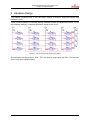
2 Hardware Design
This chapter introduces how to use the matrix method to create a keyboard function with
hardware circuit.
There are two methods to eliminate jittering, software method and hardware method. To use
the hardware method, a capacitor should be added to the circuit.
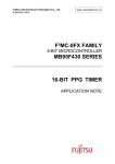
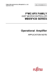
Figure 2-1: Circuit for Keyboard Design Using Matrix
As indicated in the figure above, P04 ~ P07 are used as output pins and P00 ~ P03 as input
pins to scan the keyboard status.
MCU-AN-500038-E-10 – Page 5
Keyboard Development Using Matrix V1.0
Chapter 3 Keyboard Development
3 Keyboard Development
This chapter introduces how to develop the keyboard using matrix.
3.1
Function of Matrix Circuit
The Keyboard is an important tool for the input system. This reference design is used to
show how to save I/O pins when adopting keyboard with many keystrokes.
A real-time monitoring method for polling the keyboard status is also used. The period of
polling is a fixed value. It means any movement slower than this value will be caught by the
monitoring software. It will ensure the high responding action of the keyboard.
3.2
Jittering Elimination
Jittering elimination is a problem for keyboard design. There are two methods to resolve this
problem. One is to add a capacitor to the hardware circuit. The other is to design a delay by
using the 8/16-bit composite timer.
3.3
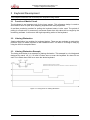
Jittering Elimination Example
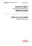
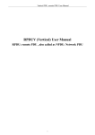
The timing chart below is an example of jittering elimination. This example is a 4×4 keyboard
designed by matrix. X0, X1, X2 and X3 takes turns to scan the keyboard for about 50 ms
each. So it takes about 200 ms to scan the whole keyboard.
Figure 3-1: Timing Chart for Jittering Elimination
MCU-AN-500038-E-10 – Page 6
Keyboard Development Using Matrix V1.0
Chapter 4 Resource Usage
4 Resource Usage
This chapter introduces evaluation steps of normal run status.
To monitor the keyboard status, I/O pins are necessary. This chapter will introduce the
usage of I/O port. Please refer to Chapter 9 of the MB95200 Series Hardware Manual for
detailed register setting.
4.1
Register Introduction
4.1.1 Port Data Register (PDR)
This register contains bit information of corresponding input or output pins. The values are
output, if the Port Direction Register is set to output mode.
Please note that the resource output control bit overwrites the PDR bit value.
PDRx_yz
0
Pin
Function
Pin state low (VSS)
1
Pin state high (VDD)
4.1.2 Data Direction Register (DDR)
This register contains the bit information of the corresponding pins if they act as input or
output.
DDRx_yz
Peripheral Function Output
0
Disable
1
Disable
invalid
Pin Function
Port Input
Port Output
Enable
Peripheral Function Output
4.1.3 Pull-up Control Register (PUL)
This register connects an internal pull-up resistor to a port pin.
PULx_yz
Pull-up Resistor
0
Disable
1
Enable
Please see datasheet for the resistor value.
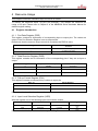
4.1.4 Input Level Selection Register (ILSR)
With this register one of the following input levels can be chosen.
ILSR
Input Level
VIL
0x04
CMOS
0.3 VCC
0x00
Hysteresis
0.3 VCC
Please note that this function is available only in PDR0_P04.
MCU-AN-500038-E-10 – Page 7
V
I
0.7
VCC
0.7
VCC
Keyboard Development Using Matrix V1.0
Chapter 4 Resource Usage
4.2
General Introduction
I/O pins which are necessary in this system can be classified into two groups: output pins
and input pins. The output pins are used to output high voltage while the input pins are used
to scan the keyboard status.
4.2.1 How to Set Input Pin
If a pin functions as an input port, the corresponding bit in the Data Direction Register should
be set to “0”.
To set an externally connected source to high-Z state, please use an external pull-up or pulldown resistor or set the corresponding bit in the Pull-up Register
There are three types of input modes: digital input, ADC input and peripheral function input:
Digital input means the port is used as general I/O.
ADC input means the port is used for analog input only.
Peripheral function input means the port is used by a peripheral function as input,
such as external interrupt input.
4.2.2 How to Set Output Pin
There are two kinds of output modes: digital output and peripheral function output.
Digital output means the port is used as general I/O.
Peripheral function output means the port is used for peripheral resource output such
as output of 8/16-bit compound timer.
4.2.3 Pull-up Register
The P0 and PG ports, when in input-mode, can enable an internal pull-up resistor (about 50
K Ω, please see datasheet for the exact value) by programming the pull-up register (2.2.3).
The initial value of “0” disconnects the internal pull-up resistor. Writing “1” to the
corresponding bit in the PULx register enables the resistor.
If the port is used for output, the value of the register-bit has no meaning and the pull-up
resistor is disabled (Exception: For I2C pins SDA and SCL, the setting remains. Also for
UART output SOT the internal pull-up can be used if not provided by line driver).
The pull-up resistor is disabled when the microcontroller is in stop or timer mode.
The resistor is also disabled if the pin is used for ADC input.
If an external pin is used by the external bus interface, the internal pull-up register cannot be
used.
MCU-AN-500038-E-10 – Page 8
Keyboard Development Using Matrix V1.0
Chapter 5 Software Design
5 Software Design
This chapter describes how to develop a keyboard by matrix.
5.1
Software Design
To realize this function, first initialize the I/O register, and setup the AD input forbid, then
enable the timer interrupts to eliminate jittering. The output I/O pin outputs high voltage and
MCU waits for the input signal. Refer for to the hardware circuit, if some keys pressed, the
MCU will scan this information and transact the corresponding key function.
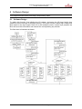
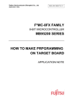
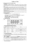
The flow chart is illustrated as below:
MCU-AN-500038-E-10 – Page 9
Keyboard Development Using Matrix V1.0
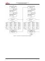
Chapter 5 Software Design
Figure 5-1: Flow Chart of Keyboard Development by Matrix
MCU-AN-500038-E-10 – Page 10
Keyboard Development Using Matrix V1.0
Chapter 6 Sample Code
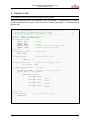
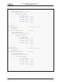
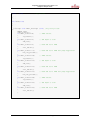
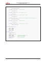
6 Sample Code
This chapter illustrates keyboard development using Matrix.
Based on MB2146-410-01, the following code is intended to illustrate how to create a
keyboard function with I/O port. Port 0 is used for detecting key status. The default level of
input is high.
/* THIS SAMPLE CODE IS PROVIDED AS IS AND IS SUBJECT TO ALTERATIONS.
/* FUJITSU SEMICONDUCTOR ACCEPTS NO RESPONSIBILITY OR LIABILITY
/* FOR ANY ERRORS OR ELIGIBILITY FOR ANY PURPOSES.
/* (C) Fujitsu Semiconductor (Shanghai) Co., LTD.
/*-------------------------------------------------------------------/* Give a example for basic I/O matrix */
#include "../MB95200_IO/mb95200.h"
void timer_init(void)
{
T01DR = 0x13;
// 5000us
T00DR = 0x88;
TMCR0 = 0x10;
// 16-bit
T00CR0 = 0x81;
// interval timer with continuous mode
T00CR1 = 0xA0;
// disable output, start timer
}
/*P04 SCAN*/
void IO_restart(void)
// PDR0 restart
{
PDR0 = 0xFF;
}
void P04_low(void)
// Pin P04 begin to scan
{
PDR0_P04 = 0;
}
void Port_Value1(void)
// Read and store PDR0 in value 1
{
port_value1 = PDR0;
}
void Row_one_process(void) // key judge
{
port_value2 = PDR0; // Read and store PDR0 in value 2
if(port_value2 == port_value1)
{
switch(port_value2)
{
case 0xEE: SW1();
break;
case 0xED: SW2();
break;
case 0xEB: SW3();
break;
case 0xE7: SW4();
break;
}
}
}
/* P05 scan*/
void P05_low(void)
// Pin P05 begin to scan
{
PDR0_P05=0;
}
MCU-AN-500038-E-10 – Page 11
*/
*/
*/
*/
*/
Keyboard Development Using Matrix V1.0
Chapter 6 Sample Code
void Row_two_process(void)
// key judge
{
port_value2 = PDR0;
if(port_value2 == port_value1)
{
switch(port_value2)
{
case 0xDE: SW5();
break;
case 0xDD: SW6();
break;
case 0xDB: SW7();
break;
case 0xD7: SW8();
break;
}
}
}
/* P06 scan*/
void P06_low(void)
// Pin P06 begin to scan
{
PDR0_P06=0;
}
void Row_three_process(void)
// key judge
{
port_value2 = PDR0;
if(port_value2 == port_value1)
{
switch(port_value2)
{
case 0xBE: SW9();
break;
case 0xBD: SW10();
break;
case 0xBB: SW11();
break;
case 0xB7: SW12();
break;
}
}
}
/* P07 scan*/
void P07_low(void)
// Pin P07 begin to scan
{
PDR0_P07=0;
}
void Row_four_process(void)
// key judge
{
port_value2 = PDR0;
if(port_value2 ==port_value1)
{
switch(port_value2)
{
case 0x7E: SW13();
break;
case 0x7D: SW14();
break;
case 0x7B: SW15();
break;
case 0x77: SW16();
break;
}
}
MCU-AN-500038-E-10 – Page 12
Keyboard Development Using Matrix V1.0
Chapter 6 Sample Code
void SW1(void)
// Key Process
{
. . .
}
. . .
. . .
void SW16(void)
{
. . .
}
. . .
__interrupt void Timer_Interrupt (void) //key scan process
{
T00CR1_IF=0;
timer_counter++;
if(timer_counter==0)
// PDR0 restart
{
IO_restart();
}
if(timer_counter==4)
// P04 begin to scan
{
P04_low();
}
if(timer_counter==5)
// Read and store PDR0
{
Port_Value1();
}
if(timer_counter ==9)
// Read and store PDR0 and judge keypressed
{
Row_one_process();
}
if(timer_counter==10)
// PDR0 restart
{
IO_restart();
}
if(timer_counter==14)
// P05 begin to scan
{
P05_low();
}
if(timer_counter==15)
// Read and store PDR0
{
Port_Value1();
}
if(timer_counter==19)
// Read and store PDR0 and judge keypressed
{
Row_two_process();
}
if(timer_counter==20)
// PDR0 restart
{
IO_restart();
}
if(timer_counter==24)
// P06 begin to scan
{
P06_low();
}
if(timer_counter==25)
// Read and store PDR0
{
Port_Value1();
}
MCU-AN-500038-E-10 – Page 13
Keyboard Development Using Matrix V1.0
Chapter 6 Sample Code
if(timer_counter==29) // Read and store PDR0 and judge keypressed
{
Row_three_process();
}
if(timer_counter==30) // PDR0 restart
{
IO_restart();
}
if(timer_counter==34) // P07 begin to scan
{
P07_low();
}
if(timer_counter==35) // Read and store PDR0
{
Port_Value1();
}
if(timer_counter==39) // Read and store PDR0 and judge keypressed
{
Row_four_process();
}
if(timer_counter==40) // PDR0 restart
{
IO_restart();
}
if(timer_counter>=41) // Timer_counter restart
{
timer_counter=0;
}
}
void clock_Select(void)
{
SYCC = 0x00;
WATR = 0x00;
STBC = 0x01;
SYCC2= 0xF4;
}
void main(void)
{
InitIrqLevels();
__EI();
timer_counter =0;
DDR0 = 0xF0;
AIDRL = 0xFF;
clock_Select();
timer_init();
while(1);
//P00~P03= in P04~P07=out
//Port input enable
//Main clock select
//Timer initialize
}
MCU-AN-500038-E-10 – Page 14
Keyboard Development Using Matrix V1.0
Chapter 7 Performance Evaluation
7 Performance Evaluation
To eliminate jittering, there are hardware method and software method. Though the code of
hardware method is very simple, only using the timer calculagraph, its effect is not good,
because the system may not be able to scan the edge. By comparison the software method
is better.
MCU-AN-500038-E-10 – Page 15
Keyboard Development Using Matrix V1.0
Chapter 8 Additional Information
8 Additional Information
For more information about how to use MB9595200H/210H EV-board, BGM Adaptor and
SOFTUNE, please refer to SKT MB2146-410A-01-E User Manual, or visit websites:
English version address:
http://www.fujitsu.com/cn/fsp/services/mcu/mb95/application_notes.html
Chinese version address:
http://www.fujitsu.com/cn/fss/services/mcu/mb95/application_notes.html
MCU-AN-500038-E-10 – Page 16
Keyboard Development Using Matrix V1.0
Chapter 9 Appendix
9 Appendix
Figure 2-1: Circuit for Keyboard Design Using Matrix .............................................................. 5 Figure 3-1: Timing Chart for Jittering Elimination ..................................................................... 6 Figure 5-1: Flow Chart of Keyboard Development by Matrix ................................................. 10 MCU-AN-500038-E-10 – Page 17