1
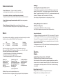
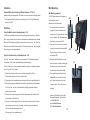
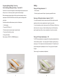
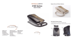
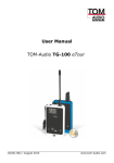
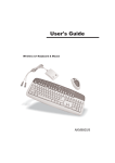
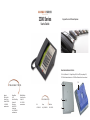
3300 Series Single and Two Line 3300 Series Telephones: User’s Guide Base Underside Features & Controls 23. Non-Slip Rubber feet 24. Voltage Settings - 24V, 48V and OFF (factory setting is 24V) 25. Wall Mount bracket attachment slots 26. Wall Mount Bracket with short line cord channel 25 America’s: 5025 Galley Road Colorado Springs Colorado 80915 USA +1.719.638.8821 www.telematrix.net Europe/Africa: Unit 33, Stratford Ofce Village Wolverton Mill Milton Keynes Buck MK12 5TW United Kingdom +44 (0) 1908 682180 www.telematrix.net Middle East/India: Hamriyah Free Zone Sharjah, UAE +971 4 2676550 www.telematrix.net 24 USA +1.719.638.8821 Europe +44 (0) 1908 682180 Middle East +971 4 2676550 23 26 Base Features and Controls: 3300 Series Features: 1. Handset 4a/b. MW Selector switches 7. Faceplate area 2. Wall Mount clip slot 5. Store key (submerged) 8. Line cord receptacle 3. Wall Mount Handset clip 6. Flash key (submerged) 9a. HSIA receptacle 9b. HSIA laptop port 1 2 4a 4b 5 3 6 7 8 LBY MWB MW10 MWD 2MWD MW5 MWD5 2MWD5 MWS 2MWS • Line Powered Telephone. 1-Line (1-L) & 2-Line (2-L) 1-L 1-L • SteelTrap™ Memory Technology (no batteries required). 9a 1-L 1-L 2-L ▲ ▲ ▲ • Handset wall mount clip engage slot #2 ▲ ▲ ▲ ▲ ▲ • Wall Mounting clip (turn 180º to attach handset) #3 ▲ ▲ ▲ ▲ ▲ • Message Waiting selector switch ON OFF (submerged) # 4a ▲ ▲ ▲ ▲ • Message Waiting selector switch TYPE LR1 LR2 (sub.) # 4b ▲ ▲ ▲ ▲ TYPE = auto LED or Neon, LR1 & LR2 = reverse polarity • Programmable Store key. (submerged) #5 ▲ ▲ ▲ • Programmable Flash key (submerged) #6 ▲ ▲ ▲ • Faceplate Display area #7 ▲ ▲ ▲ ▲ ▲ • Line Cord receptacle (top end of phone) #8 ▲ ▲ ▲ ▲ ▲ • HSIA RJ45 receptacle from wall (top end of phone) # 9a ▲ ▲ ▲ ▲ • Guest Services Memory keys (5 or 10 keys) # 10 ▲ ▲ ▲ • Ringer Volume switch - HI/LOW settings lines 1 & 2 # 11 ▲ ▲ ▲ ▲ ▲ • PassPort™ RJ45 High Speed Internet Access port # 9b ▲ ▲ ▲ ▲ • Programmable Pause/Redial key (exposed) # 12 ▲ ▲ ▲ ▲ • ADA Compliant Handset/Speaker Volume keys (8-step control) (2-step on 3300LBY) # 13a & 13b ▲ ▲ ▲ ▲ ▲ • Conference/Flash (Recall) Key (exposed) # 14 ▲ ▲ ▲ ▲ • Speaker key withOn/Off LED indication # 15 ▲ ▲ • Mute key with On/Off LED indication # 16 ▲ ▲ • Microphone # 17 ▲ ▲ • TouchLite Message Waiting key with1-touch retrieval # 18 ▲ ▲ • Speaker - half duplex # 19 ▲ ▲ • Handset coil cord receptacles # 20a/20b ▲ ▲ ▲ ▲ • Electronic Hold key with On/Off LED indication # 21 (used to program location in speed dial keys) (submerged) NEON Reverse Polarity L-1 Reverse Polarity L-2 20b 10 11 9b 12 13a 13b 14 (used to program delay in speed dial keys or to redial last call) (CONF on 2 line only, Flash/Recall on single line) 20a 19 21 22a 22b 10. Guest Services keys 11. Ringer Volume switches 12. Pause/Redial key 13a. Volume Controls ▲ 18 17 16 15 13b. Volume Control ▼ 14. Conf/Flash (Recall Key 15. Speaker Key with indic. 16. Mute Key with indicator 17. Microphone 18. 19. 20. 21. 22. TouchLite Message Waiting Speaker - half duplex Handset Coil cord receptacles Hold key with indicator Line 1 & Line 2 keys with indicators Version 09.24.08 ▲ ▲ ▲ ▲ • Line 1 and Line 2 keys with selected line LED indication # 22a/22b • Desk or Wall Mountable (wall mount bracket and short line cord sold seperately) # 26 ▲ ▲ ▲ ▲ ▲ TABLE of CONTENTS: MARQUIS Congratulations on purchasing a TeleMatrix telephone product. Our goal is to provide you with seamless endpoint communications. TeleMatrix is known worldwide for it’s telephony innovations, such as SteelTrap memory technology, which eliminated the need for batteries in telephones and gives you the added assurance that your speed dial keys will retain their memories, even in the event of loss of power. TouchLite is another revolutionary invention that allows you to simply press the message waiting light and you will retrieve your messages, vs. a complicated set of instruction to retrieve messages. Along with leading technological advances TeleMatrix believes strongly in quality control, both at the factory prior to being shipped, and again at our headquarters before they are sent to you. This is evident in our less than 1% return rate. With all this said, TeleMatrix understands that it is our people that truly make the difference. The company culture is one of excellence. The entire team from sales to production to shipping are all watching over your product, to ensure it is delivered on time, with the correct programming and faceplate, just as you have instructed. Our Priority Care department is set up specifically to assist you with the planning and post delivery of your telephone. Should you have any questions, run into difficulties, or are interested in learning more about your telephone, please do not hesitate to call our qualified professionals. They are eager to assist and extremely friendly, courteous and knowledgeable. Thank you for joining the TeleMatrix family! From the entire TeleMatrix Team. Please call for additional information or questions: Priority Care 1.800.462.9446 toll free N. America +1.719.638.8821 USA +44 (0) 1908 682180 Europe/Africa +971 4 2676550 Middle East/India Web sites www.telematrix.net www.telematrix.net www.telematrix.net 13 3300 Series Telephones Features Features & Controls Parts List Compliance/Safety page 1 page 2 page 2 PARTS CHECK LIST: Installation Caution Information Connecting Handset & Line Cord PassPort pass-through HSIA Switch Settings message waiting/line voltage Wall Mounting The following parts are included in this package: A. Line cord - 15 ft./4.5m. B. Handset coiled cord - 9 ft./2.5m. C. Base unit. D. Handset E. Printed Faceplate F. Protective plastic faceplate overlay Operation Handset & Speaker Volume Ringer Volume LED Indicators Mute Key Conference/Flash (Recall) Key Calling Speakerphone Key page 4 page 4 page 5 page 5 page 5 page 6 page 6 Programming Speed Dial Memory Keys Flash & Pause Timing Flash & Pause Memory Keys Message Waiting (TouchLite) page 7 page 7 page 8 page 9 Servicing Care & Maintenance Service Warranty page 11 page 11 page 12 INSTALLATION & USERS GUIDE The following are optional Items possibly included: (Must be ordered separately) G. Wall Mount Wedge & Short 6 inch to wall line cord. Please call TeleMatrix PriorityCare to order 1.800.462.9446 toll free N. America +1.719.638.8821 USA +44 (0) 1908 682180 Europe/Africa +971 4 2676550 Middle East/India page 3 page 3 page 3 page 4 page 10 COMPLIANCE & SAFETY: As specied by FCC regulation, we are required to inform you of specic governmental and compliance regulatory requirements, safety notices, safety instructions and other informative information. TeleMatrix, Inc.. provides this information in a separate manual. We place the separate Compliance and Safety Manual within each outer box or product box when shipped. Prior to reading this operation manual and prior to setting up your telephone, please refer to the Compliance and Safety Manual. If the Compliance and Safety Manual is not immediately available. Please obtain a free copy by calling our PriorityCare department (1.800.462.9446) or by downloading a copy on our Internet web site (www.telematrix.net). 2 Installation... Caution Information • Never install telephone or network wiring during a lightning storm. • Never install telephone or Ethernet jacks in wet locations unless the jack is specically designed for wet locations. STATEMENT OF LIMITED WARRANTY A 9 ft. modular handset coil cord is provided. To install, simply plug one end of the coil TELEMATRIX, INC.. warrants to its [original end customer] [purchaser] that Spectrum PLUS, Marquis and RETRO branded products manufactured by TELEMATRIX, INC. are free from defects in materials and workmanship for ve (5) years after the date of purchase, and Regency branded products manufactured by TELEMATRIX, INC. are free from defects in materials and workmanship for three (3) years, other than the following products for which the warranty period shall be one (1) year: handset batteries, either NiCd or NiMH, used in TELEMATRIX, INC. cordless products. If a product fails this warranty during the warranty period, TELEMATRIX, INC. will, at its option, either repair or replace the defective product or parts, or deliver replacements for defective products or parts on an exchange basis at no additional charge to the customer except as set forth below. Repair parts or replacement products may be either new or reconditioned. Products or parts returned to TELEMATRIX, INC. under this warranty will become the property of TELEMATRIX, INC. Warranties on products repaired by TELEMATRIX, INC. expire at the termination of the original warranty period. cord into the jack at the base of the handset, and the other end into the jack located on This limited warranty does not cover • Never touch uninstalled telephone wires or terminals unless the telephone line has been disconnected at the network interface. • Use caution when installing or modifying telephone and network lines. Connecting the Handset Cord - # 20a & 20b the left side of the telephone base marked “Handset”. Connecting the Line Cord - # 8 A 15 ft. modular line cord is provided. To install, simply plug one end of the cord into the modular jack at the top end of the base unit and the other end into the wall jack. 1. 2. 3. 4. 5. 6. 7. Products or parts which are damaged, abused or misused; Any damage resulting from improper installation, maintenance or operation of the product; Damage resulting from unauthorized modication or repair of the product, or from improper connection of the product to other equipment; Cords, connectors and replaceable batteries; Damage in transit to the TELEMATRIX, INC. repair facility; Any product or part unless proof of date of purchase is submitted with the product when returned for warranty repair; or Costs incurred by the customer in removing and shipping the product to TELEMATRIX, INC. for repair or replacement, and costs of reinstallation of the product. Products or parts which are not owned and used by the original end user customer. Connecting to the HSIA Port - # 9a & 9b 8. The phone is equipped with PassPort™, a High Speed Internet Access port on the right The cost and risk of loss or damage for sending the product to TELEMATRIX, INC. will be borne by the customer. side of the base unit. This receptacle acts as a pass-through so that the guest may conntect their laptop into the hotel’s high speed internet system for maximum effeciency. To connect - place the Ethernet cable from the wall into the RJ45 receptacle at the top end of the base # 8. (Does not apply to 3300LBY) TELEMATRIX, INC. EXPRESSLY DISCLAIMS ALL WARRANTIES EXCEPT THE LIMITED WARRANTY SET FORTH HEREIN, WHICH IS THE SOLE AND EXCLUSIVE WARRANTY OF THE PRODUCT, AND IS IN LIEU OF ALL OTHER WARRANTIES, WHETHER ORAL OR WRITTEN, EXPRESS OR IMPLIED, OR STATUTORY. THERE ARE NO IMPLIED WARRANTIES OF MERCHANTABILITY OR FITNESS FOR A PARTICULAR PURPOSE. THE CUSTOMER’S SOLE REMEDY UNDER THE TELEMATRIX, INC. WARRANTY SHALL BE REPAIR OR REPLACEMENT AS PROVIDED ABOVE. IN NO EVENT WILL TELEMATRIX, INC. BE LIABLE TO CUSTOMER OR ANY OTHER PARTY FOR ANY INDIRECT, INCIDENTAL OR CONSEQUENTIAL DAMAGES, INCLUDING, WITHOUT LIMITATION, DAMAGES OF LOST PROFITS, LOST REVENUES, LOSS OF USE OF FACILITIES OR EQUIPMENT, OR COST OF SUBSTITUTE EQUIPMENT ARISING OUT OF THE USE OR INABILITY TO USE THIS PRODUCT, EVEN IF THE CUSTOMER HAS ADVISED TELEMATRIX, INC. OF THE POSSIBILITY OF SUCH DAMAGES. TELEMATRIX, INC. LIABILITY FOR DAMAGES SHALL NOT EXCEED THE PURCHASE PRICE OF THE DEFECTIVE PRODUCT. This limited warranty is non-transferable without the prior written approval of TELEMATRIX, INC. It gives the customer specic legal rights. The customer may have other rights which vary under local law. Some jurisdictions may not allow limitations on the term of an implied warranty or exclusions or limitations of incidental or consequential damages. 3 12 Version 09.24.08 CARE AND MAINTENANCE Settings... Line Voltage Selectors (optional feature) - # 24 • Keep the telephone dry. If it gets wet, wipe it dry immediately. Liquids might contain minerals that can corrode the electronic circuits. • Use and store the telephone in a normal temperature environment. Temperature extremes can shorten the life of electronic devices and distort or melt parts. Two line telephones are equipped to operate behind a PBX telephone systems rated between 24 volts and 48 volts. There is a selector switch on the bottom of the phone (hidden). The switch has 3 settings “24V, 48V or Off”. Your phone must be set according to what your PBX system is rated. The preset to the “24V” setting. (Does not apply to single line telephones - no voltage settings on 1-lines) • Keep the telephone away from excessive dust and dirt that can cause premature wear of parts. • Wipe the telephone with a damp cloth occasionally to keep it looking new. Do not use harsh chemicals, cleaning solvents, or strong detergents to clean the system. SERVICE When problems arise during installation or service that cannot be resolved using this or related documents, contact your regional TeleMatrix PriorityCare department. Direct: Fax: USA +1.719.638.8821 +1.719.638.8815 Europe +44 (0) 1908 682180 +44 (0) 1908 682189 Middle East +971 4 2676550 +971 4 2677361 Many times a problem can be resolved by contacting a TeleMatrix support agent. Please contact TeleMatrix PRIOR to sending a telephone to our service center for repair. In the unlikely event that a factory repair is necessary: 1. Include a brief description of the trouble that you are experiencing. 2. Include a proof of purchase for a repair warranty. 3. Send the telephone prepaid by UPS or Parcel Post insured to: TeleMatrix, Inc. Customer Care Center 5025 Galley Road Colorado Springs, CO 80915 USA [email protected] TeleMatrix Europe, LTD Customer Care Center Unit 33 Stratford Ofce Village Wolverton Mill, Milton Keynes Bucks MK12 5TW United Kingdom TeleMatrix Middle East Customer Care Center Hamriyah Free Zone Sharjah, UAE [email protected] [email protected] TeleMatrix will pay to return the repaired telephone to you. Please feel free to check on its progress by calling your regional PriorityCare Department. 11 Message Waiting Selectors - # 4a & # 4b USA/Domestic Conguration: You may select from “NEON OFF or LED” switch settings. Check with your telephone switch provider to ensure the proper setting. European Conguration: This telephone automatically responds to both “NEON” or low-voltage “LED” signals via the “TYPE” setting. “LR1 & LR2” are for reverse polarity message signaling (LR means “line reverse”). If the wrong position is selected, the message lamp will be OFF when there is a message, and ON when there is no message. Moving the switch to the other position will correct this. # 4b. The telephone also has an ON OFF switch that turns the entire message waiting circuit on or off. The normal setting is “ON”. # 4a Operation... Volume... Handset & Speaker Volume Control - # 13a & 13b The handset volume control increases the volume of the handset. When the handset is off hook or speaker key engaged on speakerphones, press the volume control keys to increase or decrease the volume. The handset volume control is a 8-step operation, and 2-step operation for 3300LBY sets. All models are hearing aid compatible. Ringer Volume Control - # 11 The ringer volume control switch is on the right side of the phone. Settings are either Low or HI (High), for both lines 1 and 2. 4 Indicators... Wall Mounting... Speaker & Mute Key Connecting & Status Indicators - # 15 & 16 Wall Mounting (optional) Speakerphones are equipped with LED indicators to show the current feature key status. • Press Speaker or Mute Feature Key to use that service - LED will light Green when that key is IN USE. The 3300 Series telephones is designed to conveniently wall mount. Please follow these easy steps: 1. The handset retaining clip must be Features... Using the Mute Feature on Speakerphones - # 16 A “Mute” key is provided to allow privacy during a background conversation. When the “Mute” key is activated, the microphones in the handset and speakerphone are disabled. When the “Mute” feature is activated, the caller will not hear your voice. The “Mute” key will light to show that the feature is activated. To de-activate, press the “Mute” key again. (Does not apply to non-speakerphones) engaged to secure the handset when hanging it up. To engage the clip, unsnap the clip, rotate the clip 180 degrees and then snap the clip into place. # 3 2. Plug one end of a short line cord into the line jack on the back of the base unit # 8. Plug the other end of the line cord into Using the Conference Key on Speakerphones - # 14 The “Conf.” key is used to establish a 3-way conversation. The conference feature is 3. Attach the Wall Mount Bracket on to the back of the phone, placing mounting clips A 3-way “Conference” call can be established while using either the handset or speaker- into brackets slots - push in place until phone. To use the “Conf.” feature: you hear them snap into place. # 25. 1. Place the line that is currently in-use on Hold by pressing the “Hold” key. The line status indicator will turn from Green to Red. 4. Next, guide the phone with wall mount wedge # 26 onto the studs of the wall 2. The second call can be established by selecting the idle line key and dialing the call. jack. Press down rmly until you feel 3. When the second call is established, activate the 3-way conference call by pressing it snap into place. The unit is now wall “Conf.” key. Line 1 and Line 2 will automatically “bridge” together and all three mounted. parties can now converse. 4. To end the call, simply hang-up by placing the handset back in its cradle (on-hook) or by pressing the “Speaker” key. 5. If you wish to continue speaking with one of the callers and wish to “drop” the other caller, simply press the line key of the caller you wish to continue speaking with. (Does not apply to non-speakerphones) 5 # 27 # 25 # 26 the wall jack. # 27 activated by a “soft” key that will automatically reset when hung up. The other caller will automatically drop-off. #8 # 25 Please call PriorityCare to order Wall Mounting Wedge and Short Line Cord: +1.719.638.8821 USA +44 (0) 1908 682180 Europe +971 4 2676559 Middle East 10 #3 Programming Message Waiting 1-Touch Key TouchLite (Message Waiting) Into Memory - TouchLite # 18 Calling... Placing a Call Using the Handset - # 1 TouchLite is an innovation that integrates the visual message waiting lamp and a speed • Lift the handset. dial key onto one. It allows easy access for guests to retrieve messages. • Dial out by using the numeric dial pad or by pressing a speed dial location. When the message waiting lamp lights notify the guest that a message is waiting, a simple press of the Red TouchLite button connects the guest to the message center Receiving a Call Using the Handset or Speaker - # 1 & # 15 or front desk. • On a single line telephone, when the phone rings, either lift the handset or press the TouchLite also adds an additional memory location to this telephone. speaker key should you have a speakerphone, to begin the conversation. 1. Lift the Handset. • On a two line telephone, when the phone rings, the line LED indicator will blink to show 2. Press the STORE Key - # 5. which line the call is coming in on. Select the blinking line key, then lift the handset or 3. Enter the number to be stored using the numeric dial pad. press the speaker key should you have a speakerphone, to begin the conversation. 4. Press the red TouchLite key to store. 5. Hang up the Handset. (Does not apply to 3300LBY or 3300MWB telephones) Placing a Call Using the Speakerphone - # 15 The 3300 Series speakerphones are equipped with a high quality speakerphone feature to allow hands free operation. To use, simply press the “Speaker” key when placing or answering a call. The telephone line will activate automatically. The “Speaker” key will light up indicating that the speakerphone is in-use. To hang up, press the “Speaker” key again. (Does not apply to non-speakerphone telephones) 9 6 Programming... Storing “Pause/Redial” Into Memory - Pause # 12 To program Store # 5, Flash # 6 & # 14, and Pause # 12 Some of these programming keys are located under the faceplate and overlay, begin by lifting up faceplate and overlay, by either a paperclip or sharp pointer. If you are using your telephone anywhere that requires an access code for outside calls, you may need to add a “Pause” to the number to allow time for the outside line to connect. You can enter an many pauses as needed. Note: a “Pause” or “Flash” programmed into memory counts as one digit when storing Storing a Number Into Memory Keys - Store # 5 a number. Each location can store up to 32 digits in tone mode. 1. Lift the Handset. Note: a “Pause” or “Flash” programmed into memory counts as one digit 2. Press the STORE Key - # 5. when storing a number. 3. Enter the required access code using the dial pad. 1. Lift the Handset. 4. Press the “Pause” key. 2. Press the STORE Key - # 5. 5. Enter the digits to be stored using the numeric dial pad. 3. Enter the number to be stored using the numeric dial pad. 6. Press the desired memory location wherein the number is to be stored. 4. Press the desired memory location wherein the number is to be stored. 7. If additional numbers are to be stored, repeat steps 3 thru 7. 5. If additional numbers are to be stored, repeat steps 3 thru 5. 8. Hang up the Handset. 6. Hang up the Handset. (Does not apply to non-memory key telephones) (Does not apply to non-memory key telephones) Programming Flash Timing & Pause Timing Flash timing options are 100mS thru 1000mS, programmable in 100mS increments. The default Flash timing is 600mS. Pause timing options are 1.0 sec. thru 5.0 seconds. The default Pause timing is 3.6 sec. 1. Lift the Handset (off-hook position). “Flash” hook function - Flash # 6 & # 14 The Flash function is used to access PBX features or Telco line features such as Call Waiting. The Flash function is a 600mS timed line break. If the Flash function will be used often, store the feature into memory located for easy access as follows: 1. Lift the Handset then press the “Store” key. 2. Press the “Flash” Key - # 6 & # 14. 2. Press the “Store” key once - # 5. 3. Program “Flash” by pressing “1” for 100mS, “2” for 200mS, etc.... # 6 & 14 4. Exit programming by hanging up the handset. 3. Press the memory location wherein the “Flash” is to be stored. 4. Hang up the Handset. To program Pause follow the above sets, except at # 3 - do the following: 3. Programming “Pause” by pressing “1” for 1.0 sec., “2” for 2.0 sec., etc... # 12 7 8