1
.
-,~-
• ,
i--:...
I
.
'
.',
OPERATOR'S'
MANUAL
~..
,
1..·
.. q
".
SooperSpooler8
INTELI.lGENT PRINTER INTERFACE
MODEL 55 -1000
BY
COMPULINK
CORPORATION
LOIS.OIT, CO. 80501
(303) 651-201_
"::'10( -:J..C
7
i'
...
-----c-------.--.:=::::=:::=:==-==-:;::----.;=~':;"""""-
FEDERAL COMMUNICATIONS COMMISSION
RADIO FREQUENCY INTERFERENCE
STATEMENT
Th Is equ I pment generates and uses rad I 0 frequency energy.
I f not
I nsta II ed and used proper I y, that is, In str I ct accordance with the
manufacturer's Instructions, it may cause interference to radio and
te I ev is I on recept i on.
Th i s dev I ce has been tested and found to
comply with the limits for a Class B computing device In accordance
with the specification in Subpart F of Part 15 of FCC Rules, which
are
designed
to
provide
reasonable
protection
against
such
Interference In a residential Installation.
However, there Is no
guarantee
that
Interference will
not occur
In
a particular
application.
If this equipment does cause Interference to radio or television
reception, which can be determined by turning the equipment off and
on, the user Is encouraged to try to correct the Interference by one
or more of the following measures:
1.
2.
3.
4.
Reorient the receiving antenna.
Relocate the computer with respect ot the antenna.
Separate the computer from the reclever
Plug the computer Into a different outlet so that computer
and receiver are on different branch circuits.
If necessary, you should consult your dealer or an experienced
radio/television technician for additional suggestions. You may find
the fo II ow I ng book I et prepared by
the
Federa I
Commun I cat Ions
Commission helpful:
How
to
Identify
and
Resolye
Radio-TV
Interference Problems. This booklet Is available from the US
Government
Printing Office, Washington,
DC 20402, Stock No.
004-000-00354-4.
Warn i ng:
Th I s equ i pment has been certl fled to comp I y with
the
limits for a Class B computing device, pursuant to Subpart J of Part
15 of FCC Ru I es.
On I y computers and pr Inters cert If i ed to comp I y
with the class B limits may be attached to this device.
Operation
with non-certified equipment is likely to result in interference to
radio and TV reception.
WARNING
HIGH VOLTAGE EXISTS INSIDE THIS UNIT
THE CASE SHOULD ONLY BE OPENED BY A QUALIFIED PERSONI
Page
SooperSpooler Users Manual
Table of contents
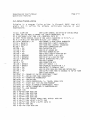
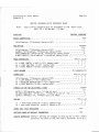
TABLE OF CONTENTS
SECTION
1.1
1.2
1.3
We Icome ..•
Registration
Lega II tl es ............... "
"
2.1
2.3
II
"
..
II
"
SPECIFICATIONS AND THEORY OF OPERATION
Overview of SooperSpooler Features
2-1
Theory of Operation
2-1
2-1
2.2.1 General Operation
. 2-4
2.2.2 Parallel Input/Output Port OperatIon
2.2.3 Serial Input/Output Port Operation
2-5
2.2.4 S Imu Itaneous Inputs from Two Computers •.•...•.•..••••.•••. 2-6
SpecifIcations
2-7
2 . 3 . 1 Ma r n Proce ssor
2-7
2-7
2.3.2 External Controls and Indicators
..
2.3.3 Internal SwItches ..•.•..•..•..•.
2-7
2.3.4 Software Selectable Functions •••..•
2-8
2.3.5 1/0 Ports
2-8
2.3.6 General SpecifIcations
2-9
SECTION 3
3.2
3.3
3.4
3.5
3.6
3.7
..
"
III
3. 1
1-1
1-1
. 1-1
II
...............................
SECTION 2
2.2
INTRODUCTION
"
..
III
..
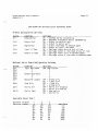
INSTALLATION
InItial Inspection
..
Power RequIrements •••.•.•••.•••.
Grounding Requirements
Environmental Requirements
ConfIguring to Your ApplIcation ••••••••.•.•..•.....•..•....••.••.
3.5.1 Primary Configuration SwItches
..
3.5.2 Serial Option Configuration Switches
.
Interfacing to Your Computer and Printer
3.6.1 The Interface Problem
3.6.2 Parallel Port Cables ••.••.
3.6.3 Serial Port Cables
Initial Operation
..
"
..
'"
"
"
II
..
"
II
'"
"
..
3-1
3-1
3-1
3-1
3-2
3-2
3-4
3-6
3-6
3-6
3-7
3-7
SooperSpooler Users Manual
Table of contents
Page II
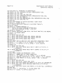
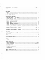
SECTION 4
4.1
OPERATIONAL FEATURES
External Controls and IndIcators
4. 1 • 1
Power Sw J tch
,. •••••••••.••..•..•.•••••.•
4.1 .2 Buffer Status Readout ....•..••....•...••.•..•••.•.•.•••...
4.1. 3 "Softlt Reset Pushbutton ••••••••••. ,. •.......•..........•...
4.1.4 Space CompressIon Pushbutton ••••••••••.•...............•.•
..
4.1. 5 Page Push button
4.1 .6 Single Sheets •.••••••.••••.••...•.•.•••......•.•••••.•••••
4.1. 7 Sa I f Test
4.1.8 "Hard" Reset Pushbutton
4.2 Software Controllable Features ..••••..•.•..•........•••••.••.•••.
4.2. t "Hard" Reset
..
4.2.2 Space Compress Ion
PagInation
.
4.2.3
'I
..
I
III
..
4.2.3.1 Headers •.•.•.•...•...•..••.••.•••...••.••.•••••..
4.2.3.2 Page Numberrng .•••.•••••••••••••••••....•....••.•
4.2.3.3 Single Sheets .•••••••.••.•••••••..•..•.....•••..•
4.2.3.4 Page Formatt I ng
.
L ~ ne Formatt I ng •.••••••••••••••••••••..•..••.••••••••••..•
4.3
4.2.4
4.2.5 Change COnfIguration SwItch Selected Items .•••.•••••••..•.
4.2.6 Redefine FF Character ••.•••••••••.•••••••..•............••
4.2.7 Redef Ine Lead r n Character •••••.••.•••••••••••••.....•••...
4.2.8 SeJf Test RoutJne .••••.•.•...•..•.••••••••••••••••.•.••.•.
.
Setup Program List J ng
APPENDIX A
4-t
4-1
4-1
4-1
4-2
4-2
4-3
4-3
4-4
4-5
4-6
4-6
4-6
4-7
4-7
4-8
4-8
4-9
4-9
4-11
4-11
4-11
4-12
INTERFACE INFORMATION
A.1 Paral lei Port Pinout and SIgnal DescrIption ••.•.••............•.• A-1
A.2 Paral lei Port TimIng Diagrams ••.••.••....••••...•..••••••••.•...• A-3
A.3 SerIal Port PInout and Signal DescrIptIon ••...................... A-4
APPENDIX 8
CONTROL SEQUENCE REFERENCE SHEET •••.........••••.••.••. 8-1
APPENDIX C
CONFIGURATION SWITCH REFERENCE SHEET ...••.•••.•..••••.• C-1
INDEX
1-1
SooperSpooler User's Manual
IntroductIon
Page 1-1
1.
1• 1
INTRODUCTION.
We I come •••
Thank you for selecting the SooperSpooler by Compullnk Corporation.
You
have purchased a high quality, extremely useful product that wi I I save you
hours of t I me wh i I e I ncreas I ng your pr I nt I ng power.
PI ease read through
this manual carefully to aid you In Installing your SooperSpooler and to
Instruct you In Its many features.
If you have any further questIons or
corrvnents, please feel free to write CompuJ Ink at any time for a prompt,
knowledgable reply.
In any communIcations wIth Compullnk, please state
your name, address, and your SooperSpool er model number, ser I a I number,
and options.
1.2
RegistratIon
As soon as you receive your SooperSpooler, fl II out and mall the
reg J strat Ion card.
You must be a reg I stered owner I n order to rece I ve
not I ce of fIrmware or hardware updates.
You may a I so e I act to rece I ve
Information on new Compul Ink products by checkIng the approprIate block on
the card.
You are not required to fill In aJ I the Information shown; you
may II st on I y your name and address I f you des f re.
Be assured that your
registration wll I not be used for outside "junk" mal lIng lists.
1.3
Lega I I tIes
The mater I a I In th I s document is for I nformat I ona I purposes on I y and Is
subject to change without notfce.
Compul Ink Corporation assumes no
I I ab I I r ty with respect to the use of or for any damages that may resu I t
from the use of any Information contained In this manual.
All rights
reserved.
Reproduction or use without express written permission, In any
manner, Is prohibIted.
AI I software contaIned In the ROM is copyrIghted by Compul Ink CorporatIon.
Duplication of thIs software, In whole or In part, Is strIctly prohIbIted.
PLEASE SEE THE FCC RAD I0 FREQUENCY
INSIDE FRONT COVER.
I NTERFERENCE STATEMENT LOCATED ON THE
SooperSpooler User's Manual
Specifications
2.
2.1
Page 2-1
SPECIFICATIONS AND THEORY OF OPERATION
Overview of SooperSpooler Features
Your SooperSpooler Model SS-1000 is a Z-80 mIcroprocessor control led,
Tntell rgent printer Interface.
Its basic functIon Is to accept data very
rap r d I Y from a host computer and feed that data to a pr r nter at the
printer's data acceptance rate.' ThIs elimInates the necessIty of waitIng
for your printer to complete printing before the computer may be used.
The SooperSpool er wIII a I so accept data from. or output data to. other
computer related devices.
Examples would Include accepting data from a
phone modem and outputtl ng to a pr I nter or us I ng the SooperSpool er to
"spool" data between a computer and a phone modem.
With the serIal
option, the SooperSpooler also wi I I act as a paral lei to serial or serial
to paral lei translator.
The base model contains 16K bytes of RAM, one parallel Input port and one
parallel output port.
A serial optIon Is available which provides two
addItional ports, serial Input and output.
A memory expansion optIon Is
available which Increases the memory to 62K bytes. 2K bytes of ROM contain
the operating firmware.
A two drglt numeric dtsplay IndIcates the amount
of data stored In the buffer memory.
In addition to the hardw9re spooling capabil tty, many Intel Ilgent features
are Incorporated to ease the job of printIng.
Pagination wIth software
sel€!ctable header, page numberIng, page size, and lines per page may be
enabled.
Print formatting allows independent control of left and right
margins,
and Indentation of carryover lInes.
Memory saving space
compression may be enabled.
Many of the Interface parameters may be
changed by hardware or software.
A self test routine Is built In.
Not.e
that the default of al I of these features Is "OFF" so that your data wll I
not be a I tered I n any way as I t passes through the SooperSpoo I er un less
spec J fica I I Y des ired.
2.2
2.2.1
Theory of Operation
General Operation
The heart of the SooperSpooler IntellIgent prInter interface Is the Z80
CPU microprocessor.
Under control of the program contained In a 2K x 8
bIt (2048 byte) type 2716 EPROM (Erasable, Programmable Read Only Memory),
It controls al I data Input. output and handshaking as wei I as the
"I nte I I I gent" features of the SooperSpoo I er.
I t exam I roes each character
received and determines whether to store the character In the buffer or to
change the configuratIon of the SooperSpooler.
As the printer Is ready to
accept another character, the CPU retr i eves the next character from the
bUffer, decIdes whether to output the character as Is, modIfy the
character, add more characters to the output, or further change the
configuratIon of the SooperSpooler.
Page 2-2
SooperSpooter User's Manual
Specifications
The l80 is capable of directly addressIng up to 64K (64 x 1024 = 65536
bytes) of memory.
The SooperSpooler Is set up so that the EPROM Is
addressed between 0 and 7FFH (hexadecimal), The 16K (16384 bytes) of
random access memory (RAM) '1'1 the base mode I Is addressed between COOOH
and FFFFH. 256 bytes of thIs memory Is used for scratchpad memory for the
l80, storing such thIngs as the present system configuratIon and top of
page header as we II as sav r ng var Iab Ies requ r red by the CPU 11'1 order to
execute the program stored In the EPROM. As exp I al ned Iater there are an
additional 100 bytes that, under normal conditions, are not avaIlable for
storage of characters sent to the SooperSpoo Ier, Ieav Ing a tota I of 16028
bytes for storage of data for pr I nt Ing.
The opt Iona I memory expans Ion
board contains an additIonal 48K of memory, addressed between 0 and BFFFH.
Since the fIrst 2048 bytes, addressed between 0 and 7FFH overlap the EPROM
memory addresses, this part Is not accessible for storage of data. With
the memory expansion board, there Is a total of 63132 bytes available for
data storage.
The l80 can a Iso address up to 256 Inputloutput ports.
6 ports are used for the fol lowing functions:
1.
2.
3.
4.
5.
In the base mode I,
Paral lei Input data port from computer.
Parallel output data port to prInter.
Output to BUFFER STATUS dIsplay.
Output to SPACE COMPRESSION and PAGE IndIcators.
Input ports to "read" the configuration swrtches, printer status and
front panel switches,
With the optIonal RS-232 serial Interface board, four more ports are used
for data to and from the computer and the prfnter, control and status of
the USARTs (Universal Synchronous Asynchronous Receiver Transmitter).
When the SooperSpooler Is fIrst turned on or whenever the hardware reset
sw Itch on the rear pane lis depressed, the l80 CPU (and the 8251 USARTS,
If the optional serial board Is Installed) Is (are) cleared by a master
reset signal. The l80, under control of the ROM program, then initializes
the SooperSpooler as fol lows:
1. Disable Interrupts, set l80 Interrupt mode and set the stack pointer.
2. Read the confIguration swItches and set up al I default values.
3. If the serial board Is Instal led, set the serial transmIssion
parameters according to the configuration swItches on the serial
board. Initialize the serial Input handshaking lIne and send DCl to
the computer serial port.
4. DetermIne the system memory size and set pointers for Input and output
data to the start of the buffer memory (lowest memory address).
5. InItialize the parallel Input port by readIng the Input data port and
output an ACKNLG* pulse to the computer paral lei port.
6. Check for closure of the PAGE pushbutton switch. 'If It is depressed,
then flash the PAGE Indicator to Inform the user that the sIngle
sheets mode has
the PAGE
been
IndIcator
se I ected.
Is flashIng.
No
pr' nter output w II I occur wh' Ie
The PAGE
depressed again In order to enable printer output.
pushbutton must
be
SooperSpooler User's Manual
SpecIfications
Page 2-3
Atter this InitialIzation procedure, the processor Interrupts are enabled,
allowIng data to be received from the computer. The ROM program directs
the CPU to perform the fol lowing steps:
1. If the buffer Is empty, then the CPU wI I I temporarIly dIsable
Interrupts and check for closure of eIther the SPACE COMPRESSION or
PAGE pushbutton swItch. If both are pressed, then the self test
routIne Is ImmedIately performed.
If either swItch is pressed
individually, then the mode correspondIng to the depressed swItch Is
toggled on or off.
Processor Interrupts are reenabled after pol lIng
the SPACE COMPRESSION and PAGE pushbutton swItches.
2. If the buffer is not empty, then the next character Is read from the
buffer and whatever actIon
Is
required on that character Is
performed. If the character is not a control sequence leadln
character or a space count (wIth space compressIon enabled), then the
CPU wll J output the character exactly as stored In the buffer to
eIther the paral lei or serial prInter output port. If the character
is a space count then the CPU wll I output that number of spaces to
the prInter.
If the character is part of a control sequence, then
the configuration of the SooperSpooler Is modIfIed according to the
remaInIng characters In the control sequence.
The buffer RESET
swItch Is pol led during this perIod, and If rt Is pressed, the lnput
and output buffer poInters are reset to the start of memory.
The
BUFFER STATUS
display Is contInuously updated as characters are
printed.
If a character Is sent to the SooperSpooler by way of eIther the paral lei
or ser Ia I , nput port and the CPU Interrupts are enab Ied, the processor
wIll ImmedIately start the character input procedure. Several thIngs may
occur In this routine:
1. If
the buffer Is fUll, handshaking Is performed with the host
computer to let It know that the SooperSpooler cannot accept data.
2. If space compression is enabled and a space Is sent, then the CPU
starts a pol led Input routIne, counting the number of spaces received
and storIng the count in the buffer with the most signIfIcant bit
(MSB) ; 1. AI I other characters received when space compressIon Is
enabled are stored In the buffer with the MSB ; O.
The polled input
contInues untIl either a non-space character Is receIved or the
number of consecutive spaces exceeds 127, at whIch tIme the space
count (and the followIng character, If not a space) Is stored In the
buffer
and the processor Interrupts are reenabled.
DurIng this
time, prInter output Is suppressed.
3. If a control sequence leadln character is receIved, the processor
pol Is the Input port untIl the control sequence Is completed. With
some exceptions, al I control sequences are stored In the buffer for
action to be taken after any data currently in the buffer Is sent to
the printer. Since space compressIon requires alteratIon of the Input
data, the space compression control sequence changes the method of
data storage as soon as It Is received. The control sequences for
self-test and reset cause the SooperSpooler to perform these actions
ImmedIately, even If there Is data stored In the buffer.
Printer
output Is suppressed during the pol led Input routIne.
Page 2-4
SooperSpooler User's Manual
SpecifIcations
4. AI I other characters received wIth space compressIon
stored In the buffer exactly as received.
During the Interrupt driven Input routine,
updated after every 256 characters.
dIsabled
the BUFFER STATUS display
are
Is
During the pol led Input routInes for space compression and control
sequences, the buffer status Is not checked.
Since there Is a possibilIty
of a control sequence be i ng started when the buffer (s near I y fu I I, the
buffer full status Is set when 100 bytes remain In the buffer.
This
al lows the complete set of control
sequences to be sent to the
SooperSpool er under software contro I when the buffer I s near I y f u I I.
As
soon as the control sequences are transferred, the buffer status wIll be
set to the f u I I state and handshak r ng set so that no more data can be
transferred untIl the buffer is ready.
When the buffer full status Is set, the SooperSpooler wIll not accept any
more data
unt i I
there are at I east 1024 bytes ava I I ab I e I n the buffer
(Including the 100 bytes mentIoned in the precedIng paragraph>.
The maxImum Input data rate (parallel
Input> Is approxImately 3000
characters per second.
I f the output from the computer I s fast enough to
exceed thIs rate, then the processor wI I I be interrupted as soon as
interrupts are enabl ed and no prl nter output wi II occur untl I the Input
rate eIther slows down or stops.
Input data rates slightly less than the
maximum will allow some printer output but the output data rate wi II be
much slower than normal whIle Input continues.
2.2.2
Parallel
Input/Output Port OperatIon
The SooperSpooler parallel Input and output ports are compatIble with all
Centronics compatible printers usIng a 36-pin Amphenol 57-series or
equivalent connector.
PrInters using other types of connectors may be
compat I b I e l f the data and handshak I ng I J nes are of the proper pol ar J ty
and meet the minimum tIming requirements as follows.
TTL sIgnal levels
are used In this Interface and the data lines are positive logIc (logIc 1
> 2. a vo I ts , log I c 0 < 0.8 vo I ts ).
Parallel Input from the computer may be run without handshaking If the
data rate Is less than 2500 characters per second (no less than 400
microseconds between characters). However, any data sent after the buffer
Is ful I wll I be lost. Handshaking to the computer may be accomplIshed by
use of either the BUSY line (p In 11) or the ACI<NlG* II ne (pT n 8) on the
36-pln receptacle.
If the BUSY line Is used, the computer must sample
th 1s line and not send data when the I I ne I s at the log I c 1 I eve I. Th i s
line goes hIgh ImmedIately fol lowing the leading edge of the STROBE*
signal.
If ACKNlG* is used, the computer must walt for the receIpt of the
ACKNlG* pulse from the SooperSpooler before sending another character.
The duratIon of the ACKNLG~ pUlse Is approxlm~iely 10 mlcro5econds. Thl5
pu I se Is sent after the SooperSpoo I er has accepied ihe character.
When a
Page 2-5
SooperSpooler User's Manual
SpecIfications
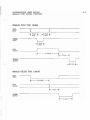
character Is sent to the SooperSpooler parallel Input port, the data lines
(pIns 2-9) must be stable for a minimum of 1 microsecond before the
STROBE* pulse Is sent, and must be held for a minimum of 1 mIcrosecond
after STROBE* goes to the high state. The mrnlmum duration of the STROBE*
pUlse Is 1 mIcrosecond. (See paral lei port timing diagrams - Appendix A).
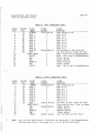
The fol lowIng prInter status lines are set to the IndIcated levels on the
computer parallel Input port:
PIN
12
13
32
Signal
Description
PE
SLCT
FAUL T*
Logic level
o
Printer out of paper
Printer selected
Printer error
1
1
The prInter output port uti I Izes the following lines for handshaking and
control:
PIN
Signal
DescrIptIon
BUSY
PE
FAULT*
11
12
32
Logic level
PrInter busy
Printer out of paper
PrInter error
o
o
1
All lInes must be at the logIc levels shown In order for the SooperSpooler
to output data to the pr Inter.
I f your pr Inter does not have some of
these then those that are not used may be left open circuIted If logic 1
Is required or shorted to ground If logic 0 Is requIred.
The tim r ng of the data I Ines and STROBE* I r nes for the pr Inter para I I e I
output port Is shown In Appendix A.
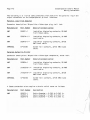
2.2.3
Serial Input/Output Port Operation
There are three handshaking protocols supported
selected by confIguratIon switch 51-1 as fol lows:
by the SooperSpooler,
S 1-1
Protocol
OFF
ON
Hardware (OTR lIne - pin 20) or software (OC1/0C3)
Software (ETX/ACK)
The hardware handshaking Involving the DTR line Is sImi lar in operation to
the prInter BUSY handshaking used In the parallel interface. The DTR line
Is set to the positIve EIA level (approximately +12 volts) when the
SooperSpoo Ier J s ready to accept data, and to the negat Ive EIA Ieve I
(approxImately -12 volts) when data cannot be accepted.
Page 2-6
SooperSpooler User's Manual
SpecIfications
The SooperSpooler wll I not output data to the printer unless pin 20 is at
the positive EIA level (must be greater than +3 volts).
This applIes even
If software type handshaking Is being used.
The two software handshaking protocols functIon as fol lows:
The DC1/DC3 (also known as XON/XOFF or control-Q/control-S) protocol ls
sImIlar to the hardware handshaking protocol In that the output device
(SooperSpooler to computer or printer to SooperSpooler) InItiates the
handshak r ng. When the pr r nter 1s ready to accept d~ta, I t sends an ASCII
character DCl (11 hexadecImal, 17 decimal) to the SooperSpooler.
When It
Is not ready, it sends an
ASCII DC3 (13 hexadecimal, 19 decImal) to the
SooperSpooter.
Likewise, the SooperSpooler sends these characters to the
computer for the same purpose.
The ETX/ACK protocol differs In that the Input devIce InitIates the
handshakIng. The computer wI II send a block of data (say 128 characters)
to the output devIce (prInter or SooperSpooler), fol lowed by an ASCI I ETX
(3) (end of text character).
The output device wIll respond with an ASCII
ACK (6) (acknowledge character) when It can accept more data.
Us I ng the ETX/ACK protoco I, the SooperSpool er wIt I send an ACK character
to the computer on I y I f there are at I east 1024 bytes ava r I ab I e I n the
buffer. I f the number of characters sent I n the block by the computer r s
greater than 1023, then some characters may be lost.
When an ETX character Is receIved by the SooperSpooler, It Is stored In
the buffer. After the ETX is sent to the pr'nter, the ScoperSpooler walts
for the printer to return an ACK character.
The SooperSpooler does not
InItIate the ETX protocol by Itself, usIng Instead the ETX character
provided by the computer.
If It Is desired to use a parallel output
computer to send data to the SooperSpooler, and have the SooperSpooler
output to a serIal prInter using the ETX/ACK protocol, some provIsIon wI I J
have to be made In the computer software for supplying the ETX character
In the paral lei output at least every 1023 bytes.
2.2.4
SImUltaneous Inputs from Two Computers
The SooperSpooler may be connected to two Input devices and to two output
devIces. The output device (serial or paral leI) may be selected either by
the configuration swItch or by a software control sequence.
The devIce
selected for Input wfll depend entirely upon the tImIng of the Input
sIgnals.
The parallel Input Is gIven the hIghest priorIty In order to
maximize speed.
If the parallel Input Is driven at a rate exceeding the
maximum rate that the SooperSpooler can accept data, then any Input to the
ser I a I port w r I I be lost, as no handshak I ng w r I I be prov 1ded for the
serIal port.
If the parallel Input Is driven at a rate slower than the
SooperSpoo[er maxImum rate, then any simUltaneous rnput from the serIal
porT wIll be mIxed wITh InpUT from The pared lei porT, creaTIng ambIguous
data.
If It Is desired to connect two Input devIces to the SooperSpooler
Then any arbiTratIon between The two devIces Is left to the user.
SooperSpooler User's Manual
SpecIfIcatIons
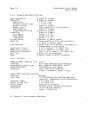
2.3
2.3.1
Page 2-7
SpecIficatIons
MaIn Processor
Processor
Clock Frequency
Memory
2.3.2
Z-80
1.8432 MHz
16K bytes RAM standard, expandable to 62K
(356 bytes reserved for system use)
2K ROM fIrmware control code
External Controls and Indicators
Reset Pushbutton
(front panel)
Reset Pushbutton
.( rear pane I )
Page Pushbutton
Space Compression
Pushbutton
Self Test Pushbuttons
SIngle Sheets
*
*
*
*
*
Buffer Status Readout
Power Switch
2.3.3
"Soft reset ll • Resets text buffer to empty.
PrevIously set parameters are not reset.
"Hard reset". Resets al [ parameters to
power-up condItion.
Enables automatic pagination. Indicator
LED lIghts when enabled
Enables space compressIon function.
IndIcator LED lIghts when enabled.
PressIng both the above pushbuttons enables
the self test routIne.
Enabled by holding the page button In
during turn-on or "Hard" reset
Continuous dIsplay of amount of text In
buffer (In kilobytes)
Main power I rne switch
Internal SwItches
I/O Baud Rate (6 switches)
Character length
Number of stop bIts
Parity Enable
ParIty check
SerIal protocol select
Printer output
Input CR!LF Set
*
Output CR/LF Set
*
Form Feed type
*
* = Feature
110,150,300,600,1200,2400,4800,9600 Baud
Select 7 or 8 data bIts
Select 1 or 2 stop bits
Enable or disable parIty bit
Select odd or even parity bit
DC1!DC3 or ETX/ACK
Select paral lei or serIal output
Select whether computer outputs CR only
or CR/LF at end of lIne
Select whether printer requires CR only
or CR!LF to advance paper
Select ASCI I FF or multiple lIne feeds to
advance paper to top of form
Is also software selectable
SooperSpooler User's Manual
Specifications
Page 2-8
2.3.4
Software Selectable Functions
Space Compression
PaginatIon
Page Length
Printed lines per page
Header Printing
Header Input
Page Numbering
Stngle Sheet PrintIng
Formattl ng
Left MargIn
RIght MargIn
Indentation
Printer output
CR/LF Set
# Enable or dIsable
# Enable or dIsable
Form Feed type
#
Redefine FF (Input)
RedefIne FF (output)
Redefine ESC Character
Self Test
Reset
#
#
2.3.5
#
#
#
1 to 127 lines
1 to 127 I Ines
Enable or disable
Input header up to 70 characters
Enable or dIsable
Enable or disable
Enable or disable
Co Iumn 1 to 127
Column 10 to 255
Co 1umn 1 to 127
Parallel or SerIal output
Select whether prInter requires CR only
or CR/LF to advance paper
Select ASCI I FF or multIple line feeds to
advance paper to top of form
o to 31 (default = 12 (ASCII FF»
o to 31 (default = 12 (ASCII FF»
ASCII 0 to 31 (default = 28 (ASCII FS»
Start self test procedure
Restore power up default parameters
I/O Ports
PARALLEL PORTS (standard on all un Its)
Interface
8-blt data compatIble with Centronics
BUSY, ACKNLG*, PAPER EMPTY, FAULT*
Handshaking & status lines
Maximum Data Rate
3000 Characters per second
36-pln CentronIcs Compatible
Connectors
(Input = receptacle, output = plug)
SERIAL PORTS (optional additIon)
RS-232C
Interface
Data rates
110,150,300,600,1200,2400,4800,9600 baud
(Each port Independently swItch selectable)
7 or 8 data bIts
Character length
1 or 2 stop bits
Number of stop btts
Even, odd or no parity
ParIty select
Hardware and/or Software handshaking
Handshaking
Input = 08-255 receptacle
Connectors
Output = DB-25P plug
# = Feature Is also hardware selectable
,-
Page 2-9
SooperSpooler User's Manual
Specifications
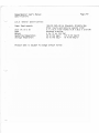
2.3.6
General SpecificatIons
Power Requirements
Size (H x Wx D)
Case
Weight
Operating Temperature
Storage Temperature
105-135 VAC, 60 Hz Standard, 20 Watts Max
Other Inputs available by specIal order
3.1 x 10.3 x 8.6 Inches (7.8 x 26.2 x 21.8
Anodized aluminum
4 Ib, 12 oz (2.2 Kg)
50 to 104 deg F
(10 to 40 deg C)
32 to 140 deg F
(0 to 60 deg C)
Product data fs subject to change without notice
I
em)
500per5pooler User's Manual
Insta I Iat Ion
Page 3-1
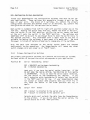
3.
3.1
IN5TALLATION
Initial InspectIon
ThIs unit was carefully inspected both mechanically and electrically at
the factory before shipment.
It should be In perfect operating condItIon
upon recel pt.
If your 500per5poo Ier appears to have been damaged In
transIt, Immediately file a claIm wIth the carrier.
If the unit does not
function properly, return It to your dealer (or to Compul Ink If you
purchased factory dIrect) with a ful I descrIption of the problems
encounterred. Please read the sections on Interfc:ce problems and cabling
0.6 to 3.6.3) before deciding you have a defective unIt. Most problems
usually are the result of errors In InterconnectIon and can be resolved by
double checking the cabling.
3.2
Power Requirements
The standard 500per5pooler Model 55-1000 Is desIgned to be operated from a
power source of 105 to 130V, 60 Hz AC. Power dissipation Is approxImately
15 Watts. A 1/4 Amp slo-blow fuse Is located Internally. A spare fuse
and an AI len wrench are [ncluded should replacement become necessary. The
power cord and plug use a standard three conductor groundIng arrangement.
Other Input power reqUirements are avaIlable upon special order.
3.3
GroundIng Requirements
Your 500per5pooler is equipped wIth a three prong groundIng type plug.
Proper grounding Is necessary to insure protection of the user from
hazardous electrical shock, to minimize electromagnetIc Interference, and
to protect your unit from statIc discharges. Do not attempt to defeat the
purpose of the groundl
3.4
Environmental Requirements
This unIt wll J operate reJ lably at temperatures normally found In the home
or offIce. As It does dIssIpate around 15 watts of power durIng normal
operation, some precaution must be taken to Insure an adequate aIr flow
around the unit to prevent overheatIng. One-half Inch of free aIr space
on all sides Is adequate. The operating temperature specificatIon Is 50
to 104 deg F (10 to 40 deg C), and the storage temperatu re spec If Icat r on
Is 32 to 140 deg F (0 to 60 deg C).
SooperSpooler User's Manual
Installation
Page 3-2
3.5
ConfIguring to Your Application
Inside your SooperSpooler are confIguration swItches that must be set per
These sw Itches are access IbIe through a port on the
your app II cation.
back of your un It.
One block of 5 sw Itches, S1, conta In the pr r mary
configuration switches and another block of 10 switches, S2, contain the
configuration swItches for the optional serial board.
Each switch Is numbered from left to right wIth position number one on the
left end. Pushing the switch away from you, toward the front of the unit,
sets the switch In the "ON" position, pulling the switch toward the back
of the un it sets the sw Itch in the "OFF" pos r t Ion.
The sw Itches are
sometimes stiff so be sure to use enough force to move the switch fully to
the des Ired pos It Ion.
Any Instrument with a sma I I hook on one end Is
suitable for moving the switches; a bent paper Clip works well. Be sure
the power Is turned off before attempting to change any of the switches.
Only the baud rate switches on the serial option board are checked
continuously during operation;
the SooperSpooler will sense any other
switch changes only upon power up or "hard" reset.
3.5.1
Primary Configuration Switches
The primary conf!guratTon switches (S1) perform the functions as fol lows.
Set each switch to the position which corresponds to your appl feat Ion.
PosltTon #1
SerIal
Handshaking
Select
OFF = XON/XOFF and hardware handshaking
ON = ETX/ACK handshaking
Used only If you have the serial option installed. IF YOU
DO NOT HAVE THE SERIAL OPTION, THE POSITION OF THIS SWITCH
IS UN IMPORTANT. If you do have the ser' a I board Insta I led,
set the switch to the handshaking you require.
If you
can't determine which handshaking to select, set the switch
If your SooperSpooler does
in the "OFF" position for now.
not accept or output data proper Iy when you first try f t
out, move the switch In the other position and try It
again.
PositIon #2
Output
OFF
ON
Port
Select
= Output Is directed to the serral port
=
Output Is directed to the paral leI port
Selects which port outputs the data from the SooperSpooler
to the pr Inter. If you do not have the ser ia I opt r on, the
switch should be In the
"ON" posrtlon.
-~,
SooperSpooler User's Manual
InstallatIon
Position 113
Form
Page 3-3
Feed Type
OFF ; Output multIple I ine feeds to advance paper
ON = Outpui form feed character to advance paper
Some printers wI! I not advance the paper automatIcally upon
receipt of a form feed character and requIre multiple tine
feeds to achieve the top of form function.
If your
printer wi I I act upon a form feed character, set this
sw I tch to "ON", otherw Ise set I t "OFF" to ach I eve proper
I f you don't know wh I ch form feed type you
pag I nat Ion.
requ 1 re, set th I s sw r tch to "ON" for now.
I f you find
during operation that thIs eliminates the form feed
function, move the swItch to "OFF" and try It again.
If you wish to set a form length other than the default of
lines (see page formatting, SectIon 4.2.3.4), this
switch must be set to "OFF" to allow your SooperSpooler to
calculate and output the correct number of sIngle I rne
feeds required to reach the top of the non-standard form.
66
PosItion #4
Computer Line Feed Select
OFF
= Computer
ON
=
outputs carrIage return and lIne feed at end
of 11 ne
Computer outputs carrIage return only at end of line
Some computers only output a carriage return at the end of
a line and expect the printer to add the line feed while
other computers output both a carr Iage return and a II ne
feed.
Set the switch to the confIguration that matches
your computer.
If you don't know whether your computer
outputs a J Ine feed or not, set this switch to "OFF" for
now. If this InhIbits line spacing during operation, reset
this swItch to "ONII.
Position 115
Printer LIne Feed Select
OFF
ON
= Pr Inter requ Ires carr 1Elge return and I Ine feed to
=
advance paper
Printer requires carrlElge return only to advance paper
Some printers wIll automatIcally add a lIne feed to every
carr Iage return, others wIII perform a I Ine feed on Iy when
a line feed character Is received. Set thIs switch to the
configuration that matches your printer.
If you can't
determIne whIch way your printer handles line feeds, set
th is sw Itch to "OFF" for now and reset it to "ON" if th Is
Inhiblts lIne spacing durIng operation.
If your prl nter operates norma II y when connected direct Iy
to your computer, then pos i tl ons 4 and 5 of S1 shou Id be
set to the same position.
SooperSpooler User's Manual
Instal/at/on
Page 3-4
3.5.2
SerIal Option ConfIguration SwItches
The serial option confIguratIon switches (S2) set the data rates and data
format to match that of your computer and printer. IF YOU DO NOT HAVE THE
SER IAL OPT ION INSTALLED, YOU MAY SK IP TH IS SECTION. Set each sw r tch to
the position that matches your configuration.
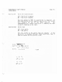
Input and Output Baud Rate
Positions 1, 2,3, 4, 5, 6
Switch positIons 1,2, and 3 are for setting the output
baud rate and posItions 4, 5, and 6 are for the Input baud
rate. Set each switch to give the baud rate as determined
by the chart below. These switches must be set properly to
assure proper operation.
Baud Rate Select Chart
Position (output)
Position (Input)
Position #7
1
2
3
4
5
OFF
ON
OFF
ON
OFF
ON
OFF
ON
OFF
OFF
ON
ON
OFF
OFF
ON
ON
6
OFF
OFF
OFF
OFF
ON
ON
ON
ON
Baud Rate
110
150
300
600
1200
2400i
4800
9600
Character Length
OFF
'iON
=8
=7
data bIts
data bIts
This swItch sets the number of data bIts in each character
for both Input and output. For most applIcations this wi I I
be 8 data bits (SwItch set "OFF").
Position #8
Number of Stop BIts
~OFF
ON
= 1 stop bit
=
2 stop bits
Set this switch for the number of stop bits you require,
both tnput and output. For most applicatIons thrs wI II be
t stop bIt (Switch set "OFF").
/~
SooperSpooler User's Manual
PagE: 3-5
Installation
.-
Porrt-y BIt-
PosIt-Ton 11-9
OFF
ON
I,
=
=
En~bleIDi~~ble
Parity bit disabled
Parity bit enabled
Set th is sw I tch to nONn
most applIcatIons do not
will normally be set
SooperSpooler wi I I output
no parity checkIng on the
PosItion #10
I f a par Ity bit
require a parity
to the nOFF"
a parIty bIt If
Input.
rs
requ Ired.
As
bIt, this swItch
pos It Ion.
The
enabled. but does
ParIty Type
OFF
ON
=
Even parIty
parity
= Odd
Set th is sw Itch to the par Ity type you requ (re.
I f the
parity bit Is disabled (the most lIkely condItion), then It
does not matter how this switch is set.
c~~ -t.~ ~P\\lb
SF\e~- r:.rJ ~~6oo ~PtvJ
OUT '
~Ab
0
\
~.c))) e,A.0~
\
;;)
oft
ON
Y
orr
IJ UTJ
5
ON
~ (;
0";
ON
.6f'\vd
Page 3-6
3.6
SooperSpooler User's ~anual
Insta I Iat Ion
Interfacing to Your Computer and Printer
When making any connectIons, be sure that your computer, printer, and
SooperSpoo Ier are turned of to
If your cab Ies are supp I Ied by your dea Ier
or by Compul Ink, you simply plug them Into the appropriate matching
connectors on the back of the unit. If you are providing your own cables,
doubte check your work to make sure all slgnal s are connected to the
correct connector pins. Connector pinout diagrams and signal descriptions
are provided In appendIx A of this manual.
The connectors are arranged 1n rna Ie-fema Ie pa Irs so that you may bypass
the SooperSpooler by simply plugging your computer and prrnter cables
together.
In fact, before you plug your cables Into your SooperSpooler,
It Is recommended that you test them by pluggIng them together and
checking for proper prInter operation.
(This only works If you are
operating In a paral lel-paral lei or a serial-serial confIguration.)
When I nsta III ng the connectors, make sure they are mated secure Iy and
completely. Improperly seated connectors are a common source of errors.
3.6.1
The Interface Problem
A severe Iack of standard r zat ron in the pr f nt£r industry has made It
almost Impossible to provide cables and/or connectors that would handle
Interconnect Ions for any reasonab Ie number of specl fie app I Icat Ions.
If
your equipment uses the standard 36 pIn Centronics type parallel
[nterf ace, you shou Id have no dI ff Icu Ities as th f s f nterf ace has become
sort of a standard In the mIcrocomputer Industry and It Is the one used In
the SooperSpoo Ier. However, there are myr Iads of other i nterf aces, both
parallel and serial, that may be completely drfferent froo any standard.
If you experi8nce problems in getting your SooperSpool8r to operate
properly, it most I ikely Is a problem with the Interface cables.
3.6.2
Paral lei Port Cables
The parallel ports use the standord 36 pin Centronics type connectors and
pinout. If your printer uses this Interface, you only need to unplug the
cab Ie from your pr Inter, Insert It Into the connector Iabe t ed "COMPUTER"
on the back of the SooperSpooler, and add a cable between the connector
labeled "PRINTER" and your printer.
A standard cable Is available from
Compul Ink for this purpose.
If your printer uses some other type of connector and/or pinout, you must
Your dea Ier Is the
use cab Ies made spec i fIca I IY for your app I Icat Ion.
best source for these cab Ies. However, 'f you des ire to bu I Id your own
cables, Compullnk will provide mating parallel connectors for the
SooperSpooler at a nominal charge.
SooperSpooler User's Manual
Insta I Iat Ion
3.0.3
~erlal
Fori
Page 3-7
cables
The opt Iona I ser Ia I ports use standard DB-25 connectors and the p r nout
You probab Iy on Iy have a 50-50
conforms to the EIA RS-232 standard.
chance that your printer pinout matches that of the SooperSpooler so It Is
very Important to be sure that al I data and handshaking signals are
properly connected.
Again, your dealer Is the best source for cables
particular to your application.
3.7
Initial Operation
WIth the configuration switches set and the cables Instal led, you are now
ready to check the operation of your SooperSpool er. PI ug Itin and turn
It on along with your computer and your printer.
It Is usually a good
Idea to press the "hard" reset button on the back of the unIt to clear any
unwanted characters that may have been erroneous Iy generated by computer
turn-on. The Buffer status Readout wi I I dIsplay "00" Indicating that the
buffer Is empty.
Press and release the Space Compression button. The Space Compression LED
shoul'd now be lit. Press and release the Page button and the Page LED
should lIght. Press each agaIn to turn them off.
Press both the Space Compression and the Page buttons simultaneously.
This will Initiate the Self Test procedure. Refer to Section 4.1.7 for a
descr Ipt Ion of th! s f unct Ion.
If you get no pr 1ntout or an Incorrect
prIntout (extra or non-exIstent Ilnefeeds), double check your cabling
and/or your confIguration switch settings.
Send severa I II nes of text from your computer to your pr r nter r n the same
fashIon you would without the SooperSpooler.
The printer should
ImmedIately begin printIng and control of your computer should return to
you before the first line Is half printed (unless you have a very fast
pr Inter). Note that the Buffer Status Readout changed from "00" to "Ot"
Indicating the presence of a to lK bytes of text In the buffer. When the
printer has completed It's job, the buffer will return to "00". AgaIn, If
your prIntout has extra or missIng line feeds, you may need to modIfy your
configuration swItch settings.
After the successful completion of these Initial tests, your SooperSpooler
Is now ready to take control of your printer, freeIng your computer to
perform activitIes more profitable or enjoyable to you.
SooperSpooler User's Manual
Operational Features
4.
4.1
Page 4-1
OPERATIONAL FEATURES
External Controls and Indicators
Fol lowIng !s a descrIption of each of the external controls and
IndIcators. Note that some of the functIons are also software enabled.
BecomIng famll iar wIth these features will help you make fUll use of the
SooperSpooler's capabilitIes.
4.1.1
Power SwItch
The power swItch Is located on the far left sIde of the front panel. ThIs
swItch controls the maIn 115YAC power Into the SooperSpooler.
TurnIng
on thIs switch also Initiates the "hard" reset sequence of events as
described rn SectIon 4.1.8.
4.1.2
Buffer Status Readout
The Buffer Status Readout dIsplays a continuously updated number that
represents the amount of Internal memory beIng currently used.
This
number actually is the 1 kilobyte block that Is currently beIng fll led or
emptied. Therefore, when the buffer Is empty, the display wI I I read "DO",
when the buffer contaIns 1 byte to 1 kilobyte of data, the dIsplay will
read "01". The dIsp lay wI II contI nue to add 1 to the count for every
addItIonal 1 kilobyte In memory.
When the buffer Is ful I, the display wll I read "16" for the 16K base model
and will read "62" If you have the memory optIon Installed.
If data Is
stIli beIng receIved wIth the buffer full, the dIsplay will
fluctuate
between the memory size and one less than the memory sIze as the
SooperSpooler wI I 1 alternately receIve and send data In one kIlobyte
blocks untIl no more data Is being received.
4.1.3
"Soft" Reset Pushbutton
The "Soft" Reset button Is located on the front panel just to the rIght of
the Buffer status Readout. PressIng and releasIng thIs button only resets
the buffer cond It Ion to empty, as Ind Icated by the Bu f fer stat us Readout
dIsplaying "00".
Whatever data that may have been In the buffer Is
no other software or hardware controllable parameters are
deleted;
ThIs Is handy for termInating an unwanted prIntout without
ch.anged.
affect! ng formatting parameters previously set up.
Page 4-2
4.1.4
SooperSpooler User's Manual
Operational Features
Space Compression Pushbutton
The Space Compression pushbutton enables the space compressfon function [n
the SooperSpooler.
ThIs functIon Is selected by pressIng and releasing
the button and Is Indicated as active by the Space CompressIon LED
direct I y above the button. When enab I ed, any group of spaces number r ng
between 1 and 127 Is compressed Into a sIngle byte. This al lows much more
efficient use of memory wIth data that contarns a slgnlftcant amount of
spaces, such as columnar documents.
The operation of thIs function Is
coop I ete I y transparent to the user except that much I ess memory I s used
when storing data with a large quantity of spaces.
This function Is
turned off by again pressing and releasIng the Space CompressIon
pushbutton.
The SooperSpooler Internally sets bit 7 high In order
space compress I on character, therefore I f you des I re to
uses any codes above 127, space compress [on must not
example of this would be the graphics characters used
manufacturers that use codes above 127.
to recognize the
spool data that
be enab I ed.
An
by some printer
The Space Compression button Is only operatIve when the buffer Is empty as
1ndlcated by a "00" reading on the Buffer Status Readout.
This functIon Is also software selectable.
Information on how to enable by software.
4.1.5
See
Section
4.2:2
for
Page Pushbutton
Pressing and releasing the Page pushbutton enables automatic document
pagination.
The selection of thIs functIon Is IndIcated by the lighting
of the Page LED located above the Page pushbutton.
When enab I ed, th I s
function formats your data Into pages using a physIcal page length and a
pr I nted I I nes per page determ I ned by va I ues stored r n the SooperSpoo I er.
These values are preset upon turn-on or "hard" reset to defaults of a page
I ength of 66 I I nes and a pr I nted I I nes per page of 62.
Therefore, when
paginatIon Is enabled using the default values, the SooperSpooler 'III II
prInt 62 lines just as they were received from your computer, but '11111
advance to the top of the next form before prJ ntl ng the next II ne.
Thl s
eliminates printing on the perforatIons of fan fold paper.
The Page button Is only operatIve when the buffer Is empty, as IndIcated
by a "00" readIng on the Buffer Status Readout.
The functIon may be
turned off by again pressing and releasing the Page pushbutton.
This function may also be software enabled, and the page length and lines
per page parameters may be changed by software.
See Section 4.2.3 for
further InformatIon on software control of pagInation.
SooperSpooler User's Manual
Opera~'onal
4.1.6
Page 4-3
Fea~ures
Single Sheets
The Single Sheets function is enabled by holding in the Page pushbutton
while turning on the SooperSpooler or while pressing the "hard" reset
button on the back of the unit.
To Indicate that the SIngle Sheets mode
has been act I vated, The Page LED wI I I f I ash unt I I the Page button Is
pressed again.
If pagJnation Is also desired, pressing the Page button
again wI I I enable this function exactly the same as If Single Sheets were
not enab I ed.
Th I s doub I e press I ng of the button must be done before any
text Is sent to the SooperSpooler.
Wh I I e I n the Sing I e Sheets mode, the SooperSpoo I er wi I I stop your pr Inter
and walt at the end of each page until the page button is pressed again.
The page LED will flash when the unit Is In this wafting state.
This
allows you to print your document on sIngle sheets of plaIn paper or
letterheads.
If the SIngle Sheets function is enabled wIthout enabling pagination, this
assumes that the host computer will be providing form feed characters to
advance to the top of the next form.
If your computer outputs multiple
line feeds for the top of form functIon, the SooperSpooler has no way to
sense that a form feed Is desired and the SIngle Sheets function wI II not
work.
The Single Sheets function Is also software selectable.
See
4.2.3 and 4.2.3.3 for InformatIon on how to enable by software.
4.1.7
Sections
Self Test
The Self Test function rs a software check of the read only memory (ROM)
and the random access memory CRAM).
Successful completion of this test Is
a good IndIcation that most functions of the SooperSpooler are operating
correctly.
This functIon Is InitIated by pressIng both the Space CompressIon and the
Page pushbuttons simultaneously.
Your prInter should Immediately print
out the fol lowing:
SOOPERSPOOLER SELF TEST
ROM VERSION (current ROM version number)
ROM TEST: PASSED
RAM TEST:
IN PROGRESS
,--/
The ROM test calculates a checksum of the total ROM and compares It to a
I f the two va I ues do not match, the ROM test
va I us stored I n the ROM.
wi II IndIcate "FAILED" (an unlikely occurence).
DurIng the RAM test, the
Buffer Status Readout wll I proceed from "11" to "88 11 rndlcatlng whIch pass
of the 8 memory test passes Is beIng perform€d. The Space CompressIon and
Page LED's wI II alternately flash IndicatIng respectIvely the write and
read portIons of the test.
SooperSpooler User's Manual
Operational Features
Page 4-4
When the RAM test
printed:
Is successfully completed,
the
fol lowing
wll I be
RAM TEST: PASSED
SELF TEST COMPLETED
If the test determInes that any of the RAM Is defectIve, the numbers of
the possibly defective Integrated circuIts are printed.
This functIon may also be software InItIated.
Information on how to enable by software.
4.1.8
See Section 4.2.8 for
"Hard" Reset Pushbutton
The Hard Reset pushbutton Is located In the lower rIght hand corner of the
back of the SooperSpoo Ier. Press Ing th Is button restores a I r parameters
to power-up cond It Ions: the Buffer Status Is set to "00", space
compressIon and pagInation are dIsabled, and al I formattIng parameters are
cleared and/or reset to the default parameters. AI I configuration switch
sett Ing s are "read" an d stored. Th Is procedu re Is f unct Iona I Iy Ident Ica I
to that performed upon turn-on.
This functIon may also be software InitIated.
Information on how to enable by software.
See Section 4.2.1 for
Page 4-5
SooperSpooler User's Manual
Operational Features
4.2
Software Controllable Features
Your SooperSpoo I er conta I ns as stan dard many funct Ions that are software
enabled or modifiable.
Some of the software controllable features are
also hardware enabled and are so Indicated as applIcable.
Each software control sequence consists of a leadln character (default=28)
fo II owed by one or more contro I characters determ I ned by the part I cu I ar
functIon being enabled or changed.
The leadln character may be software
changed to any value between 0 an 31 If a conflIct exists wlth the 'default
value of 28 (see SectIon 4.2.7>.
The word "leadln" In this manual refers
to the value assigned to this character.
The control sequence may be generated by whatever means you desire as
as you remember that the
leadln character
Is the only way
SooperSpool er can recogn I ze an contro I sequence and must precede
sequence.
I n BAS I C an contro I sequence I ead I n character might look
this:
lPR1NT O1R$(28);
'~'
long
your
each
I Ike
ThIs would be followed by whatever characters or codes that the desired
sequence requIres.
Note that each control sequence Is ended with a
semicolon;
this supresses the Iinefeed following the sequence.
For the
ease of writing this manual, al t references to the leadln character assume
that It Is the default value - If you use another value for the leadln
character, substl tute your va I ue for the va I ue of 28 as shown.
I f your
computer uses some statement other than "lPR I NT" to send text to the II ne
pr Inter, p I ease .subst I tute that statement as necessary.
A I I parameters
that must be selected by the user are shown enclosed In
brackets:
[parameterJ.
Some computers wll I not output certain values usIng the CHR$ functIon. For
examp I e, one we II known persona I computer wII I not outp ut the fo II ow I ng
values: 0, 10, 11, 12, 13.
If your equipment has thIs problem, add 128 to
any of the values used for page length, lInes per page, left margin, or
overflow Indentation. The SooperSpooler wIll subtract 128 from any values
received over 127 on these functions.
A short BASIC program lIsting Is Included at the end of thIs chapter that
wi II
help
In
setting
up
and
understandIng
the
varIous
software
controllable functions available.
AppendIx C contaIns
sequences.
a
quick
reference
sheet
of
the
software
control
Page 4-6
4.2.1
SooperSpooler User's Manual
Operational Features
"Hard" Reset
Format:
BAS 1C:
Leadln Z
LPRINT OiR${28}i"Z"i
The "Hard" Reset control sequence restores your SooperSpooler to power-up
condItion IdentIcal to pressing the "hard" reset button on the back of the
unIt (see SectIon 4.1.8L
As the first character of any data received
during the reset InItialization period wIll be lost, It Is reco","ended
that you delay sending any data to the SooperSpooler for at least one
millIsecond after InItiating "hard" reset.
4.2.2
Space Compression
Format:
BASIC:
Variables:
Leadln SeX]
LPRINT Q-lR$(28}i"S[X]"
X - "O"=Dlsable, "1"= Enable (default="O")
Example:
LPRINT Q-lR$(28};"Sl"
Enables Space Compression and I Ights front panel LED
The Space CompressIon control sequence functIons exactly as the Space
Enabling or dIsabling thIs
Compression pushbutton (see Section 4.1.4L
function wll I light or extinguish the Space Compression LED just as If the
pushbutton were pressed. This control sequence may be burled In the data
being sent to the SooperSpooler and It wll I turn space compression on and
off as des I red enab I r ng the user to space compress some port Ions of a
document and not others.
4.2.3
PagInation
Format:
BASIC:
VarIables:
Leadln P[X1][X2][X3][X4]
LPRINT Q-lR$(28}i"P[Xl][X2][X3][X4]";
Xl - Pagination
"0"=Dlsable, "l"=Enable (default="O")
X2
Header (see Section 4.2.3.1)
"O"=Dlsable, "l l1 =Enable (default=1I0")
X3
Page Numbering (see Sectlon 4.2.3.2)
"Oll=Dlsabre, "1"=Enable (default="O")
X4 - SIngle Sheets (see SectIon 4.2.3.3)
"0"=Dlsable, "l"=Enable (default="O")
Example:
LPR INT Q-lR$(28}; ~lPll1 0";
Enables Pagination, al lows prInting of a header,
performs page numberIng, does not stop after each
page. Lights Page LED.
The Poglne:rtlon control sequence functIons exactly as the Page p U $ h b u t t o n , (see Section 4.1.5).
In additIon to enablIng pagInation, thIs function
also checks to see If the Header or Page Numbering functIons are enabled.
SooperSpooler User's Manual
OperatIonal Features
Page 4-7
If either of thsSQ functIons ars QnablQd, ~nabl rng or disablIng PagInatIon
wi I I also enable or disable these functIons. ThIs Is true whether
Pagination Is enabled via the control sequence or the Page button. Single
Sheets may be enabled Independent of the pagination function.
ThIs control sequence may be burled In the data being sent to the
SooperSpooler and wI II turn pagInation on and off as desIred. Each time
pagination Is enabled or dIsabled the lIne and page counts are reset to O.
Th Is a I lows the user to reset page an d II ne counts on each of mu I tl pie
documents that mIght be stored In the buffer.
The fol lowIng four subsections describe the Header, Page NumberIng, SIngle
Sheets and Page Formatting Parameter functIons In greater detal I.
4.2.3.1
Headers
If both PagInation and the Header are enabled per sectIon 4.2.3, a header
of your choIce will be printed at the top of each page. ThIs header may
be up to 70 characters long and should be composed of printable
characters. Any characters beyond 70 are dIsregarded.
Inputting the header requIres a specIal control sequence as fol lows:
Format:
BASIC:
Variables:
Leadln H [Header] ETX
LPRINT O1R$(28)i"H[Header]"i01R$(3)i
Header - any strIng of up to 70 prIntable characters
Example:
LPRINT O1R$(28);"HSample Prlntout"iCHR$(3)i
Stores In SooperSpoolerts memory the header "Sample
PrIntout" to be printed at the top of each page If
enabled.
A header wI I I be stored unchanged In memory unt i I another header Is Input,
a "hard" reset button Is inltlated, or the SooperSpooler Is turned off.
4.2.3.2
Page Numbering
If PagInation, the Header, and Page NumberIng are enabled per sectIon
4.2.3, a page number wil I be printed at the top right corner of each page
In the form:
Page XXX
This number Is Incremented each time the paper Is advanced to the top of
the next form and Is reset to 1 each time pagInation is enabled or
dIsab Ied.
If on Iy the page number Is des Ired without a header, r nput a
null header (thIs Is the default condItIon).
In order for th Is functIon to be used, your computer must use the form
feed character In order for the SooperSpool EJr to recogn Ize that a top of
form Is desired.
Page 4-8
SooperSpooler User's Manual
Operational Features
-~,
4.2.3.3
Single Sheets
The Single Sheets function may be enabled by software per Section 4.2.3 or
by hardware per Section 4.1.6 and performs exactly the same In either
case.
Please see Section 4.1.6 for Information on the operation of the
Single Sheets function. Single Sheets may be enabled Independent of any
other function.
4.2.3.4
Page Formatting
Format:
BASIC:
Variables:
Leadln R[N1][N2][N3]
LPR I NT (}IR$ (28) ; uR"; (}IR$ ([N 1]) ; (}IR$ ([N2]) ; (}IR$ ([N3]) ;
N1 - Physical Page Length (lines)
Select 1 to 127 (default=66)
N2 - Printed Lines Per Page
Select 1 to 127 (default=62)
N3 - Right MargIn (Vertical column number)
Select 10 to 255 (default=80)
Example:
LPR I NT QiR$ (28) ; uR"; CHR$ (66) ; QiR$ (50) ; CHR$ (72) ;
Sets the page length at 66 lines, the printed lines
per page at 50, and the right margin at 72.
When pag I nation Is enab I ed, the SooperSpoo I er wIII format your data Into
pages us Ing va I ues for page length, pr I nted I I nes per page, and right
marg In that are stored In memory.
These va I ues may be Independent I y
software changed within the limits shown.
Initiating the "hard" reset
sequence or turnIng the unIt off and on again wI II reset al I values to the
default values shown.
Disabling or ena,bllng Pagination will not change
values previously stored In memory.
Note that the phys Ica I page Iength may be changed on Iy If the mu Itip Ie
line feed type of form feed Is selected (switch S1, posItion 3 Is "OFF").
Please see Section 3.5.1 for further Information.
The printed lInes per page quantity Includes two spaces for the header
and/or page numbering, If enabled.
SooperSpooler User's Manual
Operational Features
4.2.4
LIne
Page 4-9
Form~ttlng
Format:
BASIC:
Variables:
Leadin F[X][Nl][N2][N3]
LPR INT Q-1R$ (28); "FX" i Q-1R$ ([Nl]); Q-IR$ ([N2]); Q-1R$ ([N3]);
X - "O"=Oisable, "l"=Enable (default="O")
Nl
Left Margin (Vertical column number)
Select 1 to 127 (default=O)
N2
Overflow Indentation (Vertical column number)
Select 1 to 127 (default=5)
N3
Right Margin (vertIcal column number)
Select 10 to 255 (default=80)
Example:
LPRINT Q-1R$(28);"Fl"iQ-lR$(10);Q-IR$(15)iQ-lR$(70);
Enables I Ine formattIng, sets the left margin at
10, the right margIn at 70, and the overflow
Indentation at 15.
When the Line Formatting function Is enabled, the left margIn, the rIght
marg In, and the overf low 1ndentat Ion may each be Independent Iy set vIa
software. Overflow Indentation al lows the user to specify the left margin
for the port Ion of a 11 ne that sp' I Is over to the next 1Ine because the
total J Ine Is longer then the specifIed printable I rne length.
This
function Is particularly useful In making BASIC program listings easily
readable.
Pressing the "hard" reset button or turning the unIt off and on agaIn will
reset a II va Iues to the defau It va Iues shown.
01 sab II ng or enab 11 ng
Pagination wll I not change values previously stored In memory.
4.2.5
'---...
Change ConfiguratIon SwItch Selected Items
Format:
BASIC:
Variables:
Leadln C[X1][X2][X3]
LPRINT Q-1R$(28)i"C[Xl][X2][X3]";
Xl - Output port
"O"=Para I Ie I port, "1 "=Ser Ia I port
X2 - Printer lIne end requirement
"O"=CR only, "l"=CR/LF
X3 - PrInter form feed requirement
"O"=ASCII FF, "l"=Multlple line feeds
Example:
LPR INT Q-IR$ (28); "Cll 0";
Selects the serial output port, sends a carrIage
return/line feed at the end of each line, and uses
the ASCI I form feed character for the top of form
functIon.
Three of the Items se Iected by the conf Igurat i on sw Itches may be changed
by software. ThIs allows the user to control more than one printer with
the SooperSpooler by switching the output between the paral lei output port
and the serial output port (this assumes the serial option Is Installed).
PressIng the "hard" reset button or turning the unit off and on agaIn wll I
reset all values to the values determined by the confIguratIon switches.
See Section 3.5 for further InformatIon on the confIguratIon switch
functIons.
Page 4-10
4.2.6
SooperSpooler Usor's Manual
OperatIonal Features
RedefIne FF Character
Format:
BASIC:
Variables:
Leadin D[N1][N2]
LPR INT a-JR$( 28); "D"; a-JR$ ([N1]); CHR$([N2]);
N1 - Input form feed character
Select 0 to 31 (default=12)
N2 - Output form feed character
Select 0 to 31 (default=12)
Example:
LPR INT a-JR$ (28) ; liD"; OiR$ (7) ; OiR$ (8) ;
Sets the Input form feed character to decimal 7
and the output form feed character to decimal 8
Some pr r nters and computers use a form feed character other than the
standard ASCII FF (12 dec ima I ).
Others may use code 12 for sane other
function.
ThIs function allows the user to re-specffy the form feed
character In order to circumvent this confl let. PressIng the IIhard" reset
button or turnIng the unit off and on again wll I reset these values to the
default values shown.
4.2.7
Redefine Lead!n Character
Format:
BASIC:
Variable:
Leadln [N]
LPRINT OiR$(28);OiR$(N);
N - New leadln character
Select 0 to 31 decImal (default=28)
Example:
LPRINT OiR$(28);OiR$(2};
Changes the leadln character from 28 decimal to
2 decimal
ThIs function al lows the leadln character to be changed from decImal 28 to
any value between 0 and 31. This eliminates confl lets caused by a system
that uses 28 for another funct Ion. Press Ing the "hard" reset button or
turnIng the unit off and on again wi I I reset thIs value to 28.
4.2.8
Self Test Routine
Format:
BASIC:
Leadin T
LPRINT OiR$(28};"T"
ThIs control sequence InItiates the Self Test Routine.
Information on the Self Test Routine, see Section 4.1.7.
For
full
SooperSpooler User's Manual
Operational Features
4.3
Page 4-11
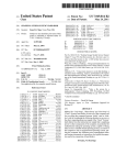
Setup Program ListIng
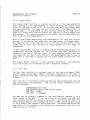
Fol lowIng's a program lIstIng written In MIcrosoft BASIC that wll I
greatly aid In settIng the software controllable features of your
SooperSpooler.
10 CLS: CLEAR 200
:REM CLEAR SCREEN; 200 BYTES OF STRING SPACE
20 INPUT "DO YOU WANT TO Q-lANGE THE LEADIN Q-lARACTER"; A$
30 IF LEFT$(A$,l )="N" THEN LI$ = OiR$(28): GOTO 70
40 INPUT "ENTER ORDINAL VALUE OF NEW LEADIN OiARACTER (0 TO 31)"; LI
50 IF LI<O OR LI>31 THEN GOTO 40 ELSE LI$ = OiR$(LI)
60 LPRINT Q-lR$(2S); LI$
:REM Q-lANGE TO NEW LEADIN Q-lARACTER
70 FI$ ; ; Q-lR$(12)
:REM FORM FEED (INPUT) CHARACTER
80 FF$ = Q-lR$(12)
:REM FORM FEED (OUTPUT) Q-lARACTER
90 SC$ == "011
:REM SPACE COMPRESSION OFF
100 PG$ = "0"
:REM PAGINATION OFF
110 PH $ = "0"
: REM PR INT HEADER OFF
120 PN$ ; ; "0"
:REM PAGE NUMBERING OFF
130 PS$ = "011
:REM SINGLE SHEETS FUNCTION OFF
140 PL$ = Q-lR$(66)
:REM PAGE LENGTH ;;;; 66 LINES
150 LP$ = Q-lR$(62)
:REM PRINT 62 LINES PER PAGE
160 CLS ; ; OiR$(SO)
:REM SO Q-lARACTERS PER LINE
170 H$ ; ; ""
:REM NULL HEADER
180 F$ ; ; "0"
: REM FORMAn ING OFF
190 LM$ == Q-lR$(O)
:REM LEFT ~~RGIN == 0
200 01$ ; ; CHR$(5)
:REM OVERFLOW INDENTATION;;;; 5
210 OP$ ; ; "0"
:REM OUTPUT TO PARALLEL PORT
220 PA$ -:; "0"
:REM PRINTER REQUIRES CARRIAGE RETURN ONLY
230 PF$ == "0"
: REM OUTPUT FORM FEED TO ADVANCE TO TOP OF FORM
240 CLS
:REM CLEAR SCREEN
250 PRINT "c - Q-lANGE DIP SWITQ-l SELECTABLE ITEMS"
260 PRINT "D - DEFINE FORM FEED OiARACTERS"
270 PRINT "F - FORMAnlNG PARAMETERS"
2S0 PRINT IIp - PAGINATION"
290 PRINT "s - SPACE COMPRESSION: ";: T$=SC$: GOSUB 1070
300 PRINT "T - START SELF TEST AND END PROGRAM"
310 PRINT "Z - RESET TO POWER UP PARAMETERS": PRINT
320 PRINT "0 - OUTPUT PARAMETERS TO SOOPERSPOOLER"
330 PRINT "X - END PROGRAM"
340 GOSUB 1120
350 IF A$=IIC" THEN GOTO 530
360 IF A$="D" THEN GOTO 6S0
370 IF A$="F" THEN GOTO 760
380 IF A$="PI1 THEN GOTO 880
390 IF A$="S" THEN T$=SC$: GOSUB 1090: SC$=T$: GOTO 240
400 IF A$="T" THEN LPRINT LI$;"T": END
410 IF A$=IIZ" THEN LPRINT LI$;"Z": GOTO 10
420 IF A$="X" THEN END
430 IF A$<>"O" THEN GOTO 240
Page 4-12
440
450
460
470
480
490
500
510
520
530
540
550
560
570
580
590
600
610
620
630
640
650
660
670
680
690
700
710
720
730
740
750·
760
770
780
790
800
810
820
830
840
850
860
870
880
SooperSpooler User's Manual
OperatIonal Features
REM OUTPUT ALL PARAMETERS TO SOOPERSPOOLER
LPRINT LIS; "0"; Q-1R$(ASC(FIS)+128); Q-lR$(ASC(FF$)+128);
LPRINT Ll $; "S"; SCSi
LPRINT LIS; "P"; PGS; PHS; PNS; PSS;
LPRINT LI$; "R"; Q-1RS(ASC(PL$)+128); Q-lRS(ASC(LP$)+128); CL$;
LPRINT LI$; "H"i HS; Q-lR$(3);
LPRINT LIS; "F"; F$; Q-lRS(ASC(LMS)+128); Q-lRS(ASC(01$)+128); CL$;
LPRINT LI$; "C"i OPt; PAS; PF$
GOTO 240
CLS: PRINT"Q-lANGE DIP SWITQ-l SELECTABLE ITEMS": PRINT
PRINT "1 - OUTPUT TO: ";
IF OPS="O" THEN PRINT "PARALLEL"; ELSE PRINT "SERIAL";
PR INT " PORT"
PRINT "2 - PRINTER REQUIRES: ";
IF PA$="O" T}jEN PRINT "CARRIAGE RETURN ONLY"
ELSE PRINT "CARRIAGE RETURN + LINE FEED"
PR INT "3 - OUTPUT: ";
IF PF$="O" THEN PRINT "FORM FEED"; ELSE PRINT "MULTIPLE LINE FEEDS";
PRINT" TO ADVANCE PAPER"
GOSUB 1110
IF A$="O" T}jEN GOTO 240
IF A$="1" THEN T$=OP$: GOSUB 1090: OP$=T$: GOTO 530
IF AS="2" T}jEN TS=PA$: GOSUB 1090: PAS=TS: GOTO 530
IF A$="3" THEN T$=PF$: GOSUB 1090: PF$=T$
GOTO 530
CLS: PRINT IIDEFINE FORM FEED INPUT AND OUTPUT Q-lARACTERS": PRINT
PRINT "1 - FF (INPUT) (0 TO 31. DEFAULT = 3):"; ASC(FI$)
PRINT "2 - FF <OUTPUT> (0 TO 31.• DEFAULT = 12) :"; ASC(FF$)
GOSUB 1110
IF A$="O" THEN GOTO 240
IF A$="l" THEN INPUT "ENTER VALUE FOR FF (INPUT> (0 TO 31)"; FI
: FI$=Q-lR$(F I)
IF A$="2" THEN INPUT "ENTER VALUE FOR FF <OUTPUT> (0 TO 31)"; FF
: FF$=Q-lR$(FF)
GOTO 680
CLS: PRINT "FORMATIING PARAMETERSlI: PRINT
PRINT "1 - FORMATIING: ";: T$=F$: GOSUB 1070
PRINT "2 - LEFT MARGIN (0 TO 127. DEFAULT = 0): "; ASC(LM$)
PRINT "3 - OVERFLOW INDENTATION (0 TO 127. DEFAULT = 5): "; ASC(OI$)
PRINT "4 - RIGHT MARGIN (10 TO 255. DEFAULT = 80): "; ASC(CL$)
GOSUB 1110
IF A$="O" THEN GOTO 240
IF A$= 1I 1" THEN T$=F$ : GOSUB 1090: F$=T$
IF A$:"2" THEN INPUT IIENTER LEFT MARGIN (0 TO 127)"; LM: LM$=Q-lR$(LM)
IF A$="3" T}jEN INPUT IlENTER OVERFLOW INDENTATION (0 TO 127)";01
: 01 $=Q-lR$(QI)
IF A$=1l4 1l THEN INPUT "ENTER RIGHT MARGIN (10 TO 255)";CL: CL$=Q-lR$(CU
GOTO 760
CLS: PRINT "1 - PAGINATION: ";: T$=PG$: GOSUB 1070
890 PRINT "2 - HEADER:
"~:
T$-PH$; GOSUB 1070
SooperSpooler User's Manual
OperatIonal Features
Page 4-13
900 PRINT "3 - PAGE NUMBERING: n;: T$=FN$: GOSUB 1070
910 PRINT "4 - SINGLE SHEETS: ";: T$~PS$: GOSUB 1070
920 PRINT "5 - PAGE LENGTH (1 TO 127, DEFAULT = 66): If; ASCCPL$)
930 PRINT "6 - LINES PER PAGE (1 TO 127, DEFAULT = 62): If; ASC(LP$)
940 PRINT "7 - O1ARACTERS PER LINE (10 TO 255, DEFAULT = 80): ";ASC(CL$)
950 PRINT "8 - ENTER NEW HEADER"
960 GOSUB 1110
970 IF A$="O" THEN GOTO 240
980 IF A$="l" THEN T$=PG$: GOSUB 1090: PG$=T$
990 IF A$="2" THEN T$=PH$: GOSUB 1090: PH$=T$
1000 IF A$="3" THEN T$=PN$: GOSUB 1090: PN$=T$
1010 IF A$="4" THEN T$=PS$: GOSUB 1090: PS$=T$
1020 IF A$="5" THEN INPUT "PAGE LENGTH, 1 TO 127 LINES";PL: PL$=01R$(PU
1030 IF A$="6" THEN INPUT "1 TO 127 LINES PER PAGE"; LP: LP$=Q-IR$(LP)
1040 IF A$="7" THEN INPUT "10 TO 255 Q-IARACTERS PER LINE"; CL: CL$=Q-IR$(CU
1050 IF A$="8 11 THEN PR INT H$: INPUT "ENTER NEW HEADER "; H$
1060 GOTO 880
1070 IF T$="O" THEN PRINT "DISABLED" ELSE PRINT "ENABLED"
1080 RETIJ RN
1090 IF T$="O" THEN T$="1" ELSE T$="O"
1100 .RETURN
1110 PRINT: PRINT "0 - RETURN TO MAIN MENU"
1120 PRINT: INPUT "ENTER DESIRED CODE"; A$
1130 RETURN
Page A-1
SooperSpooler Users Manual
Paral lei Connector Pinout
PARALLEL-INPUT
SIGNAL
PIN
1
2
3
4
5
6
7
8
9
10
11
12
13
14
16
17
30
32
RETURN
PIN
19
20
21
22
23
24
25
26
27
28
29
SIGNAL
NAME
STROBE*
DATA 1
DATA 2
DATA 3
DATA 4
DATA 5
DATA 6
DATA 7
DATA 8
ACKNLG*
BUSY
PAPER EMPTY
SELECT
GND
GND
CHASSIS
GND
FAULT*
C~~~£CIQB
SIGNAL
SOURCE
Input DevIce
"
"
"
"
"
"
"
"
SooperSpooler
"
"
"
"
II
"
"
"
PINOUT
SIGNAL
FUblcrlON
Data strobe pulse
Data bit 0
Data bit 1
Data bIt 2
Data bIt 3
Data bit 4
Data bit 5
Data bIt 6
Data bIt 7
Acknowledge of data receIved
Low when spooler ready for data
None - Held low by SooperSpooler
None - Held high by SooperSpooler
Signal ground
Signal ground
ChassIs ground
Signal ground
None - Held hIgh by SooperSpooler
PARALLEL-DUTPUT CONNECTOR PINOUT
SIGNAL
PIN
1
2
3
4
5
6
7
8
9
11
12
14
16
17
30
32
/
NOTE:
RETURN
PIN
19
20
21
22
23
24
25
26
27
29
SIGNAL
NAME
STROBE*
DATA 1
DATA 2
DATA 3
DATA 4
DATA 5
DATA 6
DATA 7
DATA 8
BUSY
PAPER EMPTY
GND
GND
CHASSIS
GND
FAULT*
SIGNAL
SOURCE
SooperSpooler
"
"
"
"
"
"
"
"
Output Device
"
SooperSpooler
II
II
"
Output DevIce
SIGNAL
FUblCTION
Data Strobe pulse
Data bIt 0
Data bit 1
Data bit 2
Data bit 3
Data bIt 4
Data bIt 5
Data bIt 6
Data bIt 7
Low when prInter ready for data
High when printer Is out of paper
Signal ground
Signal ground
Chassis ground
Signal ground
Low IndIcates printer fault
Any pins not specifIcally listed are not connected In the SooperSpooler.
See the back sfde of this page for a lIst of mating connectors.
SooperSpooler User's Manual
Mating Connectors
Page A-2
The fol lowIng Is a lIst of some connectors that mate with the paral lei Input and
output connectors on the SooperSpooler prlr.ter Interface.
parallel Input from Computer
Connector descrIption: 36-posltlon ribbon-type plug, bal
J
lock
Manufacturer
part Number
J&s~rml
AMP
552931-1
InsulatIon dIsplacIng contacts, 28 AWG
flat rrbbon cable.
AMP
552274-1
*
InsulatIon dIsplacIng contacts, 24 AWG
round cable.
AMP
552470-1
*
Insulation dlsplactng contacts, 26-28
AWG round cable.
AMPHENOL
57-30360
on lapp I fcat Ion
Solder ta II contacts, 22-30 AWG round
cable.
Parallel Output to Printer
COnnector descriptIon: 36-posftlon ribbon-type receptacle, screw lock.
NU~£
Manufacturer
Part
AMP
552834-1
AMP
2-552275-1
Descrlptlon/appllcatIon
InsulatIon displacIng contacts, 28 AWG
flat rIbbon cable.
* InsulatIon dIsplacing contacts, 24 AWG
round cable.
AMP
2-552475-1
AMPHENOL
57-60360
*
*
InsulatIon dIsplacing contacts, 26-28
AWG round cable.
Sol der tall contacts, 22-28 AWG round
cable.
These connectors also require a straIn rei lef cover as fol lows:
Mg~~
Egrj Number
Appllcatron
AMP
552073-1
552073-5
552073-6
Cable dIameter
Cable dIameter
Cable dIameter
=
=
=
0.290 to 0.340 in.
0.360 to 0.430 In.
0.430 to 0.500 in.
A-3
SOOPERSPOOLER USERS MANUAL
PARALLEL PORT TIMING DIAGRAMS.
PARALLEL INPUT PORT TIMING
DATA
INPUT
0-7
J 1.0JjS
~ MIN.
STROBE
INPUT
L
r--
~ l.OVS
~ MIN.
\
~ 1.0JjS
~ MIN.
L
r--
I
L
I
. - - - - - - - - - 1 1 1 - - 1- _
BUSY
OUTPUT
_ _ _ _ _ _- . J
L.......-
/
~
lS- 37S VS
_
---~
r-
23JjS
--1
ACKNlG
OUTPUT
PARALLEL OUTPUT PORT TIM ING
BUSY
INPUT
~i----15JjS MIN.--'
DATA
OUTPUT
STROBE
OUTPUT
\
r--
I
2.0 vS
-4
Page A-4
SooperSpooler User's Manual
Serial Connector Pinout
SERIAL INPUT CONNECTOR PINQUI
Type OB-25S (socket)
SIGNAL
SIGNAL
SIGNAL
SIGNAL
.....JPL....JIL..LJN'--_~SQ.>.<JUR...",C""'E~
1
2
3
4
6
7
20
FG
TO
RD
RTS
DSR
SG
DTR
SooperSpooler
Input DevIce
SooperSpooler
Input Device
SooperSpooler
~F.JJ.UuN,C""-TL.JI-"'O=N
_
Chassis ground
Data output from SooperSpooler
Data from Input device
Request to Send - Held hIgh (on)
Ready line from Input device
SIgnal ground
Ready line from SooperSpooler
SER IAL OUTPUT CONNECTOR..PJltOllI
Type OB-25P (plug)
SIGNAL
PIN
1
2
3
5
6
7
20
NOTE:
SIGNAL
~AME
FG
TO
RD
CTS
OSR
SG
DTR
SIGNAL
SOURCE
Output Device
SooperSpooler
"
"
Output Device
SIGNAL
FUNQ.LOlL
Chassis ground
Data from output device
Data output from SooperSpooler
Clear to Send - Held high (on)
Ready I rne from SooperSpooler
Signal ground
Ready lIne from output device
Any prns not specifically listed are not connected In the SooperSpooler.
Page B-1
SooperSpooler Users Manual
AppendIx B
CONTROL SEQUENCE QUICK REFERENCE CHART
Note:
Each control sequence must be preceeded by the leadln code,
ASCI I FS = 28 decImal = 1C hex.
FUNCTION
CONTROL SEQUENCE
SPACE COMPRESSION.
..................
"O"=Dlsabled, "1"=Enabled (default=IO")
.
"SX"
I
- - - __ - __ - - - - - - - - _I
PAG INAT ION • • • • • • • • • • • • • • • • . . • . • • . • • . . • "PXXXX"
1111
"0"=Dlsabled, "l"=Enabled (default="O")
HEADER: "O"=Dlsabled, "1"=Enabled (default="0")
PAGE NUMBERING: "O"=Dlsabled, "l"=Enabled (DEFAULT="O")
SINGLE SHEETS: "O"=Disabled, "1 11 =Enabled (default=1I0")
II II
III
II
I
PAGE PARAMETEB.S. . • . • • • • • • • • • . . . • • • • . • • • IIR" , n1, n2, n3
I
nl = PAGE LENGTH, LINES (1-127) (default=66)
n2 = LINES PER PAGE (1-127) (default=62)
n3 = RIGHT MARGIN (10-255) (default=80)
I
I
I
I
,
INPUT HEAPER
.IIH",HEADER,ETX
FORMATTING.
. .IIFX",n1,n2,n3
I I I I
I I I I
I I I
I I
I
1I0"=DIsabled, "1"=Enabled (default=IO")
nl = LEFT MARGIN (1-127) (default=O)
n2 = OVERFLOW INDENTATION (1-127) (default=5)
n3 = RIGHT MARGIN (10-255) (default=80)
CHANGE PIP SW IICH SELECTABLE ITEMS . • . • • • . . • • • . • • . • •"CXXX"
III
OUTPUT: "O"=Parallel port, "1"=Serial port
PRINTER REQUIRES: "O"=CR only, "l"=CR/LF at end of I rne
OUTPUT: "O"=ASCI f FF, 1I1"=Multrple Line Feeds
DEE I NE ..
II
•
•
•
•
..
•
..
..
•
..
•
•
•
,.
..
•
..
..
•
•
..
..
..
III
II
I
..
•
..
"0 n , n 1,. n2
•
I
n1
n2
=
=
form feed character (Input) (default=12)
form feed character (output) (default=12)
I
.
START SELF TEST PROCEDURE.
• "Tlt
RESTORE POWER UP DEFAULT PARAMETERS.
. "Z"
I
I
LEAPIN CHARACTER (Default 28) may by changed by sendIng the current leadln
character followed by the new leadln character (0 to 31).
Page C-1
SooperSpooler User's Manual
Appendix C
CONFIGURATION SWITCHES QUICK REFERENCE CHART
Primary Configuration Switches
Sl-l
FUNCTION
HandshakIng
Sl-2
Output Port
Sl-3
PagInation
Sl-4
Input LF Type
Sl-5
Output LF Type
SW IIQ-!
SETTINGS
ON - ETX/ACK Serial handshaking
OFF - XON/XOFF & Hardware serIal handshaking
ON - Output to paral lei port
OFF - Output to serial port
ON - Output form feed to advance paper
OFF - Output multiple line feeds
ON - Carriage return only at end of line
OFF - Carriage return & line feed at end of line
ON - Carrrage return only to advance paper
OFF - Carriage return & lIne feed to advance paper
Optional Serial Board Configuration Switches
.
'--...-
SWllOi
S2-1
S2-2
S2-3
S2-4
S2-5
S2-6
S2-7
FUNCTION
Input Baud Rate
Output
S2-8
Stop Bits
S2-9
ParIty BIt
S2-10
Parity Type
"
"
Baud
SETTINGS
See chart below
"
u
Rate
"
II
"
"
II
Character Length
OFF - 8 Data bits
ON - 7 Data bits
OFF - 1 stop bit
ON - 2 Stop bits
OFF
Parity bIt disabled
ON - ParIty bIt enabled
OFF - Even parity
ON - Odd ParIty
-
Baud Rate Select Chart
Position (output)
Position ( Input>
----./
1
2
3
4
5
6
OFF
ON
OFF
ON
OFF
ON
OFF
ON
OFF
OFF
ON
ON
OFF
OFF
ON
ON
OFF
OFF
OFF
OFF
ON
ON
ON
ON
Baud Rate
'10
150
300
600
1200
2400
4800
9600
Page 1-1
SooperSpooler User's Manual
Index
Base model
............................................................
Memory
.. ..
..
Input/output confIguratIon
Baud rates, ser Ia I r nterface ....................................................................... 3-4,
Buffer Status dIsplay ..........................................................
2-1
2-1
C-1
4-1
ConfIguratIon swItches
CarrIage return / lIne feed ........................................................................
......................................
Default prInter output
Form feed output
Reference chart
SerIal baud rate selectIon
SerIal character length ....................................................................
Ser I a I par r ty
Serial handshakIng protocol
Serral stop bIts ....................................................................... "
.
Software confIguratIon alteratIon ............. "
.
Control sequences ................................................................................ 4-5,
3-3
3-2
3-3
C-1
3-4
3-4
3-5
3-2
3-4
4-9
B-1
. ...... ........
. . . . . . . . . . . . . . . . . . . . . . . . . . . . . . . . . . . . . . . . . . . . . . . . . . . . . . . . . . . . . . . . . . . . . . . 41
...................................
I
"
DC1/DC3 serIal handshaking protocol
ETX/ACK serIal handshaking protocol
.
2-6, 3-2
.....................
II
.
2-6, 3-2
Form feed
Control sequence to change characters
Default characters
Form length •.•••..••
Fuse
GroundIng requIrements
4-10
4-10
4-8
3-1
................................................ 3-1
Header
Enable and dIsable
Input
4-6
.4-7
..................................
Leadl n character
Control sequence
" "
Default character
"
LIne formattIng
Description
Left margin
Overflow IndentatIon
RIght margIn " " "
" "
...... .... .. ..
.
Memory expansIon optIon
Memory
"
"
""
""
.
"
"
"
"
. . ." .. ..
"
"
" " ""
" "
"
"
" "
"
" "
.
" "
""
"
"
"
.
" "
" " "
" "
.. . . 4-5,
. . 4-10
4-10
"" "" "
" "
"
"
.. . .
"
"
.
" "
" ""
"
.
" "
"
..
4-9
4-9
4-9
4-9
2-1
2-1
Page 1-2
SooperSpooler User's Manual
Index
Page LED IndIcator
4-2,
PaginatIon
Contro I sequence ••••.•.
Header enable / dIsable
Header Input
Page numbering
Page pushbutton .....................................................
Single sheets
4-3, 4-6,
Pagination parameters
................................................
Characters per lIne
Default values
Form length
LInes per page
Paral lei Interface
Cables
Connectors •.•.•••
3-6,
Input data rate
Interfacing .............................................................................
Operation ........................................................................
PInout ..........................................................................
Printer status I (nes .................................................. 2-5,
SIgnal descrIptIon
2-4, A-1,
.
SIgnal timing ............ "
SImultaneous Input wIth serIal port
•••••••••••••••••••••••••••••••••
••
....
I
••••
'II
••••••••
\II
......
'II
••••••
••••••••••••••••••••••••••••
'II
•
III
'II
••
'II
•••••••
"
'II
II
• • • • • • • • • • • • 'I
••••••••••••••••••••
••••••••••••••
'II
••••••
II
II
••
.............................................
••
I
••••
•••••••••••••
•••••••••
...
I
'II
'II
••
'II
•••••
III
•
III
•••••••••••
'II
•••••••••••••••••••••
'II
III
II
'II
••
'II
11
III
.
.
..
...........................................
Power requ I rements •
Power swItch
'II
.
...............................................
. . . . . . . . . . . . . . . . . . . . . . . . . . . . . . . . . . . . . . . . . . . . . . . . . . . . . . . . . . . . . . . . . . . III
.....
4-3
4-6
4-6
4-7
4-6
4-2
4-8
4-8
4-8
4-8
4-8
3-6
A-2
2-4
3-6
2-4
A-1
A-1
A-3
A-3
2-6
3-1
4-1
Reset push buttons
.................................................. "
. 4-4
"Hard" reset
"Soft" reset ...................................................................... 4-1
Reset control sequence .......................................................... 4-6
Self test
Control sequence
4-10
Enabling by Space CompressIon and Page swItches
3-7, 4-3
Output ................................................................................... 4-3
Serial Interface
.............................................................. 3-4, C-1
Baud rates
3-7
Cab Ies ..............................................................................
"
. 2-5, 3-2
Handshaking
Interfacing •..............••
2-5
Simultaneous Input wIth paral lei port
2-6
Srngle sheets mode
DescriptIon
4-3
Page pushbutton
4-3
PagInation control sequence
4-6, 4-8
..........
SooperSpooler User's Manual
Index
Space Compression
Control sequence
DescriptIon ••.••.
Pushbutton •••••••
Space compression LED Ind' cator
SpecIficatIons .......................... ..:
Theory of operation
Page 1-3
4-6
...............
.
....................................................
XON/XOFF serral handshaking protocol
4-2
4-2
4-2
2-7
2-1
2-6, 3-2