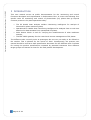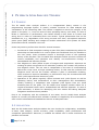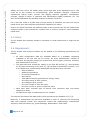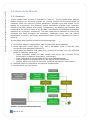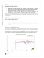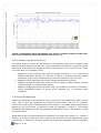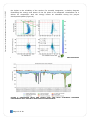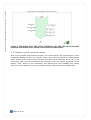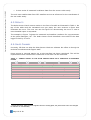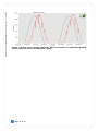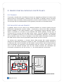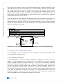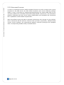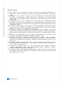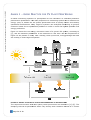
1
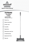
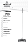
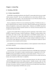
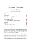
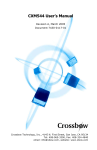
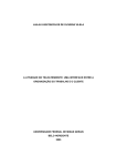
WP4 Deliverable 4.6
User Manual for Central Monitoring and Control functions
Achim Woyte, Karel De Brabandere, Babacar Sarr,
Sarr
Filip Andrén, Thomas Strasser, Johannes Stöckl
3E, AIT
31/10/2015 – Final version
Checked by Johannes Stöckl, Karel De Brabandere, Geert Palmers
This project has received funding from
rom the European Union’s Seventh Framework Programme for research, technological
development and demonstration
ation under grant agreement No 308991.
User manual for central monitoring and control functions – 31/10/2015
USER MANUAL FOR CENTRAL MONITORING
AND CONTROL FUNCTIONS
Tools for Monitoring and Control – D4.6
CONTENTS
SUMMARY. ......................................................................................................... 4
1
INTRODUCTION........................................................................................ 6
2
PV HEALTH SCAN ANALYSIS TOOLBOX ............................................................ 7
2.1
PURPOSE ............................................................................................... 7
2.2
APPLICATION .......................................................................................... 7
2.3
SCOPE .................................................................................................. 8
2.4
REQUIREMENTS ....................................................................................... 8
2.5
HEALTH SCAN PROCESS ............................................................................. 9
2.5.1
APPROACH ............................................................................................. 9
2.5.2
DATA INTEGRITY CHECK ........................................................................... 10
2.5.3
ON-SITE SENSOR DATA CHECK................................................................... 10
2.5.4
PLANT PERFORMANCE CHECK ..................................................................... 10
2.5.5
CURRENT AND VOLTAGE CHECK .................................................................. 11
2.5.6
LOSS ATTRIBUTION................................................................................. 11
2.5.7
IDENTIFY FAULTS AND ROOT CAUSES ............................................................. 13
3
OPERATIONAL PV HEALTH SCAN ................................................................. 14
3.1
PURPOSE ............................................................................................. 14
3.2
SCOPE ................................................................................................ 15
3.3
REQUIREMENTS ..................................................................................... 15
3.4
USER INTERFACE ................................................................................... 15
3.5
RESULTS ............................................................................................. 15
3.6
SALES CHANNEL .................................................................................... 16
4
SOLAR SENSOR CHECK ............................................................................ 17
4.1
PURPOSE ............................................................................................. 17
4.2
SCOPE ................................................................................................ 17
4.3
REQUIREMENTS ..................................................................................... 17
4.4
USER INTERFACE ................................................................................... 17
4.5
RESULTS ............................................................................................. 18
4.6
SALES CHANNEL .................................................................................... 18
5
REMOTE CONTROL INTERFACE FOR PV PLANTS ................................................. 20
5.1
PURPOSE ............................................................................................. 20
5.2
ARCHITECTURE AND CONCEPT .................................................................... 20
5.3
PROTOTYPICAL IMPLEMENTATION ................................................................. 21
5.3.1
HARDWARE PLATFORM ............................................................................. 21
5.3.2
SOFTWARE PLATFORM .............................................................................. 22
REFERENCES .................................................................................................... 23
ANNEX 1 – GOOD PRACTICE FOR PV PLANT MONITORING ............................................... 24
ANNEX 2 – PERFORMANCE INDICATORS ..................................................................... 26
PERFORMANCE RATIO .......................................................................................... 26
Page 2 of 29
User manual for central monitoring and control functions – 31/10/2015
AVAILABILITY INDICATORS .................................................................................... 27
TEMPERATURE CORRECTED PERFORMANCE RATIO........................................................... 28
ENERGY PERFORMANCE INDEX ................................................................................ 28
Page 3 of 29
User manual for central monitoring and control functions – 31/10/2015
SUMMARY.
The present document serves as preliminary user manual for the central monitoring and
control features developed and implemented within Performance Plus. It covers the
following four specific tools for monitoring and control of photovoltaic (PV) plants that go
beyond common practice in PV plant operations today:
•
•
•
•
The PV Health Scan analysis toolbox: Monitoring intelligence for analysis of
historical PV plant monitoring data,
Operational PV Health Scan: Monitoring intelligence for analysis close to real time
based on PV data streams from operational PV plants,
Solar Sensor Check: A tool for verifying the measurements of solar irradiance
sensors,
The IEC 61850 gateway for the control and remote management of PV plants.
The different tools currently exist as prototypes but are not yet ready to be offered to
the market. This is planned for the course of 2016. Consequently, the present user
manual should be read as a draft specification document for the different tools. It allows
for having the product specifications reviewed by potential customers from different
target groups and iterate on them for the final product development.
The PV Health Scan analysis toolbox is a computational library. It mainly contains
functions for data analysis and visualisation of PV monitoring data. The toolbox is applied
to check the integrity of PV plants in the past until today. In case of faults or reductions
in performance, the toolbox allows to drill down to inverter and string level in order to
understand their root causes. Due to its complexity and the multitude of use cases, the
PV Health Scan analysis toolbox is currently not offered as a software. Instead it is
applied by 3E’s consultants to offer a semi-automated and standardized service at
adequate costs. The document further describes user stories and data requirements. It
then details the process steps for a semi-automated analysis with the toolbox.
The operational PV Health Scan is a computational tool to be used along with an
operational monitoring platform. It automatically runs through the process steps for the
PV Health Scan analysis toolbox. The results are then interpreted by the computer.
The operational PV Health Scan detects deviations from the expected performance and
availability by means of parametric models of the PV plant’s components and the
variation of their model parameters over time. It then returns recommendations on the
most probable root causes for the deviations.
The operational PV Health Scan is offered to PV asset managers and PV operation and
maintenance (O&M) contractors. It is made available as a scan on request and as
subscription for periodic and automatic execution within the monitoring tool of the
customer.
The Solar Sensor Check is a computational tool. It is applied to check the integrity of
solar irradiance sensors based on measurements and indicate if their measurements are
wrong or imprecise. As such it is a precondition to the operational PV Health Scan that
also has business value on its own.
Page 4 of 29
User manual for central monitoring and control functions – 31/10/2015
The Solar Sensor Check detects the most important faults and imprecisions based on
measurements. It then returns recommendations on the most probable root causes.
The Remote Control Interface for PV plants has been developed to introduce a
standard-compliant and open source-based environment together with a low cost
controller platform for upgrading off-the-shelf PV inverts with Smart Grid functions.
Page 5 of 29
User manual for central monitoring and control functions – 31/10/2015
1 INTRODUCTION
This user manual serves as public documentation for the monitoring and control
functions developed and implemented in Performance Plus. It covers the following four
specific tools for monitoring and control of photovoltaic (PV) plants that go beyond
common practice in PV plant operations today:
•
•
•
•
The PV Health Scan analysis toolbox: Monitoring intelligence for analysis of
historical PV plant monitoring data,
Operational PV Health Scan: Monitoring intelligence for analysis close to real time
based on PV data streams from operational PV plants,
Solar Sensor Check: A tool for verifying the measurements of solar irradiance
sensors,
The IEC 61850 gateway for the control and remote management of PV plants.
The different tools currently exist as prototypes but are not yet ready to be offered to
the market. This is planned for the course of 2016. Consequently, the present user
manual should be read as a draft specification document for the different tools. It allows
for having the product specifications reviewed by potential customers from different
target groups and iterate on them for the final product development.
Page 6 of 29
User manual for central monitoring and control functions – 31/10/2015
2 PV HEALTH SCAN ANALYSIS TOOLBOX
2.1 PURPOSE
The PV Health Scan analysis toolbox is a computational library written in the
programming language Python. It mainly contains functions for data analysis and
visualisation of PV monitoring data. The toolbox is applied to check the integrity of PV
plants in the past, i.e., from the start of their operating history until today. In case of
faults or reductions in performance, the toolbox allows to drill down to inverter and
string level in order to understand their root causes. Typical phenomena that can be
identified are, e.g., degradation of PV string currents over time, sub-optimal maximum
power point (MPP) tracking and outages of smaller subsections of PV plants. All these
phenomena can be evaluated over time.
Users may want to perform this check for several reasons:
•
•
•
Provisional or final acceptance testing as part of PV plant commissioning when the
ownership and warranties for a new PV plant are transferred from the installer to
the new owner: these occasions require a thorough review of the operating
history of the PV plant. The PV Health Scan analysis toolbox serves to confirm the
correct installation and operation and identify non-conformities through a
standardized and efficient process.
Due diligence on older plants as part of mergers and acquisitions: whenever an
existing PV plant is acquired on the secondary market, the investor will perform a
due diligence check. The use case is comparable to the case of commissioning
above but it may cover a longer operating history. In this case the technical due
diligence check will tell the investor whether a plant is worthwhile investing,
which actions to improve availability or performance may be recommended and
which yield improvements these may yield.
Operators of PV plants regularly report business and yield figures as well as
operating history and maintenance to their management and shareholders,
usually including a comparison with expected yield figures from the initial
business plan for the plant. The PV Health Scan analysis toolbox allows for a
regular automated check with a standardized and efficient approach. In case of
yield reductions, it allows for identifying the root causes and taking adequate
mitigation measures where possible.
Due to its complexity and the multitude of use cases, the PV Health Scan analysis
toolbox is currently not offered as a software. Instead it is applied by 3E’s consultants to
offer a semi-automated and standardized service at adequate costs.
2.2 APPLICATION
With the PV Health Scan analysis toolbox the user checks the configuration, availability
of data, data integrity, sensor accuracy, plant availability, plant performance and
component performance. Moreover, it enables the skilled user to draw conclusions on
possible root causes.
Page 7 of 29
User manual for central monitoring and control functions – 31/10/2015
Ideally, the user runs a full health check seven days after every significant event. This
could be at the occasion of commissioning, plant hardware changes, component
replacement and/or repair, inverter and logging software upgrades, configuration
changes, change of owner or operation and maintenance (O&M) contractor, etc. The
scan should afterwards be repeated monthly to identify evolutions.
For a one-time check of a plant with a longer history of operation, the user will run the
health check once and compute performance indicators per month.
Section 2.5 below describes the different steps to be executed with the PV Health Scan
analysis toolbox to be executed by a skilled user in order to perform a semi-automatic
health scan.
2.3 SCOPE
The PV Health Scan analysis toolbox is focussed on small commercial to large-size PV
plants.
2.4 REQUIREMENTS
The PV Health Scan analysis toolbox can be applied if the following requirements are
fulfilled:
•
•
•
•
PV plant configuration data are available based on a template requesting
metadata of the site and the PV arrays, PV array specifications, number of
inverters and parallel strings per inverter and device types (inverters, modules,
and measurement devices).
The plant has been monitored, ideally in line with IEC 61724 [1]. Good practice
for PV plant monitoring in line with [1]–[3] has been summarized in Annex 1. For
a PV Health Scan, the following parameters should have been recorded:
o Solar irradiance
o Ambient temperature
o PV module temperature
o Wind speed
o Total plant electricity generation at energy meter,
o AC output power of each inverter,
o AC voltage at each inverter,
o DC input voltage of each DC input,
o DC input current or power of each DC input.
Data have been recorded with 15-minute time resolution with one-minute
sampling or faster.
At least seven days of measurement to be reliable.
The required accuracies and data quality check procedures are detailed in [1]–[3].
Moreover, a maintenance log should be available in order to reconcile the monitoring
data with potential events, like component repairs and replacements, maintenance
activities, observed issues (e.g. glass breakage, delamination, snail trails).
Page 8 of 29
User manual for central monitoring and control functions – 31/10/2015
2.5 HEALTH SCAN PROCESS
2.5.1 APPROACH
The PV Health Scan process is illustrated in Figure 1. The PV Health Scan analysis
toolbox contains the functions required for running through the functional blocks as
indicated. While the theoretic system parameters originate from data sheets of the
applied PV components, the modelled system parameters originate from regression
models of DC MPP voltage and current. Consequently, by applying environment data
measured at the site to a model of the PV plant, the theoretic and modelled performance
indicators are computed, respectively. The main performance indicators as used by PV
operators and asset managers are availability, performance ratio with and without
temperature correction, and energy performance index. For their definitions we refer to
Annex 2.
The PV Health Scan process consists of the following steps:
1. Check data integrity (configuration, data completeness and availability)
2. Check data from on-site sensor (e.g., with a plausibility check or with the Solar
Sensor Check as described in Section 3)
3. Check plant performance: first plant level, go down to inverter level, DC input and
finally (if available) string level
• Chose regression models for MPP voltage and current as a function of the
environment (irradiance, temperature, wind speed);
• Train coefficients of the regression models with operational data;
• Analyse differences between theoretic and trained model parameters;
• Analyse differences between measured, modelled and theoretic performance.
4. Attribute losses to components and physical characteristics
5. Identify faults and root causes
FIGURE 1: PV HEALTH SCAN METHODOLOGY
Page 9 of 29
User manual for central monitoring and control functions – 31/10/2015
2.5.2 DATA INTEGRITY CHECK
Review the input data as follows:
•
•
•
Specification of location, altitude, total DC power, number and type of inverters,
number, type, tilts and azimuths of PV modules, array configuration of inverters,
Specification of latitude, longitude, altitude, type, tilt, azimuth of sensor,
Completeness of data (are all inverters, sensors, meters monitored?), data
availability (% of time with data), correctness of data format, value range.
This is done semi-automatically. The PV Health Scan analysis toolbox contains standard
functions to plot the data and identify gaps or significant inconsistencies in the data by a
human expert.
2.5.3 ON-SITE SENSOR DATA CHECK
Check the sensor data as follows:
•
•
Data from irradiance sensors can be checked with the Solar Sensor Check as
described in Section 3,
Data from temperature sensors should be checked visually based on a plot of
temperature difference (module minus ambient temperature) over solar
irradiance.
2.5.4 PLANT PERFORMANCE CHECK
The overall plant performance is reviewed as a function of time. This is done by plotting
energy-based availability and performance ratio (PR) per inverter as indicated in Figure 2.
The consistency of performance ratio is evaluated per inverter. This is done by means of
a box plot for all inverters, immediately identifying outliers (see example in Figure 3).
FIGURE 2: PERFORMANCE RATIO REPRESENTED IN A LINE PLOT (WINTER SHADING AND ONE
STRING FAILURE VISIBLE)
Page 10 of 29
User manual for central monitoring and control functions – 31/10/2015
FIGURE 3: PERFORMANCE RATIO REPRESENTED IN A BOXPLOT (SEVERAL STRING FAILURES UNTIL
2014-07-04, SHADING BY VEGETATION VSIBLE UNTIL 2014-7-14)
2.5.5 CURRENT
AND
VOLTAGE CHECK
DC voltage and DC current are normalized to the expected value from simulation with
theoretic system parameters and their relative deviations (anomalies) are plotted versus
each other. At the MPP their behaviour should follow the IV curve of the PV array. If this
is not the case, this indicates a fault:
•
•
•
•
Negative current anomaly with positive voltage anomaly or vice versa points
towards bad MPP tracking; for example in Figure 4 showing repeated voltage
anomalies of up to 20% combined with current anomalies of down to -50%.
Negative current anomaly with normal voltage points at string faults
Negative voltage anomaly with normal current points at faults causing reduced
module voltage, e.g. bypass diode failures
Negative voltage and current anomaly may point towards a reduction in fill factor,
hence, degradation effects of the PV array resulting e.g. in increased series
resistance.
2.5.6 LOSS ATTRIBUTION
Losses are attributed to the different energy conversion steps happening within the PV
plant. This is done by comparing the measured performance with (a) the theoretic
performance and (b) the modelled performance based on modelled system parameters.
Applied to the time series of monitoring data as illustrated in Figure 5, this allows
interpreting deviations from the expected PR and allocating them to the different energy
conversion steps.
Integration of the loss and performance measures over longer time spans, e.g., weeks or
months, will reduce noise and, thus, improve the specificity of the Health Scan while
maintaining its sensitivity. In other words, the longer the integration time for analysis,
Page 11 of 29
User manual for central monitoring and control functions – 31/10/2015
the higher is the reliability of the results. For monthly integration, a Sankey diagram
illustrating the energy and losses of the PV plant is the adequate visualisation as it
allows for comparison with the energy losses as identified during the project
development phase (Figure 6).
FIGURE 4: DC CURRENT VERSUS DC VOLTAGE AS ABSOLUTE VALUES AND NORMALIZED ANOMALIES
FIGURE 5: PERFOMANCE RATIO AND LOSSES OVER TIME FROM
PERFORMANCE WITH THEORETIC AND MODELLED PERFORMANCE
Page 12 of 29
COMPARING
MEASURED
User manual for central monitoring and control functions – 31/10/2015
FIGURE 6: PERFOMANCE RATIO AND LOSSES INTEGRATED OVER ONE YEAR FROM COMPARING
MEASURED PERFORMANCE WITH THEORETIC AND MODELLED PERFORMANCE
2.5.7 IDENTIFY
FAULTS AND ROOT CAUSES
With the PV Health Scan analysis toolbox, the final analysis and interpretation of the
computed indicators is done by a human expert. This expert will produce a standardized
report following the steps of the PV Health Scan process as described above. He or she
documents each step and illustrates the indicators with the figures produced by the
toolbox. Then, based on her experience, she deduces the most probable root causes
from the visual indicators over the operations history reflected by the available data.
Page 13 of 29
User manual for central monitoring and control functions – 31/10/2015
3 OPERATIONAL PV HEALTH SCAN
3.1 PURPOSE
The operational PV Health Scan is a computational tool to be used along with an
operational monitoring platform. It automatically runs through the process steps
described in Section 2.5 for the PV Health Scan analysis toolbox. The results are then
interpreted by the computer.
3E is planning to offer the operational PV Health Scan as a plugin to its SynaptiQ
monitoring platform. It is applied to check PV plants in operation for faults and
degradation.
We define the operational PV Health Scan as follows:
•
•
•
The operational PV Health Scan is the generation and delivery of technical and
business intelligence for a PV plant or portfolio of PV plants from measured data.
This intelligence should go above current practice, particularly by linking the
computed KPIs to underlying root causes thus generating actionable insights
towards increased profitability.
This should work in an initially semi-automated and finally fully automated way.
Typical root causes for reduced availability and performance are soiling of the PV array,
string faults, bypass diode faults, optical degradation of PV modules, potential-induced
degradation (PID), sub-optimal MPP tracking or irregular grid disconnection. The most
obvious failures, e.g., inverter shutdown due to insulation faults or inverter failure, are
usually detected by the inverter and do not need further explanation. Therefore, the
operational PV Health Scan focusses on those faults that are more complex to detect.
The operational PV Health Scan detects deviations from the expected performance and
availability by means of parametric models of the PV plant’s components, in the same
way as it is illustrated in Figure 5 above. It then returns recommendations on the most
probable root causes for the deviations.
Users may want to perform the operational PV Health Scan monthly, weekly or even
daily for several reasons:
•
•
•
Benchmark the performance of plants within their portfolio for controlling and
reporting purposes,
Identify performance reductions and reductions in availability fast, understand the
root cause and foresee a maintenance intervention with optimal dispatch of
maintenance technicians and spare parts,
Document the root causes for performance reductions and reductions in
availability in order to decide on remediation actions, which may be of technical
(e.g., recabling) or legal nature (e.g., warranty claims).
The operational PV Health Scan is offered to PV asset managers and PV O&M contractors.
It is made available as a scan on request and as subscription for periodic and automatic
execution within the monitoring tool of the customer. The first release will read PV
Page 14 of 29
User manual for central monitoring and control functions – 31/10/2015
monitoring data from 3E’s monitoring service SynaptiQ. Subsequent releases will have
open interfaces in order to be able to process monitoring data from different monitoring
systems as well.
3.2 SCOPE
The operational PV Health Scan is focussed on PV plants with analytical monitoring as
specified in Annex 1 and the relevant standards and guidelines.
3.3 REQUIREMENTS
Data requirements are in principle the same as for the PV Health Scan analysis toolbox
(see Section 2.4).
If no reliable meteorological data are available, irradiance in the plane of the PV array
and ambient temperature from a satellite weather model may be sufficiently precise.
On the DC side, voltage and power (or current) measurements are a must, ideally on
string level but at least on inverter level. If currents are available only as aggregated
values per inverter, the root cause analysis will accordingly be less specific and sensitive
to faults occurring in individual strings.
3.4 USER INTERFACE
The operational PV Health Scan is operated through an interactive user interface. The
interface allows the user to specify a plant with monitoring data from SynaptiQ for a
complete check. The user specifies the following input data:
•
•
•
Periodicity: one time, weekly or monthly
Desired start date in case of a one-time check
Plant identifier
The tool reads the monitoring data from 3E’s monitoring service SynaptiQ. This way, the
operational PV Health Scan can also be offered as a one-time check to customers who
don’t use SynaptiQ for monitoring. This is done by first importing the configuration and
monitoring data into the database of SynaptiQ. Afterwards the operational PV Health
Scan can be applied as if the plant would be monitored by SynaptiQ.
If meteorological data are missing, they will be imported from a satellite weather service.
3.5 RESULTS
The operational PV Health Scan returns results in the form of a table as illustrated in
Table 1.
Page 15 of 29
User manual for central monitoring and control functions – 31/10/2015
TABLE 1: FICTIVE SAMPLE OUTPUT OF THE OPERATIONAL PV HEALTH SCAN FOR A PORTFOLIO OF
PV PLANTS
Plant ID
ID0004
ID0004
ID0243
ID0243
ID1245
ID1245
ID2347
ID2347
Plant Name
Easington
Easington
San Martino
San Martino
Varese
Varese
Vidauban
Vidauban
Month
Jul-15
Aug-15
Jul-15
Aug-15
Jul-15
Aug-15
Jul-15
Aug-15
Root Cause
Degradation
String disconnected
PID
Soiling
grid overvoltage
Root Cause unclear
Everything fine
Unexpected shadow
Localisation
full generator
String 12.3
String [1, 2, … 12]
full generator
all inverters
!!!
entire plant
String [1, 3]
Plant perfomance loss
-18%
-1%
9%
7%
4%
10%
0.00%
7;4%
Level
Error
Error
Error
Error
Error
Error
Notification
Error
3.6 SALES CHANNEL
The operational PV Health Scan will be offered to PV plant operators acting as asset
managers or O&M contractors.
Customers of SynaptiQ can use the operational PV Health Scan on request or as a
periodic check.
Customers who use another monitoring solution than SynaptiQ can be served on short
term by importing their plant configuration and monitoring data into the database of
SynaptiQ.
Page 16 of 29
User manual for central monitoring and control functions – 31/10/2015
4 SOLAR SENSOR CHECK
4.1 PURPOSE
The Solar Sensor Check is a computational tool. It is applied to check the integrity of
solar irradiance sensors based on measurements and indicate if their measurements are
wrong or imprecise. Typical causes for faults and imprecisions that have been identified
in the past are calibration errors, sensor shading, soiling, time shifts and wrong tilt or
azimuth.
The Solar Sensor Check detects the most important faults and imprecisions automatically
based on measurements. It then returns recommendations on the most probable root
causes.
Users may want to perform this check because the calculation of availability and
performance ratio (PR), as used for contractual guarantees, fines and bonuses in PV,
relies directly on the measurements from the irradiance sensors. Consequently, an
independent method and tool to verify the correct operation of these sensors is very
valuable. The tool may be offered as a tool to consultants or to plant owners and
operators.
4.2 SCOPE
The Solar Sensor Check is focussed on:
•
•
•
All kind of sensors for global solar irradiance,
Different orientations,
Sensors installed at PV plants or elsewhere.
4.3 REQUIREMENTS
Applying the Solar Sensor Check requires the following:
•
•
•
•
Metadata to be entered by the user: geographical position, tilt and azimuth,
sensor type if available
3E requires reliable satellite-based irradiance data for the region
At least one month of measurements to be reliable
At least hourly granularity, recorded with one-minute sampling or faster
4.4 USER INTERFACE
The Solar Sensor Check is operated through an interactive user interface. The interface
allows the user to specify its input data and launch a check for a set of sensors at one or
several sites. The user specifies the following input data:
•
•
Desired start and end dates
Metadata: geographical co-ordinates, orientation & azimuth, sensor type
Page 17 of 29
User manual for central monitoring and control functions – 31/10/2015
•
A time series of measured irradiance data from the sensor under study
The tool uses satellite data from 3E’s satellite service as reference for the coordinates of
the site under study.
4.5 RESULTS
The Solar Sensor Check returns results in the form of a table as illustrated in Table 1. On
top of the table with the estimated error per plant, the user receives a figure that
illustrates the error. The user can use this figure for documenting the error in case a
more detailed report is requested.
The example in Figure 7 shows the measured and satellite irradiance for a pyranometer
at the plant Easington, UK1. The Solar Sensor Check identified a time shift of the data
logger’s clock by 3 hours.
4.6 SALES CHANNEL
Currently, 3E does not ship the Solar Sensor Check as software but offers it through its
technical consultants and support staff.
Direct access to external parties via a web interface has been considered. This will be
implemented when interest from customers in this offer can be confirmed.
TABLE 2 – SAMPLE OUTPUT OF THE SOLAR SENSOR CHECK FOR A PORTFOLIO OF DIFFERENT
PLANTS
Plant ID
ID0004
ID0004
ID0243
ID0243
ID1245
ID1245
ID2347
ID2347
Plant Name
Easington
Easington
San Martino
San Martino
Varese
Varese
Vidauban
Vidauban
1
Sensor Name/ID
Pyr 1
Pyr 1
Pyr 1
Pyr 1
Si 2
Si 2
Pyr 2
Pyr 2
Month
Jul-15
Aug-15
Jul-15
Aug-15
Jul-15
Aug-15
Jul-15
Aug-15
Root Cause
Clock setting
everything fine
Orientation
Orientation
Calibration Slope
Root Cause unclear
Tilt Error
Calibration Offset
Estimated Error
3h
0
-6.3 deg
-5.8 deg
-17%
!!!
-3 deg
8.3%
Level
Error
Notification
Error
Error
Error
Error
Error
Error
Fictive site name: while the data originate from an existing plant, the plant name has to be changed
for reasons of confidentiality.
Page 18 of 29
User manual for central monitoring and control functions – 31/10/2015
FIGURE 7: WRONG CLOCK SETTING IDENTIFIED AND ILLUSTRATED BY COMPARISON BETWEEN
SENSOR (RED) AND SATELLITE IRRADIANCE (GREEN)
Page 19 of 29
5.1 PURPOSE
To provide a flexible and cost-effective solution for upgrading existing PV inverters with
state-of-the-art communication interfaces like IEC 61850 a gateway device has been
developed using an already existing proprietary remote control interface of the inverter.
The concept and the implementation of the gateway controller are described below.
5.2 ARCHITECTURE
AND
CONCEPT
A gateway device can be used as an interface between an inverter system and the
Distribution Management System (DMS) / Supervisory Control and Data Acquisition
System (SCADA) of the Utility Operator (UO) or Distribution System Operator (DSO).
Figure 9 provides an overview of the proposed IEC 61850 gateway concept [4]. It
connects the PV inverter and the DSO control centre. Thus the gateway is interacting
with the UO/DSO according to the IEC 61850 interoperability approach. The gateway
device therefore acts as a kind of translator of the IEC 61850 commands coming from
the DSO control centre into the proprietary data format of the PV inverter.
To achieve this translation, a Function Block (FB)-oriented IEC 61499 application
designed for distributed automation systems is used. This application always consists of
at least two FBs: One FB handles the IEC 61850 communication with the DSO and the
other FB handles the proprietary communication with the inverter (see Figure 8). The
rest of the FB network decides how the IEC 61850 functions are translated into
commands understood by the PV inverter, i.e., the actual gateway functionality.
DRCC
MMXU
IEC 61499 Application
IEC
61850
CSWI
Internal Inverter Controller
Settings/Information
ZINV
Measurements
IEC 61850
Communication
Interface
PV inverter
DSO SCADA
IEC 61850 Gateway Device
User manual for central monitoring and control functions – 31/10/2015
5 REMOTE CONTROL INTERFACE FOR PV PLANTS
Inverter
Inverter Control
Power Electronics
FIGURE 8: UPGRADE OF A PV INVERTER WITH IEC 61850 FUNCTIONS USING A GATEWAY DEVICE.
Page 20 of 29
User manual for central monitoring and control functions – 31/10/2015
Some of the IEC 61850 functions may be implemented using a simple forwarding of the
data between the inverter and the DSO (e.g., measurements). However, more complex
IEC 61850 functions may not have a direct equivalent inverter function. In such cases
IEC 61499 FBs can be used to convert one complex IEC 61850 function into a
combination of simpler inverter functions. An example may be to implement a Volt-VAr
droop control with IEC 61499 FBs for an inverter which uses a reactive power reference
independent from the current voltage.
Using IEC 61499 it is also possible to aggregate IEC 61850 functionality provided by a
LN into a FB. In the following Figure 9(a) an IEC 61850 logical node – called DRCC – is
represented which allows to adjust the maximum generation level of an inverter-based
system. Its implementation as an IEC 61499 FB in the proposed IEC 61850 gateway
device is depicted in Figure 9(b).
FIGURE 9: IEC 61850 PV INVERTER FUNCTION IMPLEMENTED AS IEC 61499 FUNCTION BLOCKS.
5.3 PROTOTYPICAL IMPLEMENTATION
In the following a low cost solution for such a gateway controller using mainly open
source software is presented [5].
5.3.1 HARDWARE PLATFORM
The implementation is carried out using a Raspberry Pi Model B+ controller (700 MHz,
ARM11 – 32 bit microprocessor, 512 MB with the embedded open source operating
system Raspbian based on Debian GNU/Linux). This low cost embedded controller
provides several communication ports (i.e., 1 built-in Ethernet port, 4 built-in USB ports)
as well as general purpose digital I/Os. Moreover, several extension boards exist
providing additional interfaces to the controller (e.g., serial communication over RS 232,
RS 485). The USB ports can be also used to connect communication adapters as well
(e.g., USB to Ethernet). Therefore, this device is an ideal platform for a low cost
automation platform solution which can be acquired for a very low price. In principle also
other comparable low cost embedded controllers can be used.
Page 21 of 29
User manual for central monitoring and control functions – 31/10/2015
5.3.2 SOFTWARE PLATFORM
In order to implement the IEC 61850 compliant functions as well as higher-level control
functions of the DER device the IEC 61499 compliant open source software package
4DIAC is used. It provides an engineering/programming tool called 4DIAC-IDE and an
execution platform for embedded controllers called FORTE. Furthermore, the automation
platform integrates the open source stacks libIEC61850 and libmodbus and represents
their capabilities as IEC 61499 compliant FBs.
With this software setup the above presented architecture and concept can be realized.
Since commercial off-the-shelf PV inverters often provide a proprietary, Modbus-based
remote control interface, the implemented gateway controller prototype was equipped
with a corresponding Modbus library as stated above.
Page 22 of 29
User manual for central monitoring and control functions – 31/10/2015
REFERENCES
[1] IEC 61724 ed1.0, Photovoltaic System Performance Monitoring-Guidelines for
Measurement, Data Exchange and Analysis. International Electrical Commission,
1998.
[2] G. Blaesser and D. Munro, “Guidelines for the Assessment of Photovoltaic Plants
Document A Photovoltaic System Monitoring,” Commission of the European
Communities, Joint Research Centre, Ispra, Italy, EUR 16338 EN, Issue 4.2 (June
1993), 1995.
[3] G. Blaesser and D. Munro, “Guidelines for the Assessment of Photovoltaic Plants
Document B Analysis and Presentation of Monitoring Data,” Commission of the
European Communities, Joint Research Centre, Ispra, Italy, EUR 16339 EN, Issue 4.1
(June 1993), 1995.
[4] F. Andrén, R. Brundlinger, and T. Strasser, “IEC 61850/61499 Control of Distributed
Energy Resources: Concept, Guidelines, and Implementation,” IEEE Trans. Energy
Convers., vol. 29, no. 4, pp. 1008–1017, Dec. 2014.
[5] C. Zanabria, F. Andrén, F. Leimgruber, R. Bründlinger, and T. Strasser, “A Low Cost
Open Source-based IEC 61850/61499 Automation Platform for DER Components,”
presented at the IEEE PowerTech International, Eindhoven, The Netherlands, 2015, p.
3.
[6] M. Richter, K. De Brabandere, and J. Kalisch, “Best Practices on Uncertainty in PV
Modelling,” Performance Plus WP2 Deliverable D2.4, Dec. 2014.
[7] A. Woyte, M. Richter, D. Moser, N. Reich, M. Green, S. Mau, and H. G. Beyer,
“Analytical Monitoring of Grid-connected Photovoltaic Systems - Good Practice for
Monitoring and Performance Analysis,” IEA PVPS, Report IEA-PVPS T13-03: 2014,
Mar. 2014.
[8] N. Reich, B. Mueller, A. Armbruster, W. G. J. H. M. van Sark, K. Kiefer, and C. Reise,
“Performance ratio revisited: is PR > 90% realistic?,” Prog. Photovolt. Res. Appl., vol.
20, no. 6, pp. 717–726, 2012.
[9] T. Dierauf, A. Growitz, S. Kurtz, J. L. B. Cruz, E. Riley, and C. Hansen, “Weathercorrected performance ratio,” National Renewable Energy Laboratory, Golden,
Colorado, NREL/TP-5200-57991, Apr. 2013.
[10] Shelton Honda, Alex Lechner, Sharath Raju, and Ivica Tolich, “Solar PV System
Performance Assessment Guideline for SolarTech,” San Jose State University, San
Jose, California, Jan. 2012.
Page 23 of 29
User manual for central monitoring and control functions – 31/10/2015
ANNEX 1 – GOOD PRACTICE FOR PV PLANT MONITORING
A robust monitoring system is a prerequisite
prerequisite for the realization of a reliable predictive
performance qualification. The main purposes of a monitoring system are to measure the
energy yield, to assess the PV system performance and to quickly detect and identify
operational malfunctions. Many
any large PV systems use analytical monitoring to prevent
economic losses due to operational problems in order to reach the highest possible final
energy production.
Figure 10 shows the full energy conversion chain of a generic PV system, according to
[1],, and the different parameters to be measured in real time. Not all components
compone
of
Figure 10 are present in every case: actually, back-up
back up sources, energy storage and load
are missing in most large PV systems.
FIGURE 10: ENERGY FLOW IN A PV SYSTEM AND PARAMETERS
S TO BE MONITORED
The
he required accuracies and data quality check procedures are detailed in [1]–[3]. The
sampling interval for parameters which vary directly with irradiance should be 1 minute
Page 24 of 29
User manual for central monitoring and control functions – 31/10/2015
or less. In most monitoring systems, this sampled data is averaged over a recording
period of 5 or 15 minutes in order to reduce storage needs. The shorter the monitoring
period is, the more advanced the monitoring intelligence could be.
(in Wh.m-2) is calculated by integrating the recorded
Mean in-plane irradiation
-2
irradiance
(in W.m ) over the reporting period
with recording interval
(expressed in hours):
=
∙
(1)
The accuracy of the irradiance is today the most important factor impacting the accurate
determination of the system performance [6]. According to current standards [1], [2],
the in-plane irradiance should be measured with a crystalline silicon reference device,
which should be calibrated and maintained in accordance with IEC60904-2 or IEC609046. However, the use of a thermopile pyranometer is generally preferred above silicon
reference devices for PV performance evaluation due to its superior accuracy [7]. In
practice, large PV plants generally use one or more thermopile pyranometers for
performance evaluation whereas medium-size PV plants use a crystalline silicon
reference device and small PV plants mostly rely on satellite estimations. It is important
that the choice of the reference device has an important impact on the calculated
performance ratio (see below). Typically, performance ratios are 2-4% higher when
using a crystalline silicon device as a reference compared to a pyranometer [6], [8].
The in-plane irradiation is used to determine the reference yield, which is key in
determining the performance ratio of the PV plant. The reference yield
is calculated by
2
(in Wh/m ) by the module’s reference individing the mean in-plane irradiation
plane irradiance
(1000 W/m2):
(2)
=
The reference yield
represents the number of hours over the recording period during
which the solar radiation would need to be at the reference in-plane irradiance level in
order to contribute the same incident energy as was monitored.
The system yield
is the ratio between the energy provided to the utility grid
kWh) and the nominal (DC) peak power
=
The system yield
(in
installed (in kW):
(3)
represents the number of hours over the recording period during
to contribute the
which the system would need to operate at its nominal peak power
same energy to the utility grid as was monitored. The system yield could be used to
compare PV plants, but its value is influenced heavily by local weather as well as system
characteristics, such as orientation of the PV modules. Nevertheless, it can be used to
monitor several PV (sub-)systems operating under the same conditions, by monitoring
the deviation between them.
Page 25 of 29
User manual for central monitoring and control functions – 31/10/2015
ANNEX 2 – PERFORMANCE INDICATORS
Performance indicators describe the performance of the system by comparison with a
theoretical reference value or other systems. They are evaluated during design, during
project commissioning, as part of every due diligence investigation, and on a continuous
basis in order to detect major design, operating or maintenance issues. These indicators
often form a key factor in contracts, such as operation and maintenance contracts,
product and system performance warranties and liabilities.
PERFORMANCE RATIO
A well-known and often used indicator is to compare the system yield
with the
reference yield
through the system performance ratio
. The system
differences due to local weather, different tilts and or orientations:
captures
=
(4)
The system
represents the overall effect of losses on the output due to temperature,
incomplete utilisation of the irradiation, and system component inefficiencies or failures,
and thus the health of the system. Continuous monitoring of the system
allows
detecting when the system is performing significantly below its reference. The system
performance ratio allows comparing PV systems of different configurations and at
different locations.
During the design phase, overall system losses are determined and an expected average
yearly system performance ratio is calculated. The real-life system
could be
compared to this design system
and trigger an alert when a certain deviation occurs.
The design system
should take into account the yearly degradation of the system.
However, deviations between real-life and design system
will be present as real-life
system
varies with irradiation, temperature and solar incident angle, whereas the
design-system
is an average value over the year.
The same performance indicators can be used at component level to assess the
performance of the different PV components, most notably the array. Equivalent to the
system yield, the array yield , is defined as the array energy output
(in kWh) per
kW of installed PV array (
):
=
(5)
Thus, the array yield
represents the number of hours over the recording period during
which the array would need to operate at its rated output power
to contribute the
same energy to the system as was monitored. The comparison of array yields with
identical orientation, technology and configuration in a PV system presents a relatively
easy and effective way for the detection of single dysfunctional arrays.
The array performance ratio
Page 26 of 29
is defined as:
User manual for central monitoring and control functions – 31/10/2015
(6)
=
AVAILABILITY
INDICATORS
An important performance indicator is the availability of the PV plant. The time-based
availability
represents the percentage of time during which the PV plant was
producing and is expressed as the ratio between the duration of production activity
(expressed in hours) in the recording period
with sufficient irradiation for a minimal
production (usually one month or one year, expressed in total hours of daylight), and the
recording period , as given by:
=
(7)
While relatively easy to calculate, the drawback of this time-based indicator is that it
does not allow for the calculation of the impact of unavailabilities on the overall system
yield. Hereto, an alternative availability indicator is needed, namely the energy-based
availability , which takes into account the reference yield, and therefore indicates the
is calculated
energy lost during times of unavailability. The energy-based availability
as the ratio between the reference yield that has been converted to electricity ,
and
the total reference yield , as given by:
,
=
(8)
In order to determine the impact of individual components on the system availability, the
availability of individual components is defined. The time-based availability of a
component or block of components
is calculated using the generic formula below:
=
1
∑'
()*" −
$% &
(9)
Where:
• N is the total number of subsystems composing the component, or block of
components;
•
the cumulative number of hours during which the component, or block of
components, should have been operating;
•
$% the cumulative number of hours of unavailability of the sub-system composing the
component, or block of components.
The accuracies of the indicators presented in this document depend of course on the
performance of the data acquisition system itself. The availability of monitored data +
allows assessing the quality of the data acquisition system. It is expressed as the ratio of
the duration of monitoring activity + over the reporting period , as given by:
+
Page 27 of 29
=
+
(10)
User manual for central monitoring and control functions – 31/10/2015
Sensors should be calibrated at least every two years, except specific manufacturer
recommendations. In addition, it is recommended that the quality of the irradiation
sensors is assessed regularly by monitoring the difference in irradiation assessed by
different on-site sensors or by an on-site sensor and the satellite estimation.
TEMPERATURE
CORRECTED PERFORMANCE RATIO
In [9], [10], temperature corrected performance ratios are proposed in order to remove
the seasonal dependency of PR due to temperature:
=
(11)
,
Where the temperature corrected reference yield
,
=
∙ ∑ ,
,
is defined as:
∙ -1 − . ∙ "/ 011 − / 0 &23
(12)
There are different options when choosing the reference temperature / 0 . The first
option is to simply take the STC temperature, i.e. 25°C. However, with / 0 equal to
25°C the annual temperature corrected PR is typically higher than the annual noncorrected PR. Therefore, in [9], it is proposed to carefully determine / 0 such that the
annual temperature corrected PR is equal to the annual PR. This is achieved with the
irradiation-weighted average cell temperature over one or more complete years:
∑ 7 8 ∙ /95:: ;
(13)
∑ 8
The accuracy of /95:: is not very crucial, but it is important that /95:: in (12) and (13) are
obtained by one and the same approach. Therefore, /95:: is typically not measured but
modelled. E.g., the module temperature models mentioned in [6] are well suited for this
purpose.
/456 =
ENERGY
PERFORMANCE INDEX
The energy performance index (EPI) is defined as the ratio between the yield and the
expected yield 0< as determined by a PV model, using the actual weather data as input
to the model over the assessment period [10].
==
(14)
0<
The advantage of using the EPI is that its expected value is 100% at project start-up and
independent of climate or weather. This indicator relies on the accuracy of the expected
model. Unfortunately, there is not yet an established model for the expected yield of PV
systems, let alone a well-accepted methodology to determine its parameters. E.g. the
industry-leading PVSyst software provides a detailed and relatively well-known model for
the expected behaviour, but the determination of its many parameters is an art in itself
and default parameters have undergone important modifications with every new version
of the software and are still being disputed.
Page 28 of 29
User manual for central monitoring and control functions – 31/10/2015
Remark that the performance ratio refers to standard test conditions, which are different
from expected conditions in the field. As a result, the expected performance ratio is
typically between 80% and 90%. This is in contrast with the performance index of a
quantity, which typically refers to the expected value of that quantity in a well-operating
plant at start-up. Thus, the expected performance index during commissioning is
typically 100%. However, the performance index may decrease over time due to soiling
and degradation.
Page 29 of 29