1
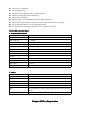
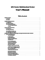
GPS Tracker Multi-functional Tracker
User
User’’s Manual
Table of contents
Chapter I Preface
Preface................................................................................................................................................. 2
I. General
General...................................................................................................................................................... 2
II. Notices
Notices...................................................................................................................................................... 3
Chapter II About the Device
Device............................................................................................................................... 3
I. Components
Components...............................................................................................................................................3
II. Product Features
Features..................................................................................................................................... 3
III. Product Specifications
Specifications........................................................................................................................... 4
1. Technical Specifications
Specifications................................................................................................................... 4
2. Others
Others................................................................................................................................................ 4
Chapter III Use Preparation
Preparation............................................................................................................................... 4
I. Accessories
Accessories.................................................................................................................................................4
II. Charge the Battery
Battery..................................................................................................................................5
III. Installation of SIM Card
Card....................................................................................................................... 5
IV. LED Display Description
Description....................................................................................................................... 6
Chapter IV Commands Corresponding to and Operation Method of Basic Functions
Functions.................................6
1. Mode Switching Function
Function............................................................................................................................6
1. Location Inquiry
Inquiry...............................................................................................................................7
(1) SMS Inquiry
Inquiry....................................................................................................................................7
(2) Platform Inquiry
Inquiry.............................................................................................................................8
2. Setup of Center Number
Number.................................................................................................................. 8
3.SOS Function
Function..................................................................................................................................... 8
( 1) Set Alarming Mode
Mode........................................................................................................................ 9
( 2) Set Pre-saved Number
Number................................................................................................................... 9
4. Monitoring Function
Function........................................................................................................................ 9
5. Set Server Address
Address............................................................................................................................9
6. Regular Upload Interval Setup
Setup..................................................................................................... 10
7. Function of Changing Password
Password................................................................................................... 10
8. Low-Voltage Alarming Function
Function...................................................................................................10
9. Set APN Command
Command.........................................................................................................................10
10. Electronic Fence Function
Function........................................................................................................... 11
(1)GPS Fence Function
Function...................................................................................................................... 11
(2)GSM Fence Function
Function..................................................................................................................... 11
(3) Fence Reading Function
Function...............................................................................................................12
(4) Function of Canceling Fence
Fence........................................................................................................12
11. Auxiliary Functions:
Functions:..................................................................................................................... 12
Notices:
Notices:................................................................................................................................................................ 12
Chapter I Preface
I. General
GPS Tracker represents the perfect combination of GSM and GPS technologies. This
model, with precise dimensions, compact appearance and top workmanship, is the typical design combing
communication products and tracker device.
This model expresses the advanced workmanships in the fields of GSM and GPS. As a professional
security and positioning company, we will provide you with more and better products and services.
Before use, please spend several minutes reading this user’s manual in order to understand operation
details and obtain better services.
II. Notices
1.
2.
3.
Please read carefully this user’s manual and always use correct operation methods to prevent any
possible errors.
The defaulted password of this product is 0000.
This user’s manual is for reference only. If some contents and operation steps are inconsistent with
those for the actual product, the latter will prevail.
Chapter II About the Device
GPS Tracker, as a personal remote positioning device made up of GPS module and
GSM/GPRS module, is compact in dimensions and has high accuracy. On the basis of GPS satellites and under
dynamic conditions, it can provide you with accurate and correct location information. It can transmit the
longitude and latitude coordinates to the authorized mobile phone. With such features, it can be used to protect
and look for our old people and children. Moreover, you can use it for safety purpose and other purposes, such
as remote positioning to protect property safety and follow animals.
I. Components
1. Inbuilt GPS Module
II. Product Features
●
●
●
●
●
●
●
GPS individual or fleet positioning;
Universal in the world;
GSM /GPRS modem supports four frequency bands, i.e. 850/900/1800/1900MHz
High-sensitivity, new workmanship and the most advanced GPS chip;
Can accurately position even if with weak signals;
Can work effectively in limited space such as the remote and narrow places in a city;
Compact size, smaller than business card, easy to hide
●
●
●
●
●
●
●
●
●
Low energy consumption;
Fast signal capturing;
Supports single positioning and continuous tracking;
Supports alarming and remote monitoring;
Supports fast dial button;
Supports the location information inquiry by SMS and Internet
May monitor without disturbing the tracked person and realizes real-time tracking;
Can position the holder by call or mobile phone SMS;
In emergency, press the SOS button to have an accurate positioning.
III. Product Specifications
1. Technical Specifications
GSM module
GSM850/900/1800/1900MHz
GPS chip
Latest JRC
GPS sensitivity
-159dBm
GPS center frequency
L1, 1575.42MHz
GPS positioning accuracy
2-8m
GSM positioning accuracy
50-500m
Speed accuracy
0.1 m/s
Time accuracy
Synchronous with GPS
Default data
WGS-84
Hot start
1s
Warm start
38s
Max. altitude
18000m
Max. speed
515m/s
Gravitational acceleration
﹤4g
2. Others
Working temperature
-20---65℃
Humidity
5%---95%
Dimensions
86mmx38mmx18mm
Voltage
Rechargeable 1100mAh battery (3.7V)
Power supply
DC5V
Standby time
>200h
LED
2 LED lamps to indicate GPS, GSM working state and other
states.
Buttons
One SOS emergency button for emergency aid;
Chapter III Use Preparation
I. Accessories
1. Main unit
2. USB data cable
3. Charger
4. Battery
5.User manual
II. Charge the Battery
Before the use of the tracker, please charge the battery at least 4h via the USB charging cable. For the first
charge, in order to bring the performance of the battery into full play, charge it above 12h.
Indicator of charging:
Red, being charged;
III. Installation of SIM Card
Open the back cover, then you will see the place where the SIM card is placed. Then push the SIM card into
the slot until it comes into its proper position completely and make sure it is locked. See the following figures:
Choose SIM card:
� You may use the GSM card.
� Prepare one SIM card ,make sure it have opened the CALLER ID and send-receive sms function
� Make sure the SIM card has sufficient amount in order to pay the communication cost.
IV. LED Display Description
Blue light indicates GSM working state:
State
Meaning
0.2s on and o.2s off (fast flicker)
0.2s on, 3s off (intermittently flicker)
In call conversation and call coming in
GSM/GPRS normal, but disconnected with server (in server
connection mode)
Normally off
Normal connection with server (in server connection mode)
Normally off
Normal work mode (point-to-point mode)
Red light indicates GPS working state
State
Meaning
0.2s on and 10s off
GPS work normal, have get the real-time valid location
0.2s on and o.2s off (fast flicker)
GPS work normal, trying to get the valid location.
Chapter IV Commands Corresponding to and Operation Method of Basic Functions
Please note that the factory password of this product is the defaulted password 0000.
1. Mode Switching Function
(1) Product Mode Description
Totally, this product has five modes #70X# password ( 0000)##, including respectively:
700 Mode
Mode: When X is 0, the module is working the point-to-point mode of SMS and the result the module
executes and operates will be sent to the user number requesting operation.
Command: #700#0000##
701 Mode
Mode: When the module is working in the SMS center mode, the result the module executes and operates
will be sent to the center number preset by the module.
Command: #701#0000##
703 Mode: The GPRS center mode in which the module is working #704#0000##
Command: #703#0000##
704 Mode: The GPRS center mode in which the module is working. The difference from Mode 3 is that,
when the change distance of one array of data is less than 10m, data will be uploaded as per 1/10 ratio set in
regular time.
Command: #704#0000##
705 Mode: The GPRS center mode in which the module is working. It is required that data should be sent to
the preset IP address by the module in a simple manner and in GPRS mode
Command: #705#0000##
(2) Setup Mode
The user may send and change mode commands with any mobile phone as per his/her own demand. After
the command is set successfully, the mobile phone sending the command will receive the config OK response
message or PASSWORD ERROR in case of wrong password.
1. Location Inquiry
(1) SMS Inquiry
Create 666 + password command via mobile phone and send it to the terminal number; after successful
sending, the guardian’s mobile phone will receive a piece of word message. See the flow as follows:
By the same means, send the command 987 + password to the terminal, then the terminal will return one
piece of website message. The guardian may inquire the location information of the ward attached with local
map through this website message.
In the same way, send the 666 + password command to the terminal; after successful sending, the terminal
will return the detailed GPS data information.
(2) Platform Inquiry
Step 1: Log onto the platform;
Step 2: Click the terminal of the ward, then the map will display the location of the ward.
2. Setup of Center Number
Set the center number by means of SMS or Femoo tools. After the setup is successful, then the mobile
phone will receive the config OK response message returned from the terminal.
Command format: #710#138xxxxxxxx#0000##
3.SOS Function
( 1) Set Alarming Mode
Through SMS or Femoo tools, set the monitoring number to the terminal. After the setup is successful, the
mobile phone sending the SMS will receive the config OK response message from the terminal.
Format: # command code(720)# Alarming mode 0-3# User password, 4 bits # #
Alarm mode 0: No alarm;
Alarm mode 1: Alarm by dialing;
Alarm mode 2: Alarm by SMS. (If the setup mode belongs to 703, 704 or 705, the alarming message will
be sent to the SMS center and the GPRS center).
Alarm mode 3: Alarm by dialing and alarm by SMS. (If the setup mode belongs to 703, 704 or 705, the
alarming message will be sent to the SMS center and the GPRS center
Remarks: The defaulted alarming mode is no alarm.
For example: #720#3#0000##. After this command is executed, the module is set as dialing plus SMS. If
the module executes the function of dialing the first preset number while sending alarming message, after the
setup is successful, the module will send the CONFIG OK response message to the setting mobile phone or the
PASSWORD ER response message in case of wrong password.
( 2) Set Pre-saved Number
Through SMS or Femoo tools, set the monitoring number to the terminal. After the setup is successful, the
mobile phone sending the SMS will receive the config OK response message from the terminal.
Setup format: #711# Phone 1# phone 2# phone 3#0000##
For example:
Note: After the alarming mode and pre-saved number are set successfully, press the SOS button on the
terminal to achieve the alarming function. If no alarming mode is set, the terminal will default as no alarming.
4. Monitoring Function
The pre-saved number may dial the mobile phone numbers stored in the terminal. 30s after dialing, the
terminal will automatically monitor the ward, achieving the monitoring function.
5. Set Server Address
Format: #803# fixed IP address # Port number # password, 4 bits ##
After this command is executed, the APN of the module will be set as per the requirements of the user. The
defaulted setup fixed IP of the APN is 310.85.89.132,; the port number is 3345. In addition, the IP address
may support the direct input of website. After the module sets a new IP, it will cut off the current conduction.
After the setup is successful, the module will return the message CONFIG OK to the setting mobile phone
or the message PASSWORD ER in case of wrong password.
For example: #803#111.211.31.217#20009#0000##
Or set via domain: e.g. #803#www.goldwireless.net#20009#0000##
6. Regular Upload Interval Setup
Format: # command code (730)# time interval (0-99999)# number of return arrays (0-99999)# password, 4
bits ##
The interval between arrays as 0 indicates that the function of returning in regular time is cancelled and
such interval is in second. However, in consideration of the processing time restriction, the minimum
interval is limited to be 5s. This timing function is applicable for various working modes, but in SMS mode,
no matter how many arrays, only one array of message will be returned. After the setup is successful, the
module will return the message CONFIG OK to the setting mobile phone or the message PASSWORD ER
in case of wrong password.
For example:
In SMS mode:
#730#30#1#0000##. After this command is executed, the timing function of the module is activated,
sampling data once and returning one array of message every 30min.
In GPRS mode:
#730#6#10#0000##. After this command is executed, the timing function of the module is activated,
sampling data once and save them every 6s. When the 10 data are sampled, they will be packed and
returned at a time. (The above setup is one upload every minute and 10 arrays of data once).
7. Function of Changing Password
Send the SMS “#770# User new password # User old password ##” by mobile phone to the terminal
number, after successful sending, the mobile phone with such setup will receive one piece of config ok
response information, as shown in the following figure:
8. Low-Voltage Alarming Function
If the terminal of the ward has a very low power and needs to be powered off, the terminal of the ward will
automatically upload one piece of low-voltage alarming command to the monitoring center number.
9. Set APN Command
Create the SMS “802#APN letters or digits, 4-20 bits # Log user name letters or digits 4-20 bits in #
” and send it to the terminal; after
Log password letter or digits 4-20 bits in # terminal password 4 bits ##
##”
executing this command, the terminal will automatically restart and connect to GPRS with the APN set.
Example 1: #802#cmnet###0000##
Example 2:2: #802#GOLD#WIRELESS#888888#0000##
After this command is executed, APN will be GOLD; the login user name is WIRELESS and login
password is 888888。
Note: The default APN of this product is CMNET.
10
10.. Electronic Fence Function
(1)GPS Fence Function
The guardian may log into the system, click the custom deviation setup in the user system manager, enter
the deviation setup interface, choose the longitude and latitude of the center point to be set as fence. Click the
mouse in the Google map, then reading page will display the electronic fence with longitude and latitude set.
See the figure below:
Set fence format: # command number (751) # fence radius # sampling interval # longitude # latitude #
user password ##.
For example: #751#500#5#23.5442N#114.91E#0000##
After the setup is successful, the setting mobile phone will receive a piece of config ok command. Then,
when the ward leaves this area, the terminal will send the alarming information of being out of the fence to the
center number.
(2)GSM Fence Function
The ward may send # command number (740) user password 4 digits ## command to set the GSM
fence. After the setup is successful, the terminal will return the message of CONFIG OK to the setting
mobile phone, or the message of PASSWORD ER if the password is wrong.
For example: #740#0000##
Description of GSM fence: The terminal reads the GSM base station information, including that the main
base station and the adjacent base stations. Take the first four digits and keep them in the module. If the
base station has many data with different first digits, they all must be saved. And initiate the protection
status. In the state of protection, the module will read the data of all base stations (1-7) once every 5
minutes, and take the first 4 digits to compare with the protection data. If all the first 4 digits of the data of
all base station are consistent with the existing data, then dial or send alarming messages to the user
according to the alarming setup.
For example: #740#0000##. After the fence is set, the terminal will alarm in the case where it is moved
about 3-5km out of the fence.
(3) Fence Reading Function
Send commands to the terminal: # command number (752) # user password 4 digits ##; after the
command is set successfully, the terminal will read the data of the module fence working status and return
message to the sending mobile phone, or PASSWORD ER if the password is wrong.
For example: #752#0000##
Return: #open:1#lat:11456.209400#lng:2233.470100#distance:500#time:5#status:2
Where, open: 1 indicates fence open; Open: 0 indicates fence closed;
lat:11456.209400, latitude;
lng: 2233.470100; longitude;
distance: 500; fence radius;
time: 5 sampling interval;
status: 2 , terminal has obtained valid satellite data, fence works normally;
status: 1; fence open, but there are no valid satellite data have been received;
status: 0, no electronic fence is set.
(4) Function of Canceling Fence
Command name: # command number (760) # user password 4-digits ##
Example: #760#0000##
After the terminal receiving this command, all fence settings will be cancelled.
Advice; Do not set GSM fence and GPS fence at the same time.
11. Auxiliary Functions:
(1)#901## Command of reading user parameters;
(2)#902## Command of reading GPRS parameters
(3)#903## Restart command
(4)#904## GPRS connection command
(5)#905## GPRS disconnection command
Notices:
1. This device is of non-waterproof design.
2. This device must work with the cooperation of GSM/GPRS network.
3. Make sure that the SIM card has sufficient balance in order to avoid inconvenience in
use.
4. This device will not be able to work in case of power-off and out of the service area,
even if you are a registered user.
5. This device supports the dual positioning mode of GPS and GSM/GPRS.
6. Please use this device in a legal area, any illegal consequence will be borne by the user.