1
K2000 Digital Temperature Controller
Installation & Operators Guide
Rev E - July 2014
This document outlines the installation and setup of the MMR K2000 Digital Temperature Controller.
Page |1
CONTENTS
About the K2000 Digital Temperature Controller
Specifications
System Requirements
Environmental and Safety
3
3
3
Hardware Installation
Installation
Front / Real Panel Interface
Changing port numbers in Windows
Getting Started
Using the 4-Wire Kelvin Board for Auxiliary Temp Monitoring
4
5
6
7
9
General Operation
Setting a Temperature
Main Software Suite Interface and Spooler
Custom Ramp Programming
Programmable User Ports
Dual Temp Live Monitor
Graphing Functions
Zooming
Heat Capacity Experiment
Communications Protocol
10
14
15
16
18
20
21
22
24
Troubleshooting
Troubleshooting
26
Additional Information
Help Desk and MMR Contact Information
Declaration of Conformity
27
28
Page |2
About the K2000 Digital Temperature Controller
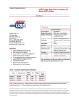
Specifications
The K2000 Temperature controller is built on and intended to replace the proven K20 Temperature Controller
previously offered by MMR Technologies. This temperature controller through self tuning PID offers stable
temperature measurement and control to 0.05K (Result may vary with load and vacuum). Manual temperature
control and monitoring is also possible through the built in User Interface. These devices are intended for use with
MMR Refrigerators only.
Voltage:
Power Consumption:
Temperature Inputs:
Sensor Type:
Resolution:
PID Control:
Heater Power:
Temperature Range:
Communications:
Weight:
Dimensions:
Environmental:
115VAC 60Hz / 220VAC 50Hz (Not user selectable, Refer to label at rear of unit)
60W
2
PT100 RTD F Series (4-wire Kelvin connection)
±0.0.5K
Yes (1 Channel)
0 - 10W
60K - 1000K
RS232 or USB1.0 (See communications protocol)
10Lbs
8.5"(W) x 3.5"(H) x 14.25"(D)
Indoor use only, 5C - 40C Temperature, 2000M Max Altitude, 80% Humidity for
temperatures up to 31 °C decreasing linearly to 50 % Rel humidity at 40 °C.
System Requirements
For computer control the K2000 Temperature controller is designed for use with 'MMR Technologies Suite' which
must be installed prior to using this device. For custom control of this device see page 24, please note MMR may
not support custom configurations and in some cases the warranty may be void.
Operating System:
Hardware:
Memory RAM:
Memory Hard Disk:
Peripheral Interface:
Mac OS, Linux:
Windows 2000, Windows XP, Windows 7, Windows 8
32BIT / 64BIT INTEL or AMD Processor
2GB
1GB
1x RS232 Serial or USB1.0.
Not Supported
Environmental and Safety
The K2000 Digital Temperature controller is built on and intended to replace the proven K20 Temperature
Controller previously offered by MMR Technologies. Please observe the following safety warnings. Do not open
the enclosure, do not operate on any voltage other than specified, do not attempt to service or modify the
equipment, do not operate in wet/damp locations. Warning, electrical shock, injury or death may occur if the
device is opened or the earth modified. Use only the cables supplied with the device and ensure a proper Ground
is present. The SB1000 should only be used as intended and should not be used for any other purpose. Any nonintended use could cause fire, loss of life, loss of equipment, and bodily harm. User assumes all risk should the
equipment be misused, modified, or use in an unintended manner. Contact MMR for service
Page |3
Hardware Installation
Installation
Before proceeding please ensure the MMR Technologies Software Suite is installed and the following items are
present:
•
•
•
•
•
•
•
1x K2000 Temperature Controller (Correct Voltage)
1x AC Power Cable
1x RS232 DB9 Serial Cable
1x USB 3FT Cable
1x User Manual and Software / Driver Installation CD
1x 4FT Refrigerator Ribbon Cable
1x MMR 4-Wire Kelvin Connection Breakout Board
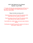
Please connect the K2000 Temperature Controller as shown below. Do not connect both the RS232 Serial cable
and USB cable together, these are provided as two options should you be short of spare PC ports.
Once connected and with the PC running you may now power-up the K2000 Temperature Controller. Please first
insure the AC Power switch at the rear of the unit is 'ON' (see figure 6 for further information). Press the front
button labeled power to power up the unit. If the USB cable was used Windows will automatically assign a
comport. This must be identified, and if necessary changed to be in the range of 1-16. (See page 5 or contact your
system administrator) Please note down the assigned Comm port Number as this will be required to communicate
with the device.
Page |4
Hardware Installation
Changing Port Numbers in Windows
(Note: Administrator access maybe needed, contact your IT department)
1/. Open Device Manager.
(Control Panel -> Device Manager)
2/. Select the corresponding Serial Converter
Device.
(Right Click -> Left Click Properties)
3/. Click on the 'Port Settings' Tab.
4/. Click Advanced.
5/. Select a Comm port between 1 - 16 that is
not in-use by other hardware. Click OK.
(Note: On some computers you may need to
disconnect (unplug) and reconnect the device
to make the changes permanent.)
Page |5
Hardware Installation
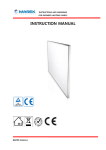
Front / Rear Panel Interface
Note: The Power button must be held for 3 seconds to power down the unit.
*Replace fuse with 3.15A Slow Blow (IEC 127-2 or similar) ONLY.
Page |6
Hardware Installation
Getting Started
Before Starting the MMR Technologies Suite software it will be necessary to familiarize yourself with the Built In
User Interface, there are several modes which are outlined below. These can be navigated by using the "Mode"
button.
Mode 1: COMPUTER CONTROL (This mode must be selected for Communicating with the software)
Ready State
No Refrigerator Present
Ramping to 345.00K
Holding at 345.00K
Mode 2: MANUAL CONTROL (This mode is for standalone Temperature Control, No PC)
Select a Temperature and
Press Start/Stop
Select a Ramp Rate and
Press Start/Stop
Press Start/Stop to Begin
Ramp Target Reached
Press' Start / Stop' to Pause or
and Resume. Press 'Mode'
to Exit.
Ramp in Progress
Page |7
Hardware Installation
Getting Started
Mode 3: LIVE MONITOR (This mode simultaneously displays the Temperature from BOTH Refrigerator Inputs)
The controller will automatically switch to this mode when the PC Software is plotting both Temperatures.
No further computer control is possible in this mode.
Mode 4: USER OUTPUTS (This mode is for the manual toggling of the Dry Relay contacts at the rear of the unit)
(See page 16, for information on the Rear User Ports.
Pressing the adjacent 'Arrow Keys' will toggle the Outputs, the selected state of the Outputs will be restored each
time the controller is powered up.
These Dry Contact Outputs are electrically Isolated from the Unit (including grounding). The user can pass any signal
through these relay outputs for external control of temperature related hardware or ALARM circuitry. Autonomous
control of these Ports is possible through the MMR Software Suite.
Approvals
UL E29244, CSA LR81479
Contact ratings
500mA, 20VDC
Mechanical endurance 100x106 operations
Contact Data
Rated voltage :20VDC, 500mA
Max. switching voltage : 100VDC
Rated current : 500mA, 20VDC
Limiting making current 500mA
Limiting breaking current 500mA
Contact material: Ruthenium
Initial contact resistance 200mΩ max. at 10mA, 6VDC
Operate/release time max., incl. bounce: 1.5/0.5ms
Insulation Data
Initial dielectric strength between open contacts: 250VDC,
between contact and coil: 500VDC
Initial insulation resistance between insulated elements: 1010Ω at
100VDC
Capacitance between open contacts typ. 0.5pF
Page |8
Hardware Installation
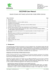
Using the 4-Wire Kelvin Board
The purpose of this board is to allow easy user integration of an additional sensor (TYPE PT100 RTD - F Series) to
the system for auxiliary temperature monitoring purposes. Although this card can interface to either refrigerator
port it is generally intended for use on Refrigerator Port #2. One unique feature of the K2000 is that refrigerators
can be hot swapped while the device is powered ON. See below for wiring information.
The advantage of using a 4-wire Kelvin connection is the conductors (cable) used can by of varying length and
immune to various forms of interference. PT100 (100ohm Platinum Resistors) are readily available from suppliers
such as OMEGA (Part# F2020-100-B-100), and also from MMR Technologies (Part# 3192369-003).
The Datasheet for the recommended sensor is http://www.omega.com/pptst/F1500_F2000_F4000.html
Page |9
General Operation
Setting a Temperature
With the Hardware now installed and an MMR Refrigerator properly attached (see documentation supplied with
Refrigerator) it is now time to start the MMR Software Suite.
Locate and run the 'MMR Technologies Suite' icon on the Desktop or Start Menu.
Step 1 - Device ports are easily verified through the welcome screen above, select the port number the K2000
Temperature Controller is connected to (shown as present next to the K2000) and press 'Poll'. If the K2000 is
connected to that port, powered on and set to 'Computer Control' it will respond with a Device name and Version
number.
If the port number is not visible try refreshing the port list by clicking the refresh icon above the "Poll'' buttons. If
this does not resolve the issue try restarting the computer. For further assistance contact your system administrator
and finally the MMR Helpdesk (See contact information on Page 27)
Step 2- Select 'Refrigerator Temperature Ramp' This will select the 'Temperature & Power vs Time' plot.
This experiment allows the user to set any given temperature in the range of 70K - 700K depending on attached
refrigerator and Gas system. Please see the manual that accompanied your refrigerator for Low and High
temperature limits. Refrigerators can be easily destroyed if these limits aren't adhered to.
Step3 - Press 'Begin'
P a g e | 10
General Operation
Setting a Temperature
Before proceeding, Graphing and Plotting parameters can be modified.
Graph Name, Comments;
An Experiment name and further comments can be also be added to the project. These will be included when
printing a Plot later.
Y-Min / Y-Max
These parameters can be manually set, however through a built in easy-to-use Zoom function it may not be
required. These settings cannot be modified in 'Dual Temp Live Monitor' mode.
Plot Frequency
This option is used for extended recording times >24 Hrs. The Graphing software is capable of processing 2Million
points. And will record continuously once started, however points will be lost from the beginning of the plot when
the recorded points reach 2 Million. (Ever point over 2 million recorded, 1 point will be deleted from the
beginning of the recording.?)
Startup / Shutdown Auto Standby
This option is recommended at all times when cooling. Should the temperature control be terminated at any
point in the experiment the Set Point (K2000 Temperature Setting) will automatically be set at 300K (Or Room
Temperature) This will prevent run away heating/cooling leading to refrigerator damage.
Press 'OK' to Start.
P a g e | 11
General Operation
Setting a Temperature
The above illustration outlines the buttons and their associated functions of the Temperature Graph, to begin
logging select 'Start Logging', the current Set Point is already set at 300K as previously the 'Startup / Shutdown
Auto Standby' option was selected.
The Front LCD display or User Interface of the K2000 Temperature controller should also show 300.00K as the
Setpoint, this indicated the device is communicating correctly with the software.
To proceed to a specific temperature select "New Temp". Note: At any time during an experiment clicking "Temp
Off" will disable the K2000 Temperature Control and allow the Refrigerator to freely cool or warm to 300K.
P a g e | 12
General Operation
Setting a Temperature
The above window allows the user to input a given temperature to one decimal place. (e.g 310.1)
If no decimal place is necessary simply enter 310. A ramp rate between 1K / Min and 15 / Min is also
essential to ensure no damage to the refrigerator is done. This ramp rate is applicable to heating and
cooling ramps. (positive or negative slope).
In some rare situations it may be necessary to skip the Ramp Control in which case the option "Skip Ramp
Control" can be selected. It is worth noting that this is dangerous and can potentially destroy the
refrigerator.
The X Axis Scale (Time) automatically increments as the plot proceeds, the Power Scale can be selected
from the master 'K2000' menu shown on page 14.
P a g e | 13
General Operation
Main Interface
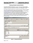
The main interface of the MMR Technologies Suite is shown above, this is the primary container for all
MMR applications. The Applicable items for the K2000 Temperature Controller are show above.
Double Clicking of the Refrigerator Temperature (bottom right) will display customization options which
include "Color" and "Temperature Unit". This is further explained in the Software Installation Guide.
K2000 Spooler
[Main Suite -> K2000 - > Show Spooler]
This window shows the communications queue and response from the associated device, in this case
the K2000 Temperature Controller. Troubleshooting is the primary use for this window. However
clicking "Send" is a short cut to the' Main Communications Console' outlined in the software Installation
Guide.
P a g e | 14
General Operation
Custom Ramp Programming
[Main Suite -> K2000 -> Custom Ramp]
This is a feature unique to the K2000 Temperature Controller in which multiple temperatures and ramp
rates can be preset and allowed to run autonomously.
Destination Temp:
Hold Time:
Ramp Rate:
On Completion:
Stop Logging:
The required set point. (Temperature Setting, Set Point)
Otherwise known as 'Wait' or 'Soak Time' this is the amount of time in seconds
the controller waits once the destination temp has been reached before
proceeding to the next temperature setting.
The Slope of the Heating or Cooling.
Options 'Control Off' or 'Hold'.
Control Off disables the temperature control. It is worth ensuring the Auto
Standby option is selected (see page 11) if cooling is active.
Hold holds the refrigerator at the last temperature. If you are unsure if 'Auto
Standby' is selected it is worth adding 300K and Hold as the last step in the
ramp.
Terminates the plot after the Ramp completion.
P a g e | 15
General Operation
User Port Programming
[Main Suite -> K2000 -> User Outputs]
The built in Dry Contact Relays inside the K2000 Temperature Controller (see page 8) can be easily
controlled either manually or automatically.
Manual Control
Toggling of the Ports is achieved using the 'User Output''
Control shown to the left.
Note: The K2000 must be set to 'Computer Control'
Automatic Control (To set a User Port program Click 'Program' in the "User Outputs" Window)
The above application allows up to two separate programs to be run simultaneously. There are two
program types (Thermostat and Alarm).
PORT - The user output the program will control (1 or 2)
STATE - Relay State Below the Setpoint if Heating and Above the Setpoint if Cooling
PROGRAM TYPE - Thermostat (Real Time Temperature Control), Alarm Latch (A state change if the
Setpoint is breached, this requires user acknowledgement should it occur.)
CONTROL TYPE - This tells the controller if the Experiment Control is Heating or Cooling. (See Page 17)
SENSOR - Which Refrigerator Temperature to Monitor (1 or 2)
SETPOINT - The Control Temperature
HYSTERESIS - The temperature control Gap between the state change and Setpoint. The larger the
hysteresis setting the less state changes occur when the temperature is close / equal
to the Setpoint.
State Change (Heating) = Setpoint - Hysteresis
State Change (Cooling) = Setpoint + Hysteresis
SHOW SETPOINT - Shows the Setpoint setting on the Temperature Plot.
P a g e | 16
General Operation
User Port Programming
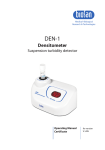
HYSTERESIS and EXPERIMENT TYPE
The illustration to the left outlines
the behavior of the Experiment Type
vs Hysteresis,
A = Relay state changed.
B = Relay restored to original state.
(note when the 'Program Type' is
'Alarm' there is no hysteresis setting
as the Alarm latches at one point
only)
ALARM
The Alarm message will appear when the Setpoint condition is reached
or exceeded, after acknowledging the message after 5 seconds it will reappear unless the Alarm condition is resolved or the program is
cancelled.
PROGRAM RUNNING
When a program is set the above message is displayed below the
temperature in the Main Software Suite.
NOTES
The software updates the user port status to the controller every 5 seconds. This means that some
precision control may be difficult because of this delay.
P a g e | 17
General Operation
Dual Temp Live Monitor
[Main Suite -> Suite Main -> New Project] or [Close Entire Application and Restart]
This Project allows both temperatures to be plotted Simultaneously , NO temperature control is
available in this mode as it is strictly intended for monitoring purposes only. When selecting this project
the software instructs the K2000 Temperature Controller to switch to 'Live Monitor' Mode.
When starting a new "Dual Temp Live Monitor" project it is possible to name the individual
Temperature inputs. The (Y) Scale cannot be changed in this mode.
P a g e | 18
General Operation
Dual Temp Live Monitor
Both Temperatures are displayed simultaneously along with their associated labels. To change color or
Temperature Units double click the Temperatures. The following control will be shown.
To change the temperature unit for a given Temperature
input, select amongst K,C or F. Note the unit change does not
affect the plot or stored data. This is for display purposes only.
To select a color double click on the desired color selection
and press OK to set.
P a g e | 19
General Operation
Graphing Functions
Double clicking the graph plot displays the Customization window, many options are available for
customization the appearance of the graph and plot along with changing the plot type or hiding
altogether. (Fig 1)
Additionally Right Clicking on the graph plot area shows a quick menu (Fig 2 )
Figure 1.
Figure 2.
Note: These settings are not permanent and will be reset each time a New Graph project is started
Example of changing the Power (W) Plot to a Bar Graph.
P a g e | 20
General Operation
Graphing Functions
The above buttons are associated with ever graph plot and have the following functions.
EXPORT - Opens the Export Window, this allows exporting the graph to the clipboard, to an image and
raw data (including .txt or .csv)
PRINT - Prints the graph in image form. Axis Info, Title and Comments are included.
FULLSCREEN - Displays a snapshot of the graph in Full screen, press 'ESC' to close. Note: The graph does
not update in Full screen mode.
MARK - Add Annotations to graph, this allows the user to permanently add comments to a specific
location on the graph plot. These comments are saved and included in printing.
COMMENTS - Modify Project Comments
UNDO ZOOM - Restores the graph to its original scale and view.
Zooming
To zoom click and drag a box to select a desired view. To undo zoom press 'z' or click "UNDO ZOOM"
P a g e | 21
General Operation
Heat Capacity Experiment
The Heat Capacity Experiment is a new feature offered by MMR Technologies and is unique to the
K2000 Temperature Controller. The objective of this experiment is to measure thermal mass and/or
detect phase transitions in a given sample. The experiment consists of measuring the precise power
required to Heat an unloaded refrigerator from T1 to T2 and then repeating the process with a sample
loaded on the refrigerator. The ΔP is then calculated for each measurement point and a Difference curve
plotted. Similar Vacuums and proper mounting of the sample is required for accuracy.
Although the experiment is autonomous the user must specify 4 Main parameters.
Start Temperature - T1 The Desired Start Temperature (70 - 700K).
Soak Time - The hold time, to allow for minimal thermal difference between sample and sensor.
Final Temperature - T2 The final Temperature (must be greater than the start Temperature).
Ramp Rate - Desired Ramp Rate or Slope.
The upper plot shows the complete experiment data, the lower plot shows the unwanted data removed.
P a g e | 22
General Operation
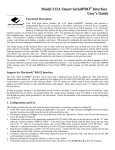
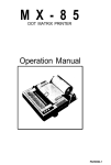
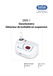
Heat Capacity Experiment Results
The above plots show the overlaid Power Curves from the Unloaded Run and the Loaded Run.
The Difference plot is the DELTA P of the two curves which is related to the thermal mass of the sample.
P a g e | 23
General Operation
Communications Protocol
Main Communications Type:
Communications Interfaces:
Serial Settings:
Handshaking:
Echo:
Bus Pairing:
Hardware CTS Timeout:
Data Format:
Serial
RS232, USB1.0
9600,N,8,1
Hardware RTS/CTS
Yes
Parallel
1000ms
ASCII / Plain Text
System Commands
Command
"T"
"S"
"U"
"C"
"O"
"M"
"N"
"R"
"D"
Format
TX
SXXXX
UXX
CXX
O1
M1
N1
R1
D1
Example
T1 = Temp 1 / T2 = Temp 2
S3005 = 300.5K / S775 = 77.5K
U11 = User Port 1 ON / U10 = User Port1 OFF
C1 to C10
Description
Get Temp
Set Temp
Set User Port
Set PID Constant
Power Down
Get Constant
Get Device Name
Restart
Live Monitor Mode
Note: Sending command S0 disables PID temperature control
Communications & Byte Order
Command Example: 'S3123' (Set temp to 312.3K)
1/. Set RTS High
2/. Wait for CTS
3/. Send 'S' as a Character (VB Example on Next Page)
4/. Send Temperature as a 2-Byte Word (Highbyte First, Lowbyte Second)
5/. Set RTS Low
Warning: Sending Temperature commands directly to the Controller bypass's the Ramp Control
protection, permanent damage to the MMR Refrigerator is likely.
P a g e | 24
General Operation
Communications Protocol
Visual Basic Example - Sending a set temperature command
Private Sub Form_Load()
MSComm1.CommPort = 2
MSComm1.DTREnable = False
MSComm1.Settings = "9600,N,8,1"
MSComm1.RTSEnable = False
MSComm1.OutBufferSize = 1024
MSComm1.RThreshold = 1
MSComm1.SThreshold = 0
MSComm1.PortOpen = True
End Sub
Function SetTemperature()
Dim command As Long
Dim temp As Integer
Dim counter As String
temp = 3123
'Set Temperature to 312.3K
counter = 0
MSComm1.RTSEnable = True
'Set RTS High
While MSComm1.CTSHolding <> True
counter = counter + 1
'Wait for CTS Signal
If counter > 200000 Then
MSComm1.RTSEnable = False
'Reset RTS
MsgBox ("Time Out")
Exit Function
End If
Wend
MSComm1.OutBufferCount = 0
MSComm1.InBufferCount = 0
'Clear Buffers
MSComm1.Output = Chr$(S) + Chr$(temp / 256) + Chr$(temp Mod 256) + Chr$(13)
MSComm1.RTSEnable = False
End Function
P a g e | 25
Troubleshooting
Troubleshooting
Symptom Solution
Cannot Communicate with K2000 Ensure Unit is properly connected and powered
on. Press Reset, Check that the device is connected
to the correct Communications Port and the
drivers are successfully loaded.
No Temperature is displayed Please check Refrigerator Cables, Check that the
temperature is displaying on the K2000 LCD User
Interface Screen.
No Lights on K2000 Ensure Unit is plugged into an AC Power source,
the rear power switch is on. Check Fuse.
Temperature Ramp is Unstable Check refrigerator is under vacuum.
Adjust PID Constant to 10.
Refrigerator doesn't Cool or Heat Refer to Refrigerator Operators Manual, check for
damage to refrigerator.
Temperature Accuracy has degraded Return Refrigerator to MMR for Sensor service.
Software has an Error message Contact MMR helpdesk
For all other errors or issues please contact the MMR Help Desk (See Page 27)
P a g e | 26
Troubleshooting
Help Desk and MMR Contact Information
Help Desk Email Address:
[email protected]
Bug Reporting:
[email protected]
Technical Support Email Address:
[email protected]
Sales & Marketing Department:
[email protected]
Help Desk:
Office Hours:
Physical Address:
+1 650 962 9620
7:30am - 5:00pm (Pacific Time)
Monday - Friday
1400 North Shoreline Blvd, Suite A5
Mountain View, California 94043
USA
P a g e | 27
Declaration of Conformity
Declaration of Conformity
Manufacturer:
Model Name:
Date:
Expires:
MMR Technologies
K2000
July 2014
July 2018
UL / IEC 61010
Application of Council Directives:
Low Voltage Directive (LVD) 2006/95/EC
Standards to which Conformity is Declared: IEC EN 61010-1 3rd Edition
Electrical equipment for measurement, control, and laboratory use
Pressure Equipment Directive (97/23/EC)
Conformity is declared to Annex I Essential Requirements of the Directive
Application of Council Directives:
Electromagnetic Compatibility Directive (EMC) 2004/108/EC
Conformity is declared to Annex I and II (EMC) 2004/108/EC
P a g e | 28