1
Part No. IA005001
Feb. 2013
USER’S MANUAL
INSULATION RESISTANCE TESTER
TOS7200
DANGER
This Tester generates high voltage!
Any incorrect handling may cause death.
Read Chapter 2 “PRECAUTIONS ON HANDLING”
in this manual to prevent accident.
Keep this manual near the tester for easy access
of the operator.
About the TOS7200 Manuals
There are four TOS7200 Manuals listed as follows.
Setup Guide (PDF)
This manual is intended for first-time users of this product. It provides an overview of
the product and notes on usage. It also explains how to set up the product for testing
the DUT. Always read this manual before using the product.
Quick Reference
This manual explains Panel description and operation briefly.
Safety Information
This document contains general safety precautions for this product. Keep them in
mind and make sure to observe them.
User’s Manual (this manual)
This manual is intended for first-time users of this product. It provides an overview of
the product and notes on usage. It also explains how to configure the product, operate
the product, remotely controlling the product, perform maintenance on the product,
and so on.
TOS7200 Manuals are intended for users of the Insulation Resistance Tester and their
instructors. Explanations are given under the presumption that the reader has knowledge about the electrical aspects of electrical safety testing.
Every effort has been made to ensure the accuracy of this manual. However, if you
have any questions, or find any errors or omissions, please contact your Kikusui agent
or distributor.
If you find any misplaced or missing pages in this manual, it will be replaced. If the
manual gets lost or soiled, a new copy can be provided for a fee. In either case, please
contact your Kikusui agent or distributor, and provide the “Kikusui Part No.” given
on the cover.
After you have finished reading manuals, store them so that you can use it for reference at any time.
The company names and product names that appear in this manual are the trademarks
or registered trademarks of the respective manufacturers.
Reproduction and reprinting of this operation manual, whole or partially, without our
permission is prohibited.
Both unit specifications and manual contents are subject to change without notice.
© 2001-2013 Copyright Kikusui Electronics Corporation.
To supervisor in charge of operation
• If the operator does not read the language used in this manual,
translate the manual into appropriate language.
• Help the operator in understanding this manual before operation.
• Keep this manual near the Tester for easy access of the operator.
For your own safety (to avoid electrification)
While the Tester is delivering its test voltage, never touch the following areas, or else, you will be electrified, and run the risk of
death by electric shock.
• the output terminal
• the test leadwires connected to the output terminal
• the Device Under Test (DUT)
• any part of the Tester, which is electrically connected to the output terminal, and
• the same part as above immediately after the output has been
cut off when in the DC mode of test.
TOS7200
I
Safety Symbols
For the safe use and safe maintenance of this product, the
following symbols are used throughout this manual and on
the product. Understand the meanings of the symbols and
observe the instructions they indicate (the choice of symbols
used depends on the products).
OR
DANGER
WARNING
CAUTION
Indicates that a high voltage (over 1000 V) is used here.
Touching the part causes a possibly fatal electric shock.
If physical contact is required by your work, start work
only after you make sure that no voltage is output here.
Indicates an imminently hazardous situation which, if
ignored, will result in death or serious injury.
Indicates a potentially hazardous situation which, if
ignored, could result in death or serious injury.
Indicates a potentially hazardous situation which, if
ignored, may result in damage to the product and other
property.
Shows that the act indicated is prohibited.
Is placed before the sign “DANGER, ” “ WARNING,” or
“CAUTION” to emphasize these. When this symbol is
marked on the product, see the relevant sections in this
manual.
Indicates a protective conductor terminal.
Indicates a chassis(frame) terminal.
II Safety Symbols
TOS7200
Safety Precautions
The following safety precautions must be observed to avoid
fire hazard, electrical shock, accidents, and other failures.
Keep them in mind and make sure that all of them are
observed properly.
ration
Ope
al
Manu
Users
• This product must be used only by qualified personnel who understand the contents of this operation manual.
• If it is handled by disqualified personnel, personal
injury may result. Be sure to handle it under
supervision of qualified personnel (those who
have electrical knowledge.)
• This product is not designed or produced for
home-use or use by general consumers.
Purposes of use
• Do not use the product for purposes other than
those described in the operation manual.
Line
Voltage
Input power
• Use the product with the specified input power
voltage.
• For applying power, use the AC power cord provided. Note that the provided power cord is not
use with some products that can switch among
different input power voltages or use 100 V and
200 V without switching between them. In such a
case, use an appropriate power cord.
Fuse
• With products with a fuse holder on the exterior
surface, the fuse can be replaced with a new one.
When replacing a fuse, use the one which has
appropriate shape, ratings, and specifications.
TOS7200
Safety Precautions III
Cover
• There are parts inside the product which may
cause physical hazards. Do not remove the external cover.
Installation
• When installing products be sure to observe "Precautions for Installation" described in this manual.
• To avoid electrical shock, connect the protective
ground terminal to electrical ground (safety
ground).
• When installing products with casters, be sure to
lock the casters.
Relocation
• Turn off the power switch and then disconnect all
cables when relocating the product.
• Use two or more persons when relocating the
product which weights more than 20 kg. The
weight of the products can be found on the rear
panel of the product and/or in this operation manual.
• Use extra precautions such as using more people
when relocating into or out of present locations
including inclines or steps. Also handle carefully
when relocating tall products as they can fall over
easily.
• Be sure the operation manual be included when
the product is relocated.
IV Safety Precautions
TOS7200
Operation
ck?
Che
• Check that the AC input voltage setting and the
fuse rating are satisfied and that there is no abnormality on the surface of the AC power cord. Be sure
to unplug the AC power cord.
• If any abnormality or failure is detected in the products, stop using it immediately. Unplug the AC
power cord. Be careful not to allow the product to
be used before it is completely repaired.
• Do not disassemble or modify the product. If it must
be modified, contact Kikusui distributor/agent.
Maintenance and checking
• To avoid electrical shock, be absolutely sure to
unplug the AC power cord or stop applying power
before performing maintenance or checking.
• Do not remove the cover when performing maintenance or checking.
• To maintain performance and safe operation of
the product, it is recommended that periodic
maintenance, checking, cleaning, and calibration
be performed.
Service
• Internal service is to be done by Kikusui service
engineers. If the product must be adjusted or
repaired, contact Kikusui distributor/agent.
TOS7200
Safety Precautions V
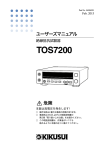
Front panel and Rear panel
• Be sure to read Chapter 2 "Precautions On Handling".
Danger
HIGH VOLTAGE
terminal
Lighted lamp means that the
Tester is in “DANGER
HIGH VOLTAGE” state.
OUTPUT
MEMORY
MEMORY
VOLTAGE
VOLTAGE
Before using the remotecontrol function, read the
Operation Manual.
RESISTANCE
RESISTANCE
TIMER
TIMER
To change testing conditions,
press the STOP button.
To ensure safety, be sure to
connect to an earth ground.
See “1.5 Grounding”
Danger
HIGH VOLTAGE
terminal
Before using the remotecontrol function, read the
Operation Manual.
VI Safety Precautions
TOS7200
Contents
Safety Symbols- - - - - - - - - - - - - - - - - - - - - - - - - - - - - - - - - - - - - II
Safety Precautions - - - - - - - - - - - - - - - - - - - - - - - - - - - - - - - - - - III
Preface
About This Manual - - - - - - - - - - - - - - - - - - - - - - - - - - - - - - - - - - - - P-1
Outline of the TOS7200 - - - - - - - - - - - - - - - - - - - - - - - - - - - - - - - - - P-1
Features - - - - - - - - - - - - - - - - - - - - - - - - - - - - - - - - - - - - - - - - - - - - P-2
Option - - - - - - - - - - - - - - - - - - - - - - - - - - - - - - - - - - - - - - - - - - - - - P-3
Chapter1 Setup
1.1
1.2
1.3
1.4
1.5
Unpacking - - - - - - - - - - - - - - - - - - - - - - - - - - - - - - - - - - - - - - - Precautions for installation - - - - - - - - - - - - - - - - - - - - - - - - - - - - Precautions for Moving- - - - - - - - - - - - - - - - - - - - - - - - - - - - - - - Connecting the AC Power cord - - - - - - - - - - - - - - - - - - - - - - - - - Grounding- - - - - - - - - - - - - - - - - - - - - - - - - - - - - - - - - - - - - - - - -
1-1
1-2
1-4
1-5
1-6
Chapter2 Precautions On Handling
2.1
2.2
2.3
2.4
2.5
2.6
Prohibited Operations - - - - - - - - - - - - - - - - - - - - - - - - - - - - - - - - Action When in Emergency - - - - - - - - - - - - - - - - - - - - - - - - - - - - Precautions on Testing - - - - - - - - - - - - - - - - - - - - - - - - - - - - - - - Warning for Residual High Voltages - - - - - - - - - - - - - - - - - - - - - - Dangerous States of Failed Tester - - - - - - - - - - - - - - - - - - - - - - - - Daily Checking - - - - - - - - - - - - - - - - - - - - - - - - - - - - - - - - - - - - -
2-1
2-2
2-2
2-4
2-5
2-5
Chapter3 Basic Operation
3.1
3.2
Turning ON the Power - - - - - - - - - - - - - - - - - - - - - - - - - - - - - - - - 3-1
Setting the Test Conditions - - - - - - - - - - - - - - - - - - - - - - - - - - - - - 3-3
3.2.1 Setting the Test Voltage- - - - - - - - - - - - - - - - - - - - - - - - - - - - 3-4
3.2.2 Setting the Lower Judgment - - - - - - - - - - - - - - - - - - - - - - - - - 3-5
3.2.3 Setting a Lower Resistance (LOWER) - - - - - - - - - - - - - - - - - - 3-6
3.2.4 Setting the Upper Judgment - - - - - - - - - - - - - - - - - - - - - - - - - 3-8
3.2.5 Setting the Upper Resistance (UPPER) - - - - - - - - - - - - - - - - - 3-8
3.2.6 Setting the Timer Function- - - - - - - - - - - - - - - - - - - - - - - - - - 3-9
3.2.7 Setting the Test Time (TEST TIME) - - - - - - - - - - - - - - - - - - 3-10
3.2.8 Setting the Wait Time (WAIT TIME) - - - - - - - - - - - - - - - - - 3-10
3.3 Connecting the Test leadwires - - - - - - - - - - - - - - - - - - - - - - - - - - 3-12
3.3.1 Connecting to the Tester - - - - - - - - - - - - - - - - - - - - - - - - - - 3-12
3.3.2 Connecting to the DUT - - - - - - - - - - - - - - - - - - - - - - - - - - - 3-12
3.4 Starting and Ending a Test- - - - - - - - - - - - - - - - - - - - - - - - - - - - - 3-16
TOS7200
Contents VII
3.5
3.6
3.7
3.8
3.9
3.4.1 Starting the Test - - - - - - - - - - - - - - - - - - - - - - - - - - - - - - - - 3-16
3.4.2 Ending the Test - - - - - - - - - - - - - - - - - - - - - - - - - - - - - - - - - 3-17
System Settings - - - - - - - - - - - - - - - - - - - - - - - - - - - - - - - - - - - - 3-20
Panel Memory - - - - - - - - - - - - - - - - - - - - - - - - - - - - - - - - - - - - - 3-25
3.6.1 Storing in Panel Memory - - - - - - - - - - - - - - - - - - - - - - - - - - 3-25
3.6.2 Recalling a Panel Memory - - - - - - - - - - - - - - - - - - - - - - - - - 3-25
Key Lock- - - - - - - - - - - - - - - - - - - - - - - - - - - - - - - - - - - - - - - - - 3-26
Invalid Settings- - - - - - - - - - - - - - - - - - - - - - - - - - - - - - - - - - - - - 3-26
Initialize - - - - - - - - - - - - - - - - - - - - - - - - - - - - - - - - - - - - - - - - - 3-27
Chapter4 Using Terminals and Connectors
4.1
4.2
REMOTE Terminal- - - - - - - - - - - - - - - - - - - - - - - - - - - - - - - - - - -4-2
SIGNAL I/O Connector - - - - - - - - - - - - - - - - - - - - - - - - - - - - - - - -4-4
4.2.1 Specifications for the SIGNAL I/O Connector - - - - - - - - - - - - -4-5
4.2.2 Example of Use- - - - - - - - - - - - - - - - - - - - - - - - - - - - - - - - - -4-8
4.2.3 Starting a Test- - - - - - - - - - - - - - - - - - - - - - - - - - - - - - - - - - 4-10
4.2.4 Recalling the Panel Memory - - - - - - - - - - - - - - - - - - - - - - - - 4-12
4.3 ANALOG OUT Connector- - - - - - - - - - - - - - - - - - - - - - - - - - - - - 4-13
Chapter5 RS-232C Control
5.1
5.2
Preparation - - - - - - - - - - - - - - - - - - - - - - - - - - - - - - - - - - - - - - - -5-2
Messages and Terminator- - - - - - - - - - - - - - - - - - - - - - - - - - - - - - -5-5
5.2.1 Messages - - - - - - - - - - - - - - - - - - - - - - - - - - - - - - - - - - - - - -5-5
5.2.2 Terminator - - - - - - - - - - - - - - - - - - - - - - - - - - - - - - - - - - - - -5-7
5.3 Device Messages - - - - - - - - - - - - - - - - - - - - - - - - - - - - - - - - - - - -5-7
5.3.1 Register-Related and General Purpose Messages - - - - - - - - - - -5-8
5.3.2 Test-Related Messages - - - - - - - - - - - - - - - - - - - - - - - - - - - - 5-14
5.3.3 System-Related Messages- - - - - - - - - - - - - - - - - - - - - - - - - - 5-21
5.3.4 Memory-Related Messages - - - - - - - - - - - - - - - - - - - - - - - - - 5-25
5.4 Registers - - - - - - - - - - - - - - - - - - - - - - - - - - - - - - - - - - - - - - - - - 5-28
5.5 List of Device Messages - - - - - - - - - - - - - - - - - - - - - - - - - - - - - - 5-33
Chapter6 Part Names and Functions
6.1
6.2
Front Panel - - - - - - - - - - - - - - - - - - - - - - - - - - - - - - - - - - - - - - - -6-1
Rear Panel - - - - - - - - - - - - - - - - - - - - - - - - - - - - - - - - - - - - - - - - -6-8
Chapter7 Maintenance
7.1
7.2
7.3
7.4
7.5
Cleaning - - - - - - - - - - - - - - - - - - - - - - - - - - - - - - - - - - - - - - - - - -7-1
Inspection - - - - - - - - - - - - - - - - - - - - - - - - - - - - - - - - - - - - - - - - -7-1
Maintenance - - - - - - - - - - - - - - - - - - - - - - - - - - - - - - - - - - - - - - -7-2
Calibration- - - - - - - - - - - - - - - - - - - - - - - - - - - - - - - - - - - - - - - - -7-2
Troubleshooting - - - - - - - - - - - - - - - - - - - - - - - - - - - - - - - - - - - - -7-2
VIII Contents
TOS7200
Chapter8 Specifications
Basic performance- - - - - - - - - - - - - - - - - - - - - - - - - - - - - - - - - - - - Interface and Other Functions - - - - - - - - - - - - - - - - - - - - - - - - - - - - General Specifications - - - - - - - - - - - - - - - - - - - - - - - - - - - - - - - - - Dimensions - - - - - - - - - - - - - - - - - - - - - - - - - - - - - - - - - - - - - - - - -
8-1
8-4
8-7
8-8
Appendix
Sample programs- - - - - - - - - - - - - - - - - - - - - - - - - - - - - - - - - - - - - - A-1
Index - - - - - - - - - - - - - - - - - - - - - - - - - - - - - - - - - - - - - - - - - - - - - I-1
TOS7200
Contents IX
X Contents
TOS7200
Preface
About This Manual
This Operation Manual is for the TOS7200 insulation resistance tester.
This Manual applies to products incorporating ROM of version “1.0x.”
The ROM version will be displayed on the voltmeter immediately
after power-on.
Outline of the TOS7200
The TOS7200 is an insulation resistance tester that is available in a
wide range of electric and electronic components and equipment, and
allows any test voltage to be set. Because it features the window comparator and timer function, the tester is capable of efficiently conducting insulation resistance tests based on various safety standards.
Moreover, with the panel memory, which can be recalled externally
and the RS-232C interface provided as standard equipment, the tester
can flexibly handle automated systems.
TOS7200
Preface P-1
Features
■ Arbitrary setting of the output voltage
The output voltage may be set to between 25 V and 1 000 V. Thus,
insulation resistance tests can be conducted on a wide range of electric
and electronic components and equipment.
Table P-1
Test voltage Resistance measurement range
25 V
0.03 M
to
250 M
50 V
0.05 M
to
500 M
100 V
0.10 M
to
1 000 M
125 V
0.13 M
to
1 250 M
250 V
0.25 M
to
2 500 M
500 V
0.50 M
to
5 000 M
1 000 V
1.00 M
to
5 000 M
■ Equipped with a discharge function
The tester features a discharge function, which discharges the electric
charge in the device being tested. This allows tests to be conducted
more safely.
■ Equipped with a window comparator
The tester has adopted a window comparator system capable of making judgments on both the upper and lower limits. This prevents noncontact-caused judgment errors and other errors.
■ Equipped with a timer function
The tester features a timer function that allows the test time to be set.
It also enables setting of the wait time, allowing more secure measurements and evaluation.
■ Rear output terminals
Output terminals on the rear panel improve wiring workability in an
automated production line or other workshops.
■ Analog output
The rear panel is provided with an analog output section for measured
resistance values.
P-2 Preface
TOS7200
■ Equipped with a panel memory
As the TOS7200 can store up to 10 types of panel settings, settings
complying with various standards can easily be invoked to conduct
tests.
■ Provided with a SIGNAL I/O connector and remote-control
terminal
Equipped with a SIGNAL I/O connector as standard equipment, to
output the test status as an external I/O and handle starting/stopping
of tests and recalling of panel memory. In addition, the front panel
has a remote-control terminal that allows tests to be started/stopped
remotely.
■ Incorporating the RS-232C interface as standard equipment
The tester features an RS-232C interface as standard equipment for
easy connection to a PC, allowing measured data to be obtained.
Option
This Tester features the following options:
■ RC01-TOS/RC02-TOS remote-control boxes
These remote-control boxes remotely control starting/stopping of the
tester when connected to the REMOTE terminal on the front panel.
The RC01-TOS has one START switch, while the RC02-TOS has
two.
For the RC02-TOS, a test starts only when both switches are pressed
simultaneously.
TOS7200
Preface P-3
Functions
• OPERATE switch
The TEST switch can be operated only when this switch is set to
ON. When it is turned OFF, a test in progress will be stopped forcibly.
• START switch
When the OPERATE switch is ON and the tester is in ready status, pressing this switch starts testing.
• STOP switch
This switch is used to shut off the output voltage or cancel a FAIL
judgment. It serves the same function as the STOP switch on the
front panel of the tester.
RC01-TOS: 200 mm (W) x 70 mm(H) x 39 mm (D)
RC02-TOS: 330 mm (W) x 70 mm (H) x 39 mm (D)
NOTE
P-4 Preface
• Connection of a remote-control box to the tester requires the
use of a DIN-Mini DIN adaptor. For DIN-Mini DIN adaptors,
contact your Kikusui distributor/agent.
DD-5P/6P DIN-mini DIN adaptor.
[84250]
TOS7200
Chapter 1
Setup
This chapter describes the procedures from unpacking to installation
to operation checking.
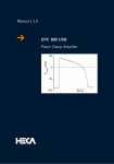
1.1
Unpacking
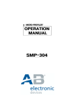
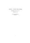
Upon receiving the product, confirm that the necessary accessories
are included and have not been damaged in transit. Fig. 1-1 shows a
list of the accessories.
Should any damage or shortage be found, please contact Kikusui distributor/agent.
or
or
Rated voltage: 125 Vac
PLUG: NEMA5-15
[85-AA-0003]
Rated voltage: 250 Vac
PLUG: CEE7/7
[85-10-0840]
Rated voltage: 250 Vac
PLUG: GB1002
[85-10-0790]
Power cord (1 pc.)
The power cord that is provided varies depending on
the destination for the product at the factory-shipment.
High-voltage test
lead (1 set)
[TL08-TOS]
Setup Guide
(1 pc.)
[Z1-005-700]
Safety Information
(1 pc.)
[Z1-005-040]
Fig.1-1
NOTE
TOS7200
Quick Reference
Japanese: 1 pc. [Z1-005-710]
English: 1 pc. [Z1-005-712]
CD-ROM (1 pc.)
[SA-5158]
Accessories
• Retain the packing material for future transport.
Setup 1-1
1.2
Precautions for installation
Directions for installation locations
Be sure to observe the following precautions when installing the tester.
■ Do not use the tester in a flammable atmosphere.
To prevent explosion or fire, do not use the tester near alcohol, thinner, or other combustible materials, or in an atmosphere containing
such vapors.
■ Avoid locations where the tester is exposed to high temperatures or direct sunlight.
Do not locate the tester near a heater or in areas subject to drastic
temperature changes.
Operating temperature range:+5 °C to +35 °C (+41 °F to +95 °F)
Storage temperature range: -20 °C to +70 °C (-4 °F to +158 °F)
■ Avoid humid environments.
Do not locate the tester in a high-humidity environment—near a
boiler, humidifier, or water supply.
Operating humidity range: 20 % to 80 % RH
(no dew condensation permitted)
Storage humidity range:
90 % RH or less
(no dew condensation permitted)
Condensation may occur even within the operating humidity range. In
that case, do not start using the tester until the location is completely
dry.
■ Do not place the tester in a corrosive atmosphere.
Do not install the tester in a corrosive atmosphere or one containing
sulfuric acid mist or the like. This may cause corrosion of various
conductors and imperfect contact with connectors, leading to malfunction and failure, or in the worst case, a fire.
■ Do not locate the tester in a dusty environment.
Dirt and dust in the tester may cause electrical shock or fire.
■ Do not use the tester where ventilation is poor.
Prepare sufficient space around the tester to allow for air flow.
1-2 Setup
TOS7200
■ Do not place the tester on a tilted surface or in a location
subject to vibrations.
If placed on a non-level surface or in a location subject to vibration,
the tester may fall, resulting in damage and injury.
■ Do not use the tester in locations affected by strong magnetic or electric fields.
Operation in a location subject to magnetic or electric fields may
cause the tester to malfunction, resulting in electrical shock or fire.
■ Do not use the tester in locations near a sensitive measuring instrument or receiver.
Operation in a location subject, may cause such equipment may be
affected by noise generated by the tester.
■ Secure adequate space around the power plug.
Do not insert the power plug to an outlet where accessibility to the
plug is poor. And, do not place objects near the outlet that would
result in poor accessibility to the plug.
■ Use the product in an industrial environment.
This product may cause interference if used in residential areas. Such
use must be avoided unless the user takes special measures to reduce
electromagnetic emissions to prevent interference to the reception of
radio and television broadcasts
TOS7200
Setup 1-3
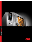
Use of the legs
These legs are used to raise the front part of the tester so that the
screen on the front panel is easier to see and the keys are easier to
operate.
To use the legs, pull them toward the front until you hear a click.
Fig.1-2
Raising the Legs
CAUTION • When the legs are raised and used, do not place any
article on the tester or exert force on it.
1.3
Precautions for Moving
When moving or transporting the tester to an installation site, observe
the following precautions.
■ When moving the tester, Disconnect all wires from it.
Moving the tester without disconnecting the cables may result in
breakage of the wire or injury due to the tester tipping over.
■ Retract the legs.
Moving the tester with the legs raised may result in breakage of the
legs.
■ For transportation, use the special packing material for the
tester.
Transport the tester in its original package to prevent vibration and
falls, which may damage the tester. If you require packing material,
contact Kikusui distributor/agent.
1-4 Setup
TOS7200
1.4
Connecting the AC Power cord
The power cord that is provided varies depending on the destination
for the product at the factory-shipment.
WARNING • The tester is designed to operate from the overvoltage category II. Do not operate it from the overvoltage category III or IV.
• The AC power cord for 100 V system has a rated
voltage of 125 VAC. If this AC power cord is used at
the line voltage of a 200 V system, replace the AC
power cord with that satisfying that line voltage.
An appropriate AC power cord must be selected by
qualified personnel. If it is difficult to obtain the AC
power cord, consult your Kikusui distributor/agent.
• Do not use the AC power cord provided with the product as a AC
power cord for other instruments.
[85-AA-0003]
PLUG:NEMA5-15
[85-AA-0005]
PLUG:CEE7/7
[85-10-0790]
PLUG:GB1002
Fig.1-3
TOS7200
Power cord for 100 V system
Rated voltage: 125 VAC
Rated current: 10 A
Power cord for 200 V system
Rated voltage: 250 VAC
Rated current: 10 A
AC power cord
Setup 1-5
Connection procedure
1. Check that the supply voltage is within the line voltage
range of the tester.
Allowable voltage range: 85 V to 250 VAC
Frequency range: 47 Hz to 63 Hz
2. Turn OFF the POWER switch.
3. Connect the AC power cord to the AC LINE connector on
the rear panel.
Use the provided power code or power code that is selected by
qualified personnel.
4. Plug in the AC power cord.
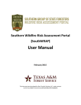
1.5
Grounding
WARNING • Be sure to connect the tester to an electrical ground
(safety ground).
• This tester is designed as a Class I equipment
(equipment protected against electric shock with protective grounding in addition to basic insulation).
Therefore, electric shock may occur without proper
grounding.
To ensure safety, be sure to ground the tester.
Connect the AC power cord to a
three-contact grounded electrical
outlet.
Grounded three-contact
electrical outlet
1-6 Setup
TOS7200
Chapter 2 Precautions On Handling
This chapter describes the precautions to be followed in the handling
of this tester.
When using the tester, take utmost care to ensure safety.
WARNING • The tester derivers a 1 000 V DC test voltage which
can cause human injury or death. When operating
the tester, be extremely careful and observe the cautions, warnings, and other instructions given in this
chapter.
2.1
Prohibited Operations
■ Do not turn on/off the power repeatedly
After turning OFF the power switch, be sure to allow several seconds
or more before turning it ON again. Do not repeat turning ON/OFF
the power switch rapidly –if you do this, the protectors of the Tester
may not be able to render their protective functions properly.
Do not turn OFF the power switch when the tester is delivering its test
voltage–you may do this only in case of emergency.
TOS7200
Precautions On Handling 2-1
2.2
Action When in Emergency
In case of an emergency (such as electric shock hazard or burning of
DUT), take the following actions. You may do either (a) or (b) first.
But be sure to do both.
(a) Turn OFF the power switch of the Tester.
(b) Disconnect the AC power cord of the Tester from the
AC line receptacle.
2.3
Precautions on Testing
■ Precautions for Pausing Tests
When changing test conditions, press the STOP switch once to take
precautions.
If you are not going to resume the test soon or if you are leaving the
Test area, be sure to turn-OFF the POWER switch.
OUTPUT
MEMORY
MEMORY
VOLTAGE
VOLTAGE
RESISTANCE
RESISTANCE
TIMER
TIMER
STOP
switch
POWER
switch
Fig.2-1
Suspending testing and operation
2-2 Precautions On Handling
TOS7200
■ Items Charged Up to Dangerous High Voltages
When in test, the DUT, test leadwires, HIGH terminal, and LOW terminal can be charged up to dangerous high voltages. Never touch
them when in test.
WARNING • If the HIGH terminal is short-circuited to ground, high
voltage is applied to the LOW terminal, making it dangerous to touch. During testing, do not touch the DUT,
test leadwires, HIGH terminal, or LOW terminal.
• The vinyl sheaths of the alligator clips of the test
leadwires which are supplied accompanying the Tester have no sufficient insulation for the high test voltages. Never touch them when in test.
Alligator clip
Never touch this part.
Fig.2-2
Supplied Test leadwires
■ Matters to be Sure of After Turning-OFF Power
If you have to touch the DUT, test leadwires, HIGH terminal, and/or
LOW terminal for re-connections or other reasons, be sure of the following matter.
The DANGER lamp has gone out.
■ Warnings for Remote Control
Be extremely careful when operating the Tester in the remote control
mode in which the dangerous high test voltage is ON/OFF-controlled
remotely. Provide protective means as follows:
• Provide means to assure that the test setup does not
become the test voltage is being delivered by inadvertent operation.
• Provide means to assure that none can touch the DUT,
test leadwires, HIGH terminal, and LOW terminal when
the test voltage is being delivered.
TOS7200
Precautions On Handling 2-3
2.4
Warning for Residual High Voltages
WARNING • In insulation resistance testing, the test leadwire, and
DUT are charged to a high voltage. The tester is
equipped with a discharge circuit, but some time is
nonetheless required to discharge them after the output is cut off. There is a danger of electric shock during discharge. To avoid electric shock, take the
utmost care to ensure that the DUT, test leadwire,
and highly charged parts around the output terminal
are not touched. If it is necessary to touch them, be
sure to confirm the following:
The DANGER lamp has gone out.
• As soon as the output is cut off, the tester’s discharge
circuit starts forced discharging (discharge function).
Do not disconnect the DUT during a test or prior to
completion of discharging.
Discharge time
The length of the discharge time varies according to the properties of
the DUT and the test voltage.
Discharge is conducted at a resistance of approximately 25 k in
insulation resistance testing.
When no DUT is connected, the tester itself requires this following
lengths of time to reduce the internal capacitor voltage to 30 V.
• Insulation resistance testing at 1 000 V: Approximately 0.5 ms
Assuming that a 0.05 µF capacitor is tested, the following lengths of
time are required to reduce the charge to 30 V.
V is as follows:
• Insulation resistance testing at 1 000 V: Approximately 5 ms
If the DUT is disconnected during a test or before the completion of
discharging, assuming that the DUT has a capacity of 0.01 µF and a
parallel resistance of 100 M, approximately 3.5 seconds at 1 000 V
is required for the DUT to discharge to 30 V.
When the approximate time constant of the DUT is known, the time
required for discharging to 30 V after the output is cut off is calculated as the time constant times the value given above.
2-4 Precautions On Handling
TOS7200
2.5
Dangerous States of Failed Tester
Typical possible dangerous states of the Tester are as shown below
and in which cases the most dangerous situation that “the high test
voltage remains delivered and won't be turned off!” may occur.
When this situation has occurred, immediately turn OFF the power
switch and disconnect the AC power cable from the AC line receptacle.
• The DANGER lamp does not go out despite you have
pressed the STOP switch.
Also when the Tester is in other malfunctioning states than the above,
there is a possibility that the output voltage is delivered irrespective of
your proper operating procedure. Never use the Tester when it has
failed.
WARNING • Keep the Tester away of other people until you call
our service engineer for help.
• Immediately call your Kikusui distributor/agent. It is
hazardous for an unqualified person to attempt to
troubleshoot any Tester problem.
2.6
Daily Checking
To avoid accidents, confirm at least the following before starting
operation:
• The tester is connected to an earth ground.
• The coating of the test leadwires are free from cracks, fissures, and
breakage.
• The test leadwires are not broken.
• When a test is started without the test leadwires connected to each
other in the UPPER OFF condition, a FAIL judgment must not be
made.
• When a test is started with the test leadwires short-circuited in a
LOWER ON condition, a FAIL judgment must be made.
TOS7200
Precautions On Handling 2-5
2-6 Precautions On Handling
TOS7200
Chapter 3
Basic Operation
This chapter describes the basic operations performed from the front
panel, such as setting of the test conditions and system settings.
3.1
Turning ON the Power
WARNING • Before turning ON the power, always confirm that the
AC power is within the allowable line-voltage range
indicated on the rear panel of the tester. For more
information, see “1.4 Connecting the AC Power cord”.
• To prevent electric shock, be sure to turn OFF the
POWER switch before disconnecting the cable for
the SIGNAL I/O or RS-232C connector.
• When the power is turned on, the tester lights up all
LEDs on the front panel to perform self-testing.
To ensure safety, be sure to confirm that each LED is
lit before operating the tester. In particular, conducting a test without checking whether the DANGER
lamp is broken is very dangerous. The DANGER
lamp lights up during the self-testing, but this does
not indicate that the output voltage is being generated.
CAUTION • After turning OFF the POWER switch, wait a few seconds, and then turn it on again. Turning the POWER
switch on and off repetitively within a short period
may damage the tester.
TOS7200
Basic Operation 3-1
Power-on procedure
1. Confirm that the AC power is within the allowable line voltage range indicated on the rear panel of the tester.
2. Confirm that the AC power cord is properly connected to the
AC LINE connector on the rear panel of the tester.
3. Connect the other plug of the AC power cord to an electrical
outlet.
4. Turn ON the POWER switch of the tester.
This causes the on-board ROM version number to appear on the
voltmeter and “7200”, representing the model of the tester, to
appear on the resistance meter.
Following these displays, the voltmeter and resistance meter
change to the displays status when the POWER switch was last
turned off.
ROM version
Fig.3-1
3-2 Basic Operation
Model
Example of Display of the Version Number
TOS7200
3.2
Setting the Test Conditions
NOTE
• If a setting is invalid, the tester cannot start a test. For invalid
settings, see “3.8 Invalid Settings”.
• A setting is not accepted in the KEYLOCK status (KEYLOCK LED lit), during a test, or during output of a PASS/
FAIL judgment result.
The test conditions include the following items:
• Test voltage
• Lower resistance (LOWER) and ON/OFF of the lower judgment
• Upper resistance (UPPER) and ON/OFF of the upper judgment
• Test duration (TEST TIME) and ON/OFF of the timer function
• Wait time (WAIT TIME)
TOS7200
Basic Operation 3-3
3.2.1 Setting the Test Voltage
The tester enables setting of the test voltage to be applied to the DUT
in the range of -10 V to -1 020 V DC (resolution: 1 V). (Note that the
minus sign “-” is not indicated.)
Voltmeter
MEMORY
MEMORY
VOLTAGE
VOLTAGE
VOLT key
Fig.3-2
RESISTANCE
RESISTANCE
TIMER
TIMER
For moving the cursor or
changing a numerical value
Setting the Test Voltage
1. Press the VOLT key to move the cursor to the voltmeter’s 7segment LED.
This causes the rightmost digit of the LED to blink, indicating that
the cursor is positioned at this digit.
or
key to move the cursor to the digit at
2. Press the
which a value is to be set.
or
key to
3. With the SHIFT key held down, press the
change the value.
If necessary, change the value at another digit to reach the desired
test-voltage value.
NOTE
• When the lower judgment is activated, making settings such
that the value obtained by dividing the test voltage by the
lower resistance exceeds 1.1 mA causes the LOWER LED to
blink, notifying the operator that a test cannot be conducted.
In such cases, lower the test voltage or raise the lower resistance.
3-4 Basic Operation
TOS7200
3.2.2 Setting the Lower Judgment
When the lower judgment is set to ON, if the insulation resistance
value falls below the lower resistance set in “3.2.3 Setting a Lower
Resistance (LOWER)”, the tester makes a FAIL judgment and ends
the test.
Setting the lower judgment to OFF causes the tester not to return a
FAIL judgment, even if the insulation resistance falls below the lower
resistance.
ON/OFF of the lower judgment is set after the tester is placed in system mode. For the system mode, see “3.5 System Settings”.
1. With the SHIFT key held down, press the VOLT key to enter
the system mode.
This causes the leftmost digit of the voltmeter (digit indicated as
DOUBLE ACTION) to blink, indicating that the cursor is positioned at this digit.
2. Press the or key to move the cursor to the LOWER ON
position.
or
key to
3. With the SHIFT key held down, press the
change the setting.
The display indicates that “0” is OFF and “1” is ON.
4. Press the STOP switch to exit the system mode.
CAUTION • If the upper or lower judgment function is OFF, no
FAIL judgment is made. Note that, if this function is
off, PASS judgment is made when the timer is turned
on.
TOS7200
Basic Operation 3-5
3.2.3 Setting a Lower Resistance (LOWER)
The lower resistance can be set in the range of 0.01 M to 5 000 M
(resolution of 0.01 M for the range of 0.01 M to 9.99 M, of 0.1
M for that of 10.0 M to 99.9 M, and of 1 M for that of 100
M to 5 000 M) (provided that the current is within the maximum
rated current).
When the wait time elapses following the start of a test, if an insulation resistance value below the lower resistance is detected, the tester
makes a FAIL judgment and ends the test.
UPPER LED
UPPER ON LED
MEMORY
MEMORY
VOLTAGE
VOLTAGE
Resistance meter
RESISTANCE
RESISTANCE
TIMER
TIMER
UPPER/LOWER key
Fig.3-3
LOWER LED
For moving the cursor or
changing a numerical value
Setting a Lower Resistance
1. Press the UPPER/LOWER key to move the cursor to the 7segment LED of the resistance meter.
This causes the rightmost digit of the LED to blink, indicating that
the cursor is positioned at this digit.
2. Check whether the LOWER LED is lit.
If it is, the lower resistance is displayed. If the UPPER LED is lit,
the value displayed is the upper resistance. In such cases, press the
UPPER/LOWER key again to light up the LOWER LED.
or
key to move the cursor to the digit at
3. Press the
which a value is to be set.
or
key to
4. With the SHIFT key held down, press the
change the value.
If necessary, change the value at another digit to achieve the
desired lower resistance.
3-6 Basic Operation
TOS7200
NOTE
TOS7200
• When both the upper and lower judgments are activated, setting the lower resistance to a value higher than the upper
resistance causes the UPPER LED to blink, notifying the
operator that a test cannot be conducted. (The lower resistance is set to 1.00 M at factory shipment.)
In such cases, lower the lower resistance or raise the upper
resistance.
• When the lower judgment is activated, making settings such
that the value obtained by dividing the test voltage by the
lower resistance exceeds 1.1 mA causes the LOWER LED to
blink, notifying the operator that a test cannot be conducted.
In such a case, lower the test voltage or raise the lower resistance.
• To measure the resistance value despite the fact that it causes
a drop in the test voltage, use a tester with the lower judgment
set to OFF. In such a case, if the output voltage exceeds the
range of ±(2 % of setting + 2 V), the measured voltage value
displayed on the voltmeter blinks, notifying the operator of a
drop in the test voltage.
• A lower judgment cannot be made until the wait time has
elapsed since the start of a test.
Basic Operation 3-7
3.2.4 Setting the Upper Judgment
When the upper judgment is set to ON, if the insulation resistance
value exceeds the upper resistance set in “3.2.5 Setting the Upper
Resistance (UPPER)”, the tester returns a FAIL judgment and ends
the test.
ON and OFF of the upper judgment can be alternately selected by
pressing the UPPER/LOWER (UPPER ON) key with the SHIFT key
held down. When the upper judgment has been activated, the UPPER
ON LED lights up.
CAUTION • If the upper or lower judgment function is OFF, no
FAIL judgment is made. Note that, if this function is
off, PASS judgment is made when the timer is turned
on.
3.2.5 Setting the Upper Resistance (UPPER)
The upper resistance can be set in the range of 0.01 M to 5 000 M
(resolution of 0.01 M for the range of 0.01 M to 9.99 M, of 0.1
M for that of 10.0 M to 99.9 M, and of 1 M for that of 100
M to 5 000 M) (provided that the current is within the maximum
rated current).
UPPER LED
UPPER ON LED
MEMORY
MEMORY
VOLTAGE
VOLTAGE
Resistance meter
RESISTANCE
RESISTANCE
TIMER
TIMER
UPPER/LOWER key
Fig.3-4
LOWER LED
For moving the cursor or
changing a numerical value
Setting the Upper Resistance
1. Press the UPPER/LOWER key to move the cursor to the 7segment LED of the resistance meter.
This causes the rightmost digit of the LED to blink, indicating that
the cursor is positioned at this digit.
3-8 Basic Operation
TOS7200
2. Check whether the UPPER LED is lit.
If it is, the upper resistance is displayed. If the LOWER LED is lit,
the value displayed is the lower resistance. In such a case, press
the UPPER/LOWER key again to light up the UPPER LED.
or
key to move the cursor to the digit at
3. Press the
which a value is to be set.
or
key to
4. With the SHIFT key held down, press the
change the value.
If necessary, change the value at another digit to reach the desired
upper resistance.
NOTE
• When both the upper and lower judgments are activated, setting the upper resistance to a value below the lower resistance
causes the UPPER LED to blink, notifying the operator that
the test cannot be conducted. (The upper resistance is set to
100 M at factory shipment.)
In such cases, raise the upper resistance, lower the lower
resistance, or set the lower judgment to OFF.
• When the fixed range has been selected, setting the upper
judgment to ON causes the UPPER ON LED to blink, notifying the operator that the test cannot be conducted. In such
cases, set the range to auto-range or set the upper judgment to
OFF.
3.2.6 Setting the Timer Function
When the timer function is set to ON, the duration of testing can be
controlled by following the procedure specified in “3.2.7 Setting the
Test Time (TEST TIME)”. When the set test time elapses with the
resistance value within the upper and lower resistances during testing,
the tester makes a PASS judgment and ends the test.
ON and OFF of the timer function can be alternately selected by
pressing the TEST/WAIT (TIMER ON) key with the SHIFT key held
down. When the timer function has been activated, the TIMER ON
LED lights up.
TOS7200
Basic Operation 3-9
3.2.7 Setting the Test Time (TEST TIME)
The test duration during which the set test voltage is applied to the
DUT can be set in the range of 0.5 s to 999 s (resolution of 0.1 s for
the range of 0.5 s to 99.9 s and of 1 s for that of 100 s to 999 s).
1. Press the TEST/WAIT key to move the cursor to the timer’s
7-segment LED.
This causes the rightmost digit of the LED to blink, indicating that
the cursor is positioned at this digit.
2. Check whether the WAIT LED is lit.
If it is not lit, the test time is displayed. If it is lit, the value displayed is the wait time. In such a case, press the TEST/WAIT key
again to turn off the WAIT LED.
or
key to move the cursor to the digit at
3. Press the
which a value is to be set.
or
key to
4. With the SHIFT key held down, press the
change the value.
If necessary, change the value at another digit to reach the desired
test time.
NOTE
• Setting the test time shorter than the wait time with the timer
function set to ON causes the TIMER ON LED to blink, notifying the operator that the test cannot be conducted.
3.2.8 Setting the Wait Time (WAIT TIME)
In insulation resistance testing, application of the test voltage to the
DUT, including a capacitive DUT, results in a lower insulation resistance measurement than expected until completion of charge, due to
the charge current. To eliminate the effects of the charge current during lower judgment, the tester provides a wait time extending from
the application of the test voltage to the start of lower judgment.
The wait time can be set in the range of 0.3 s to 10 s (resolution of 0.1
s).
3-10 Basic Operation
TOS7200
1. Press the TEST/WAIT key to move the cursor to the timer’s
7-segment LED.
This causes the rightmost digit of the LED to blink, indicating that
the cursor is positioned at this digit.
2. Check whether the WAIT LED is lit.
If it is, the wait time is displayed. If the WAIT LED is not lit, the
value displayed is the test time. In such cases, press the TEST/
WAIT key again to make the WAIT LED light.
or
key to move the cursor to the digit at
3. Press the
which a value is to be set.
or
key to
4. With the SHIFT key held down, press the
change the value.
If necessary, change the value of another digit to set the desired
wait time.
WAIT LED
TIMER ON LED
Timer
MEMORY
MEMORY
VOLTAGE
VOLTAGE
RESISTANCE
RESISTANCE
TIMER
TIMER
TEST/WAIT key
Fig.3-5
NOTE
TOS7200
For moving the cursor or
changing a numerical value
Setting the Test Time or Wait Time
• Setting the test time shorter than the wait time with the timer
function set to ON causes the TIMER ON LED to blink, notifying the operator that the test cannot be conducted.
Basic Operation 3-11
3.3
Connecting the Test leadwires
WARNING • Insecure connection of a test leadwire may cause the
entire DUT to be charged to high voltage, posing a
danger. Take care to connect the test leadwires
securely.
3.3.1 Connecting to the Tester
Connecting the low voltage side test leadwire
1.
2.
3.
4.
Press the STOP switch.
Check that the DANGER lamp is off.
Check that there is no breakage in the test leadwires.
Connect the low voltage side test leadwire to the LOW terminal of the tester.
Connecting the high voltage side test leadwire
Perform the following procedure after connecting the low voltage
side test leadwire:
1. Press the STOP switch.
2. Confirm that the DANGER lamp is off.
3. Connect the high voltage side test leadwire to the HIGH terminal of the tester.
4. Short-circuit the low voltage side and high voltage side test
leadwires to confirm that no high voltage is output.
3.3.2 Connecting to the DUT
Connect the test leadwires to the DUT after connecting the low voltage side and high voltage side test leadwires to the tester.
1. Press the STOP switch.
2. Confirm that the DANGER lamp is off.
3. Short-circuit the high voltage side test leadwire using the
low voltage side test leadwire to confirm that no high voltage
is applied.
4. Connect the low voltage side test leadwire to the DUT.
5. Connect the high voltage side test leadwire to the DUT.
3-12 Basic Operation
TOS7200
WARNING • Never touch the HIGH terminal, the LOW terminal, a
test leadwire, or the DUT during a test (or while the
DANGER lamp is lit).
NOTE
• The polarity of the output terminal of the tester is negative.
The HIGH terminal has negative (-) polarity, while the LOW
terminal has positive (+) polarity.
■ Connecting to a grounded DUT
When conducting an insulation resistance test on a DUT with one terminal grounded, connect the LOW terminal of the tester to the
grounding terminal of the DUT.
For example, to conduct an insulation resistance test across the AC
LINE and grounding terminal of the grounded DUT, connect the
LOW terminal of the tester to the grounding terminal of the DUT and
the HIGH terminal of the tester to the AC LINE of the DUT. See Fig.
3-6.
OUTPUT
MEMORY
MEMORY
VOLTAGE
VOLTAGE
RESISTANCE
RESISTANCE
TIMER
TIMER
TOS7200
L
AC LINE
N
Grounded DUT
Fig.3-6
TOS7200
Connecting the Tester to a Grounded DUT
(insulation resistance test across the AC
LINE and chassis of the DUT)
Basic Operation 3-13
NOTE
• Reason that the LOW terminal of the tester is connected
to the grounding terminal of the DUT that has been
grounded:
It is appropriate to connect the line terminal (LINE) to the
negative (-) side of the power source and the grounding terminal (EARTH) to the positive (+) side. When testing the insulation of insulation wires or cables with respect to ground for
direct current, connecting the negative polarity of the power
source to the core and the positive polarity to ground will generally provide smaller measured values than when the reverse
polarities are connected. Thus, the above-noted connection is
considered appropriate for the detection of insulation failures.
• For the above reason, the tester connects the negative polarity
of the power source to the HIGH terminal and the positive
polarity of the power source to the LOW terminal. Thus, for
insulation resistance testing involving a DUT with one
grounded terminal, it is appropriate to connect the LOW terminal of the tester to the grounding terminal of the DUT, and
the HIGH terminal of the tester to the LIVE terminal of the
DUT.
WARNING • Short-circuiting the HIGH terminal of the tester to
ground causes high voltages to be applied to the
LOW terminal, making it dangerous to touch. Do not
touch the DUT, test leadwires, HIGH terminal, or
LOW terminal during a test (or while the DANGER
lamp is lit).
3-14 Basic Operation
TOS7200
■ Connecting to an ungrounded DUT
When conducting insulation resistance testing on a DUT that has not
been grounded, connect the HIGH and LOW terminals of the tester to
any two points of the DUT.
OUTPUT
MEMORY
MEMORY
VOLTAGE
VOLTAGE
RESISTANCE
RESISTANCE
TIMER
TIMER
TOS7200
Ungrounded DUT
Fig.3-7
TOS7200
Connecting the Tester to an Ungrounded
DUT
Basic Operation 3-15
3.4
Starting and Ending a Test
NOTE
• If a setting is invalid, the tester cannot start a test. For invalid
settings, see “3.8 Invalid Settings”.
• When a PASS/FAIL judgment result is being output, the tester
cannot start a test.
• If the STOP switch has been pressed, the tester cannot start a
test. (This includes a stop signal from the remote control.)
• When DOUBLE ACTION is activated, the test can be started
by pressing the STOP switch, then pressing the START
switch within approximately a half-second. Otherwise, the
test cannot be started. For more information on DOUBLE
ACTION, see “3.5 System Settings”.
• When MOMENTARY is activated, the tester performs the test
only while the START switch is being held down. For more
information on MOMENTARY, see “3.5 System Settings”.
3.4.1 Starting the Test
• To start the test, press the START switch.
• When the test starts, the DANGER lamp lights up, the voltmeter
and resistance meter indicate the measured values, and the timer
indicates the time.
• The time indicated after the start of the test differs depending on
whether the timer function is set to ON or OFF.
When the timer is ON: The time remaining of the set time is indicated.
When the timer is OFF: The elapsed test duration is indicated.
(Note that if the test time exceeds 999 seconds, “999” blinks.)
• The WAIT LED blinks during the wait time.
DANGER lamp lit
Fig.3-8
3-16 Basic Operation
Measured resistance value
Example of Display during a Test
TOS7200
3.4.2 Ending the Test
PASS judgment
Measured resistance value
PASS lamp lit
Fig.3-9
Example of Display for PASS Judgment
When the timer is ON:
• When the test time elapses without a FAIL judgment during testing,
the tester makes a PASS judgment and ends the test.
• When a PASS judgment is made, the PASS lamp lights up and the
buzzer sounds. The PASS judgment is indicated for approx. 0.2 seconds. The display of a PASS judgment may be set to HOLD. The
buzzer is also linked to the “PASS” display time. For information
on the procedure for setting the PASS judgment to HOLD, see “3.5
System Settings”.
• The measurement results will be displayed while the PASS lamp is
lit.
When the timer is OFF:
• If the FAIL conditions are not met, the test will continue.
• To interrupt the test, press the STOP switch. When the STOP
switch has been pressed to stop the test, no judgment is made and
“PASS” is not displayed.
NOTE
TOS7200
• To eliminate the effects of the charge current of a capacitive
DUT, a lower judgment will not be made until the wait time
elapses from the start of a test.
• During the wait time, the WAIT LED blinks.
Basic Operation 3-17
START
HV ON
TEST
Test Time
Output
voltage
PASS
READY
Fig.3-10
Example of the Timing Chart of PASS Judgment
FAIL judgment
Measured resistance value
FAIL lamp lit
Fig.3-11
Example of the Display for FAIL Judgment
• When the upper judgment is activated, detection of a resistance
value greater than the upper resistance during a test causes the tester to make a FAIL judgment, shut off the output, and end the test.
• When the lower judgment is activated, detection of a resistance
value below the lower resistance during a test causes the tester to
make a FAIL judgment, shut off the output, and end the test.
• The tester lights up the LOWER LED for lower judgment or the
UPPER LED for upper judgment, lights up the FAIL lamp, and
sounds the buzzer.
3-18 Basic Operation
TOS7200
• To stop a FAIL judgment, press the STOP switch. (The tester continues to output a FAIL judgment indication until the STOP switch
is pressed.)
• The measurement results will be displayed until the STOP switch is
pressed.
START
HV ON
TEST
Output
voltage
FAIL
STOP
READY
Fig.3-12
TOS7200
Example of a Timing Chart of Output Shutoff
Caused by FAIL Judgment
Basic Operation 3-19
3.5
System Settings
The tester uses the system mode to make system-related settings, in
addition to normal mode, which is used to set test conditions, such as
test voltage.
In system mode, the following items can be set:
•
•
•
•
•
•
•
•
ON/OFF of double action (DOUBLE ACTION)
ON/OFF of momentary (MOMENTARY)
ON/OFF of fail mode (FAIL MODE)
ON/OFF of pass hold (PASS HOLD)
Setting of auto-range (AUTO RANGE)
ON/OFF of lower judgment (LOWER ON)
Setting of communication rate (SPEED)
Setting of buzzer volume (BUZZER)
To enter system mode:
1. With the SHIFT key held down, press the SYSTEM key.
The display of the 7-segment LED changes, and the tester enters
system mode.
or
key to move the cursor to the digit at
2. Press the
which a value is to be set.
The indications lower part of the 7-segment LEDs show each setting item.
or
key to
3. With the SHIFT key held down, press the
change the value.
To exit system mode:
1. Press the STOP switch.
The display returns to the previous status before the tester entered
system mode.
3-20 Basic Operation
TOS7200
System setting display
MEMORY
MEMORY
VOLTAGE
VOLTAGE
RESISTANCE
RESISTANCE
TIMER
TIMER
For moving the
cursor or changing
a numerical value
SYSTEM key
Fig.3-13
Example of Display in the System Mode
Description of each item
■ ON/OFF of double action (DOUBLE ACTION)
When DOUBLE ACTION is set to ON, the START switch must be
pressed within approximately a half-second after the STOP switch is
pressed to start testing. Pressing only the START switch does not start
a test; this function requires pressing both the STOP and START
switches, making the procedure more complicated. Nevertheless, this
method offers greater safety.
When operating the tester through the RS-232C interface, set this feature to OFF.
Table 3-1
7-SEG LED
Setting
0
DOUBLE ACTION is OFF.
1
DOUBLE ACTION is ON.
TOS7200
At initialization
Basic Operation 3-21
■ ON/OFF of momentary (MOMENTARY)
When MOMENTARY is set to ON, the tester performs a test only for
as long as the START switch remains pressed.
Since this operation keeps the operator’s hands confined to the front
panel of the tester or the optional START switch during a test, it
increases the safety of operations. Use of this function together with
the optional RC02-TOS (a remote control box operated using both
hands) further increases safety.
When controlling the tester via the RS-232C interface, set this feature
to OFF.
Table 3-2
7-SEG LED
Setting
0
MOMENTARY is OFF.
1
MOMENTARY is ON.
At initialization
■ ON/OFF of fail mode (FAIL MODE)
With FAIL MODE set to ON, a FAIL judgment can only be canceled
using the STOP switch on the front panel. It cannot be cancelled by a
stop signal from the remote control.
Table 3-3
7-SEG LED
Setting
0
FAIL MODE is OFF.
1
FAIL MODE is ON.
At initialization
■ ON/OFF of pass hold (PASS HOLD)
When PASS HOLD is set to ON, a PASS judgment is held until the
STOP switch is pressed.
Table 3-4
7-SEG LED
Setting
0
PASS HOLD is OFF.
1
PASS HOLD is ON.
3-22 Basic Operation
At initialization
TOS7200
■ The number of averaging times (AVG)
Indicates the number of a averaging times during measurement.
The number of averaging times is fixed to “100”.
Table 3-5
7-SEG LED
Setting
1
Number of averaging times: 100
(Fixed)
■ Setting of auto-range (AUTO RANGE)
This setting selects auto-range or fixed range for measurements.
When AUTO RANGE is selected, the tester automatically selects the
optimum range for measurements. When fixed range is selected, the
range is selected based on output voltage and lower resistance.
Table 3-6
7-SEG LED
Setting
0
Fixed range
1
Auto-range
NOTE
At initialization
• When the fixed range is selected with the upper judgment set
to ON, the UPPER ON LED blinks, notifying the operator
that a test cannot be performed. In such cases, select autorange or set the upper judgment to OFF.
■ ON/OFF of lower judgment (LOWER ON)
When the lower judgment function is set to ON, if the insulation
resistance value falls below the lower resistance, the tester returns a
FAIL judgment and ends the test.
When the lower judgment function is set to OFF, the tester does not
return a FAIL judgment, even if the insulation resistance falls below
the lower resistance.
Table 3-7
7-SEG LED
Setting
0
Lower judgment is OFF.
1
Lower judgment is ON.
TOS7200
At initialization
Basic Operation 3-23
■ Setting the communication rate (SPEED)
This setting selects the RS-232C communication rate. One of
9 600 bps, 19 200 bps, or 38 400 bps may be selected.
Table 3-8
7-SEG LED
Setting
0
9 600 bps
1
19 200 bps
2
38 400 bps
At initialization
■ Setting the buzzer volume (BUZZER)
The system mode allows the volume of the buzzer sounded in the
event of a FAIL judgment to be set in 10 steps of 0 to 9. The buzzer
volume is set to “5” at initialization.
The volume of the buzzer sounded in the event of a PASS judgment is
approximately half of that sounded in the event of a FAIL judgment.
3-24 Basic Operation
TOS7200
3.6
Panel Memory
This tester allows a maximum of 10 types of panel settings to be
stored in internal memory and recalled if necessary.
3.6.1 Storing in Panel Memory
1. With the SHIFT key held down, press the STORE key to
enter the store mode. The STORE LED lights up and the
memory number’s 7-segment LED blinks.
or
key to
2. With the SHIFT key held down, press the
select the memory number at which the panel settings are
to be stored.
3. With the SHIFT key held down, press the STOP switch.
The STORE LED goes off and the tester exits store mode.
If only the STOP switch is pressed, the STORE LED goes off and
the tester exits store mode, but panel settings are not stored.
STORE LED
Memory number
MEMORY
MEMORY
VOLTAGE
VOLTAGE
RESISTANCE
RESISTANCE
STORE key
Fig.3-14
TIMER
TIMER
For selection of
a memory number
Store Mode
3.6.2 Recalling a Panel Memory
1. Press the RECALL key to move the cursor to the memory
number’s 7-segment LED.
The memory number LED blinks, indicating that the cursor is
positioned at that LED.
or
key to
2. With the SHIFT key held down, press the
select a memory number.
The panel settings stored in that memory location will then appear.
TOS7200
Basic Operation 3-25
3.7
Key Lock
The key lock function prevents accidental changing of the test conditions.
Press the and keys simultaneously to involve key-locked status,
causing the KEYLOCK LED to light up. In the key-locked status,
only the START and STOP switches are valid.
To cancel key lock, press the and keys simultaneously once again.
KEYLOCK
LED
MEMORY
MEMORY
VOLTAGE
VOLTAGE
RESISTANCE
RESISTANCE
TIMER
TIMER
Press simultaneously
Fig.3-15
3.8
Key-Locked Condition
Invalid Settings
If any of the invalid settings specified below are made, the tester
causes the associated LED to blink, notifying the operator that an
invalid setting has been made. While that LED is blinking, a test cannot be conducted.
OVER 1.1 mA
If the value obtained by dividing the test voltage by the lower resistance exceeds 1.1 mA, the LOWER LED blinks.
UPPER LOWER
When both the upper and lower judgments are set to ON, setting the
upper resistance to a value equal to or less than the lower resistance
causes the UPPER LED to blink.
TEST WAIT
When the timer function is activated, setting the test duration to a
value equal to or less than the wait time causes the TIMER ON LED
to blink.
FIX UPPER ON
If the fixed range is selected with upper judgment is activated, the
UPPER ON LED blinks.
3-26 Basic Operation
TOS7200
3.9
Initialize
NOTE
• Initializing clears the contents of the panel settings stored in
memory. Before initializing, make sure no data still required
is contained in memory.
To initialize, turn ON the POWER switch with the SHIFT key held
down when starting the tester. This clears the contents of memory and
restores tester settings to the factory default settings. (Press the
SHIFT key until the timer’s 7-segment LED starts to blink.)
The panel settings restored following initialization are given in Table
3-9 to Table 3-11. For settings for test conditions aside from the testvoltage set value, the same value is stored in panel memories 0 to 9.
Table 3-9 Settings for Test Conditions upon Initialization
Item
Set value
See Table 3-10
Test voltage (VOLTAGE)
1.00 M
Lower resistance (LOWER)
ON
Upper judgment (UPPER ON)
100 M
Upper resistance (UPPER)
Timer (TIMER)
ON
Timer set value (TIMER)
0.5 s
Wait time (WAIT TIME)
0.3 s
Table 3-10
Panel memory number
Test voltage set value
0
10 V
1
25 V
2
50 V
3
100 V
4
125 V
5
250 V
6
500 V
7 to 9
1 000 V
TOS7200
Basic Operation 3-27
Table 3-11 System Settings on Initialization
Item
Set value
Double action (DOUBLE ACTION)
OFF
Momentary (MOMENTARY)
OFF
Fail mode (FAIL MODE)
OFF
Pass hold (PASS HOLD)
Number of averaging times (AVG)
OFF
1 (fixed)
Auto-range (AUTO RANGE)
ON
Lower judgment (LOWER ON)
ON
Communications rate (SPEED)
19 200 bps
Buzzer volume (BUZZER)
3-28 Basic Operation
5
TOS7200
Chapter 4 Using Terminals and Connectors
This chapter describes use of the terminals and connectors on the
front and rear panels of the tester.
WARNING • The remote control uses an external signal to turn
ON/OFF the high voltage, which may involve great
danger. Therefore, thorough safety measures must
be taken to ensure that a high voltage is not accidentally generated and that no one touches the DUT,
high-voltage test leadwire, output terminals, or other
parts while high voltage is being generated. If such
measures cannot be taken, do not perform remote
control.
NOTE
• When a START signal at the SIGNAL I/O connector is
enabled, the START signal has priority over a START signal
at the REMOTE terminal.
A STOP signal through the SIGNAL I/O connector and that
through the REMOTE terminal are accepted equally.
REMOTE terminal on the front panel
This terminal allows the starting and stopping of a test to be controlled using the optional remote-control box RC01-TOS or RC02TOS.
SIGNAL I/O connector on the rear panel
Inputting a signal to this connector allows a test to be started or
stopped and the panel memory or program memory to be recalled.
Moreover, output signals through the SIGNAL I/O connector allow
the condition of the tester to be checked.
ANALOG OUT connector
This connector outputs a voltage compressed logarithmically that corresponds to the measured resistance value, in the range of 0 V to 4 V.
TOS7200
Using Terminals and Connectors 4-1
4.1
REMOTE Terminal
The REMOTE terminal is a 6-pin mini-DIN connector on the front
panel designed to allow connection of an optional remote control box
RC01-TOS or RC02-TOS.
Connecting a remote control box disables the START switch on the
front panel.
OUTPUT
MEMORY
MEMORY
VOLTAGE
VOLTAGE
RESISTANCE
RESISTANCE
TIMER
TIMER
REMOTE terminal
(6-pin mini-DIN connector)
Fig.4-1
REMOTE Terminal
CAUTION • To prevent damage to the tester, do not connect any
component other than the dedicated remote control
boxes to the REMOTE terminal.
• Install signal wires more than 50 cm from the high
voltage test leadwire or DUT. Avoid short-circuiting
the test voltage to a signal wire. If the test voltage is
short-circuited to a signal wire, the entire internal circuit may be destroyed.
NOTE
• Connection of a remote control box requires a DIN-mini DIN
adaptor. For DIN-mini DIN adaptors, contact your Kikusui
distributor/agent.
DD-5P/6P DIN-mini DIN adaptor.[84250]
4-2 Using Terminals and Connectors
TOS7200
■ Performing remote control
1. Turn OFF the POWER switch.
2. Connect the REMOTE connector and the remote-control
box using the dedicated connection cable (5-pin DIN cable)
via the DIN-mini DIN adaptor.
3. Turn ON the POWER switch.
This allows the input of a start signal from the remote control box
and disables the START switch on the front panel. Note that stop
operations may be performed both by using the STOP switch on
the front panel and by transmitting a stop signal from the remote
control box. For more information, see the operation manual for
the optional remote control box.
4. To restore control from the front panel, turn OFF the
POWER switch.
5. Remove the dedicated connection cable (6-pin DIN cable)
from the REMOTE connector on the front panel.
6. Turn ON the POWER switch.
This enables the START switch on the front panel.
NOTE
TOS7200
• When a START signal at the SIGNAL I/O connector is
enabled, the START signal has priority over a START signal
at the REMOTE terminal.
A STOP signal through the SIGNAL I/O connector and that
through the REMOTE terminal are accepted equally.
• Connecting or disconnecting a remote control box to or from
the REMOTE connector with the POWER switch turned ON
interrupts high-voltage output.
• When FAIL MODE in the system settings has been activated,
a FAIL judgment cannot be canceled by the input of a stop
signal via the REMOTE terminal. In such cases, use the
STOP switch on the front panel to cancel the judgment. For
information on system settings, see “3.5 System Settings”.
Using Terminals and Connectors 4-3
4.2
SIGNAL I/O Connector
WARNING • When connecting or disconnecting a cable, turn off
the power supply of each instrument in order to prevent electric shock.
CAUTION • Install signal wires more than 50 cm from the high
voltage test leadwire, DUT, and the like. Avoid shortcircuiting the test voltage to a signal wire. If the test
voltage is short-circuited to a signal wire, the entire
internal circuit may be destroyed.
The SIGNAL I/O connector is a D-SUB 25-pin connector on the rear
panel.
Input of a signal to the SIGNAL I/O connector allows a test to be
started or stopped and the panel memory or program memory to be
recalled. Moreover, output signals through the SIGNAL I/O connector allow the condition of the tester to be checked.
Connector on the tester side
Omron
XM2B-2502 D-SUB 25-pin female connector or equivalent
Connection cable
D-SUB 25-pin male — D-SUB 25-pin male straight cable
Connector compliant with the connection cable
Omron
XM2D-2501 D-SUB 25-pin female connector or equivalent
NOTE
• Use a shielded D-SUB 25-pin connector and cable of 3 m in
length or less to avoid noise, which may result in malfunctions.
• The tester’s internal control circuit is designed to prevent malfunctions caused by noise generated by the tester or peripheral equipment. However, connected equipments may
malfunction if bare (unshielded) cables are connected to SIGNAL I/O terminals, because such cables would make a sort of
“antenna” to pick up external noise. Therefore, for connectors, cables, and the external circuit, use a shielded metal con-
4-4 Using Terminals and Connectors
TOS7200
nector, a shielded cable, and an external circuit provided in a
shielded enclosure, respectively. Moreover, connect each to
the cabinet of the tester. This isolates the circuits related to the
SIGNAL I/O connector from the external environment and
reduces noise-induced malfunctions.
4.2.1 Specifications for the SIGNAL I/O Connector
Input signal
Active LOW control input
High-level input voltage:
Low-level input voltage:
Low-level input current:
Input time width:
11 V to 15 V
0 V to 4 V
-5 mA maximum
5 ms minimum
Output signal
Open collector output
Output withstand voltage: 30 V DC
Output saturation voltage:Approx. 1.1 V (25 °C)
Maximum output current: 400 mA (TOTAL)
N.C
N.C
N.C
N.C
PM3
PM2
PM1
PM0
STB
N.C
N.C
N.C
COM
13 12 11 10 9 8 7 6 5 4 3 2 1
25 24 23 22 21 20 19 18 17 16 15 14
COM
N.C
ENABLE
STOP
START
N.C
Fig.4-2
TOS7200
H.V ON
TEST
PASS
U FAIL
L FAIL
READY
Pin Configuration for the SIGNAL I/O Connector
Using Terminals and Connectors 4-5
Table 4-1 Pin Assignment
No. Signal name
I/O
Description of signal
1
PM0
I
2
PM1
I
3
PM2
I
4
PM3
I
MSB
5
N.C
6
N.C
7
N.C
8
N.C
I
Input terminal for the strobe signal of the panel memory
9
STB
10
N.C
11
N.C
12
N.C
LSB
1-digit BCD active LOW input
Panel memory’s selection signal input terminal
Memory recall by latching this selection signal at the
rise of the strobe signal
13
COM
14
HV ON
O
ON during a test or while a voltage remains between the output terminals
15
TEST
O
ON during a test
16
PASS
O
ON for approx. 0.2 seconds when PASS judgment is made, or
continuously ON while PASS HOLD is activated
17
U FAIL
O
Continuously ON if an insulation resistance equal to or
exceeding the upper resistance is detected, resulting in FAIL
judgment
18
L FAIL
O
Continuously ON if an insulation resistance equal to or falling
below the lower resistance is detected, resulting in FAIL judgment
19
READY
O
ON during standby
20
N.C
21
START
I
Input terminal for the START signal
22
STOP
I
Input terminal for the STOP signal
23
ENABLE
I
Remote control enable signal input terminal
24
N.C
25
COM
NOTE
Circuit common (chassis potential)
Circuit common (chassis potential)
• Input signals cannot be directly controlled using logic IC such
as HC.
4-6 Using Terminals and Connectors
TOS7200
Internal configuration
Common of the input signal control block is connected to common of
the output signal control block.
Because the input signal circuit is pulled up to +12 V, opening the
input terminal effectively creates a high-level input.
Output signal 1
Output signal
control block
Output signal 2
•
•
•
+12 V
Input signal 1
+12 V
Input-signal
control block
Input signal 2
•
•
•
COM
Fig.4-3
TOS7200
Internal Configuration of the SIGNAL I/O
Connector
Using Terminals and Connectors 4-7
4.2.2 Example of Use
Input signal
S1
Use a make contact such as a relay or switch to
set the input terminal to the Low level.
COM
Fig.4-4
Example of Control Using a Make Contact
ic
Use a logic element such as a transistor in
place of a switch in the above example.
Consideration should be given to pulling up
the transistor’s collector current, ic, by 5 mA
or more.
COM
Fig.4-5
Example of Control Using a Logic Element
Output signal
CAUTION • Install signal wires more than 50 cm from the high
voltage test leadwire, DUT, and the like. Avoid shortcircuiting the test voltage to a signal wire. If the test
voltage is short-circuited to a signal wire, the entire
internal circuit may be destroyed.
NOTE
• When a load is short-circuited, the open-collector output
causes the burning of an output element or printed circuit
board. We recommend inserting a protection fuse into the output.
• When driving an inductive load such as a relay, be sure to
connect a diode in parallel with the coil.
• The tester’s internal control circuit is designed to prevent malfunctions caused by noise generated by the tester or peripheral equipment. However, connected equipments may
4-8 Using Terminals and Connectors
TOS7200
malfunction if bare (unshielded) cables are connected to SIGNAL I/O terminals, because such cables would make a sort of
“antenna” to pick up external noise. Therefore, for connectors, cables, and the external circuit, use a shielded metal connector, a shielded cable, and an external circuit provided in a
shielded enclosure, respectively. Moreover, connect each to
the cabinet of the tester. This isolates the circuits related to the
SIGNAL I/O connector from the external environment and
reduces noise-induced malfunctions.
Relay
The relay is driven
by an output signal.
400 mA or less
30 V or less
COM
Fig.4-6
Example of Driving the Relay
R
A
Low upon
signal output
Obtains a Low-level digital signal
using an output signal
30 V or less
COM
Fig.4-7
TOS7200
Example of Obtaining a Low-level Digital Signal
Using Terminals and Connectors 4-9
4.2.3 Starting a Test
To start a test by using the SIGNAL I/O connector, set the ENABLE
signal to a low level first. After a lapse of 10 ms or more from the
READY signal has turned to a low level, set the START signal to a
low level for 5 ms or more. The READY signal turns to a high level
after the effective START signal has been detected.
When the ENABLE signal is the low level, the START signal of the
SIGNAL I/O connector is enabled. This disables START input via the
REMOTE terminal and the START switch on the front panel.
ENABLE (IN)
READY (OUT)
5 ms or more
START (IN)
10 ms
or more
Fig.4-8
START Signal
4-10 Using Terminals and Connectors
TOS7200
■ Controlling Signals
1. Short-circuit ENABLE of the start signal from pin 23 to pin 13 or
pin 25 (COM) to set that signal to the low level. This disables the
START switch on the front panel and START input via the
REMOTE terminal. Note that stop operations may be performed
via the STOP switch on the front panel, the STOP input from the
remote control, or the STOP signal via the SIGNAL I/O connector.
2. Short-circuit the START signal from pin 21 to pin 13 or pin 25
(COM) while the READY signal of pin 19 is ON to set that signal
to the low level. This starts a test.
3. Short-circuit the STOP signal from pin 22 to pin 13 or pin 25
(COM) to set that signal to the low level. This stops a test.
4. To cancel remote control, set ENABLE of the start signal to the
high level. This enables the START switch on the front panel and
disables the START signal of the SIGNAL I/O connector.
NOTE
TOS7200
• Changing the ENABLE level of a start signal shuts off highvoltage output.
• When FAIL MODE is activated in the system settings, a FAIL
judgment cannot be canceled by stop input from the remote
control. In such cases, use the STOP switch on the front panel
to cancel judgment. For system settings, see “3.5 System Settings”.
• The input terminal is pulled up to +12 V using a resistor.
Opening the input terminal effectively creates a high-level
input.
Using Terminals and Connectors 4-11
4.2.4 Recalling the Panel Memory
A PM signal and STB signal are processed with the timing specified
below (make sure the READY signal is at the Low level).
The relationship between the PM0 to PM3 signals and the memory
numbers actually to be recalled is as shown in Table 4-2.
READY (OUT)
PM0-PM3 (IN)
5 ms
or more
STB (IN)
10 ms
10 ms
or more 10 ms or more or more
The next signal input
requires an interval
of 10 ms or more.
Fig.4-9
NOTE
Strobe Signal
• The input terminal is pulled up to +12 V using a resistor. Opening the input terminal effectively creates a high-level input.
Table 4-2 PM Signals and Memory Numbers to be Recalled
PM3
PM2
PM1
PM0
Memory number to be recalled
H
H
H
H
0
H
H
H
L
1
H
H
L
H
2
H
H
L
L
3
H
L
H
H
4
H
L
H
L
5
H
L
L
H
6
H
L
L
L
7
L
H
H
H
8
L
H
H
L
9
4-12 Using Terminals and Connectors
TOS7200
4.3
ANALOG OUT Connector
As shown below, the ANALOG OUT connector outputs a logarithmically compressed voltage corresponding to a measured resistance
value, in the range of 0 V to 4 V.
ANALOG OUT voltage = log
( 1 + 1RxM ) Where, Rx = measured resistance value
Table 4-3 Measured Resistance Value and Output Voltage
Measured resistance value ANALOG OUT voltage
NOTE
0
0V
1 M
0.30 V
10 M
1.04 V
100 M
2.00 V
1 000 M
3.00 V
10 000 M or more
4.00 V
• If a test is not conducted, the ANALOG OUT connector outputs a voltage of 4 V.
Compatible wire material:
• Solid wire of ø0.65 mm (AWG22)
• Twisted wire of 0.32 mm2 (AWG22), single wire diameter of
ø0.18 mm or more
TOS7200
Using Terminals and Connectors 4-13
■ Connection to the Connector
1. Strip approx. 10 mm of the covering from the end of each
wire.
2. Insert the end of a flat-head screw driver into opening A to
open port B.
3. Insert the signal wire into B, making sure the covering is not
caught in port B.
4. Gently pull the wire to confirm that it does not come off easily.
Shaft diameter: ø3 mm; width of the tip: 2.6 mm
A
mB
10 m
Fig.4-10
Connecting a Signal Wire to the ANALOG
OUT Connector
4-14 Using Terminals and Connectors
TOS7200
Chapter 5
RS-232C Control
This chapter describes device messages and preparations for remotely
controlling the tester via the RS-232C interface.
WARNING • The remote control uses an external signal to turn
ON/OFF the high voltage, which may result in great
danger in some cases. Therefore, thorough safety
measures must be taken to ensure that high voltage
is not generated accidentally and that no one
touches the DUT, high-voltage test leadwire, highvoltage probe, output terminals, or the like while high
voltage is being generated. If such measures cannot
be taken, do not perform remote control.
NOTE
TOS7200
• Performing remote control through the RS-232C interface
causes the REMOTE LED to light up, notifying the operator
that no keystroke other than the STOP switch is accepted. To
restore local control, press the LOCAL key.
RS-232C Control 5-1
5.1
Preparation
■ Connecting a cable
1. Turn off the POWER switch on the tester and the POWER
switch on the controller.
2. Connect an RS-232C cross-cable to the 9-pin RS-232C
connector on the rear panel of the tester.
Fig. 5-1 shows the pin configuration of the connector.
1: CD (carrier detection)
2: RXD (received data)
3: TXD (transmission data)
4: DTR (data terminal ready)
5: GND (signal ground)
9: RI (ring indicator)
8: CTS (clear to send)
7: RTS (request to send)
6: DSR (data set ready)
Tester side
Fig.5-1
5-2 RS-232C Control
1
2
3
4
5
6
7
8
9
D-SUB 9-pin
female
1
2
3
4
5
6
7
8
9
D-SUB 9-pin
female
Example of cross cable
9-pin AT-type Connector
TOS7200
■ Protocol
As shown in Table 5-1, the RS-232C protocol allows only the communication rate to be selected. Other items are fixed.
Table 5-1 RS-232C Protocol
Item
Set value
Communication rate
9 600 bps, 19 200 bps, or 38 400 bps
Data length
8 bits
Parity bit
None
Stop bit
2-bit setting
Setting the communication rate
The communication rate is set after entering system mode. For information on system mode, see “3.5 System Settings”.
1. With the SHIFT key held down, press the VOLT key to enter
system mode.
This causes the leftmost digit (digit indicated as DOUBLE
ACTION) of the voltmeter to blink, indicating that the cursor is
positioned at this digit.
or
key to move the cursor to the SPEED
2. Press the
position.
or
key to
3. With the SHIFT key held down, press the
change the communication rate.
The communication rate can be selected from among 0: 9 600 bps;
1: 19 200 bps; and 2: 38 400 bps.
4. Press the STOP switch to exit system mode.
TOS7200
RS-232C Control 5-3
■ Send and receive via the RS-232C
Sending and receiving via the RS-232C interface should be controlled
by flow control or the use of acknowledge messages. One-way transmission may fail to send and receive data properly. For information
on acknowledge messages, see “ Acknowledge message” in “5.2.1
Messages”.
RS-232C flow control
Performing Xon/Xoff control allows sending and receiving of the tester to be controlled. These control codes are executed by DC (device
control) codes.
Table 5-2 DC Codes
Code
Function
ASCII code
DC1
Request to send
11h
DC3
Request to stop sending
13h
Control of transmission from the RS-232C terminal to the power-supply controller
DC3
RXD
Stop temporarily
DC1
Resume transmission
TXD
Up to three
characters
The tester temporarily stops transmission
within three characters after receiving a DC3.
Control of transmission from the power-supply controller to the RS-232C terminal
DC3
TXD
Stop temporarily
DC1
Resume transmission
RXD
Up to 10
characters
The RS-232C terminal must temporarily stop transmission
within 10 characters after receiving a DC3.
Fig.5-2
5-4 RS-232C Control
Transmission Control between the RS-232C
Terminal and Tester
TOS7200
5.2
Messages and Terminator
This section specifies the designations and descriptions used in this
manual for communications between a computer (controller) and the
tester (device). See Fig. 5-3.
Program message
Command
message
Fig.5-3
Program
header
Data
Response
program
header
Response
data
Program
message
terminator
Response
message
terminator
Controller
Device
Response
message
Query
program
header
Program
data
Device
Controller
Query
message
Command
program
header
Messages and Terminator
5.2.1 Messages
Commands sent from the computer to the tester are designated as program messages. Responses sent from the tester to the computer are
designated as response messages.
Each message consists of the program header section and data section.
Program message
Program messages are further divided into a command message and a
query message.
A command message executes a specific function of the tester or
modifies settings.
A query message inquires of the setting or status of the tester.
TOS7200
RS-232C Control 5-5
Writing a program message
• A space (ASCII: 20h) is required between the program header section and data section.
Program header
Space (ASCII: 20h)
Data
• If there are multiple pieces of data, use commas (,) (ASCII: 2Ch) to
link them.
,
Program header
Space (ASCII: 20h)
Data
• The concatenation of program messages is performed using a semicolon (;) (ASCII: 3Bh).
;
Program message
NOTE
• When writing data using hexadecimal numbers, append “#H”
to each piece of data.
Example: To write decimal number 10 in hexadecimal numbers, write “#H0A.”
Acknowledge message
An acknowledge message is information sent from the tester to the
controller. It informs the controller of the completion of processing of
a program message.
Acknowledge header
The acknowledge message is an ASCII-code character string consisting of the header only. It can be of either of the following two types:
• OK: Normal end
• ERROR: Occurrence of an abnormality such as a syntax error,
etc.
The SILENT command message can be used to set whether an
acknowledge message is to be returned.
5-6 RS-232C Control
TOS7200
5.2.2 Terminator
A terminator indicating the end of a program message is designated
as a program message terminator. A terminator indicating the end of a
response message is designated as a response message terminator.
• Program message terminator
Either of the following two program message terminators may be
used. This does not need to be preset.
CR, CR+LF
• Response message terminator
Fixed to CR+LF
5.3
Device Messages
The program messages and response messages supported by this tester are designated as device messages.
This section describes each device message supported by the tester.
An item enclosed in parentheses next to a device message indicates
the abbreviation of that device message.
Special symbols and characters
The special symbols and characters used in this manual to describe a
program message or response message are defined as shown in the
table below.
Table 5-3 Definition of Special Symbols and Characters
Symbol and
character
<>
These brackets indicate program data.
Do not use them in actual programs.
{}
Characters or numbers enclosed in these brackets and
separated by “|” indicate that one in brackets should be
selected. In actual programs, do not use the brackets.
_
TOS7200
Description
This character indicates a space.
RS-232C Control 5-7
5.3.1 Register-Related and General Purpose Messages
This subsection describes the device messages used to set, reset, or
inquire about each register, and the general purpose device messages
used to specify a terminator or other element.
*CLS
Resets the status byte register, event status register, device status register, fail register, invalid setting register, and error register.
For information on each register, see “5.4 Registers”.
Program message
• Syntax
Comand message:*CLS
*ESR
Inquires about the contents of the event status register.
The event status register is reset when it is read by the *ESR? message.
For more information on the event status register, see “5.4 Registers”.
Program message
• Syntax
Query message: *ESR?
Response message
Returns the contents of the event status register in response to *ESR?
and resets the register.
(Example)When bit 5 of the event status register has been set,
32 is returned.
*IDN
Inquires about the model number and ROM version of the tester.
Program message
• Syntax
Query message: *IDN?
5-8 RS-232C Control
TOS7200
Response message
Returns the model number of the tester as shown in the following
example, in response to *IDN?.
Comma separator
KIKUSUI ELECTRONICS CORP.,TOS7200,0,X.XX
Company name
Fig.5-4
Model
Version number
Number
Not used
*IDN? Response Message
*RST
Initializes the tester (restores factory default settings). Note that the
communication rate will not be initialized.
For initialization, see “3.9 Initialize”.
Program message
• Syntax
Comand message:*RST
*SRE
Sets or resets each bit of the service-request enable register, or
inquires about the contents of the register.
For more information on the service-request enable register, see “5.4
Registers”.
Program message
• Syntax
Comand message:SRE_<value>
This command message will be disabled during a test or
while a PASS or FAIL judgment is being made.
Query message: *SRE?
• Program data
Data format: Hexadecimal or decimal numbers
Set value: 00H to FFH (0 to 255)
Resolution: 1H (1)
(Example)To set the service-request enable register to #50H,
*SRE #H50
TOS7200
RS-232C Control 5-9
Response message
Returns the contents of the service-request enable register in response
to *SRE?
(Example)When bits 5 and 6 of the service-request enable register are
set,
96 is returned.
*STB
Inquires about the contents of the status byte register.
For more information on the status byte register, see “5.4 Registers”.
Program message
• Syntax
Query message: *STB?
Response message
Returns the contents of the status byte register in response to *STB?
(Example)When bits 5 and 6 of the status byte register are set,
96 is returned.
CLR
Resets all registers (not including the enable register) to set the STOP
flag.
This device message is also used to perform the same processing as
DCL from the RS-232C interface.
Program message
• Syntax
Comand message:CLR
DSE
Sets or resets each bit of the device-status enable register. Also
inquires about the contents of that register.
For more information on the device-status enable register, see “5.4
Registers”.
5-10 RS-232C Control
TOS7200
Program message
• Syntax
Comand message:DSE_<value>
This command message will be disabled during a test or
while a PASS or FAIL judgment is being made.
Query message: DSE?
• Program data
Data format: Hexadecimal or decimal numbers
Set value: 00H to FFH (0 to 255)
Resolution: 1H (1)
(Example)To set the device-status enable register to 01H,
DSE #H01
Response message
Returns the contents of the device-status enable register in response
to DSE?
(Example)When bit 5 of the device-status enable register is set,
32 is returned.
DSR
Inquires about the contents of the device status register.
For more information on the device status register, see “5.4 Registers”.
Program message
• Syntax
Query message: DSR?
Response message
Returns the contents of the device status register in response to DSR?
(Example)When bit 5 of the device status register is set,
32 is returned.
TOS7200
RS-232C Control 5-11
ERR
Inquires about the contents of the error register.
The error register will be reset when read by the ERR? message.
For more information on the error register, see “5.4 Registers”.
Program message
• Syntax
Query message: ERR?
Response message
Returns the contents of the error register in response to ERR?, and
resets the register
(Example)When bit 3 of the error register is set,
8 is returned.
FAIL
Inquires about the contents of the fail register.
For more information on the fail register, see “5.4 Registers”.
Program message
• Syntax
Query message: FAIL?
Response message
Returns the contents of the fail register in response to FAIL?
(Example)When bit 4 of the fail register is set,
16 is returned.
INVALID (INV)
Inquires about the contents of the invalid-setting register.
For more information on the invalid-setting register, see “5.4 Registers”.
Program message
• Syntax
Query message: INVALID?
INV?
5-12 RS-232C Control
TOS7200
Response message
Returns the contents of the invalid-setting register in response to
INV?
(Example)When bit 3 of the invalid-setting register is set,
8 is returned.
SILENT (SIL)
Sets whether an acknowledge message is returned in response to a
message delimited by the response-message terminator. Also inquires
about the set value indicating whether an acknowledge message is
returned by the SILENT? message.
The acknowledge message returns either “OK” or “ERROR.”
To receive the acknowledge message, the RS-232C setting should be
full duplex communications.
NOTE
• Full duplex communications: A communications system
capable of always flowing data in both directions in data
transmission between two parties. For setting of full duplex
communications, see the operating manual of the PC.
Program message
• Syntax
Comand message:SILENT_<{0|1}>
SIL_<{0|1}>
Query message: SILENT?
SIL?
• Program data
Data format: Integer
Set value: 0: Returns an acknowledge message.
1: Does not return an acknowledge message.
(Example)To makes a setting such that no acknowledge message is
returned,
SIL 1
Response message
Returns the set value of the acknowledge message in response to SIL?
(Example)When the current setting is “Does not to return the
acknowledge message”,
1 is returned.
TOS7200
RS-232C Control 5-13
START
Starts a test
Program message
• Syntax
Comand message:START
This command message will be disabled during a test or
while a PASS or FAIL judgment is being made.
STOP
Stops a test, or cancels a FAIL judgment, a PASS judgment, or the
PASS HOLD status.
Program message
• Syntax
Comand message:STOP
5.3.2 Test-Related Messages
This subsection describes the device messages used to set the test
conditions or to check settings.
AUTORANGE(AUTOR)
Sets ON/OFF for auto-range or inquires about the current auto-range
setting
Program message
• Syntax
Comand message:AUTORANGE_<{ON|OFF|1|0}>
AUTOR_<{ON|OFF|1|0}>
This command message will be disabled during a test or
while a PASS or FAIL judgment is being made.
Query message: AUTORANGE?
AUTOR?
• Program data
Data format: Character (integer)
Set value: OFF (0) : Auto-range OFF
(The fixed range applies.)
ON (1) : Auto-range ON
5-14 RS-232C Control
TOS7200
(Example)To make settings so that measurement is made in autorange,
AUTOR ON
Response message
Returns the current setting in response to AUTOR?.
(Example)When the current setting is auto-range,
1 is returned.
LOWER (LOW)
Sets the lower resistance (LOWER) and ON/OFF for lower judgment.
Also inquires about the current lower resistance and the setting for
lower judgment.
CAUTION • If the upper or lower judgment function is OFF, no
FAIL judgment is made. Note that if this function is
off, a PASS judgment is made when the timer is
turned on.
Program message
• Syntax
Comand message:LOWER_<lower resistance,
{ON|OFF|1|0}>
LOW_<lower resistance,
{ON|OFF|1|0}>
This command message will be disabled during a test or
while a PASS or FAIL judgment is being made.
Query message: LOWER?
LOW?
• Program data <lower resistance>
Data format: Real number
Set value: 0.01E6 to 5 000E6
Resolution: 0.01E6 (0.01E6 to 9.99E6)
0.1E6 (10.0E6 to 99.9E6)
1E6 (100E6 to 5 000E6)
Unit:
TOS7200
RS-232C Control 5-15
•
Program data <{ON|OFF|1|0}>
Data format: Character (integer)
Set value: OFF (0): Lower judgment OFF
ON (1): Lower judgment ON
(Example)To set the lower resistance to 999 M,
LOW 999E6,1
Response message
Returns the current lower resistance and ON/OFF for the lower judgment in the form of “lower resistance, 1/0” in response to LOW?.
(Example)When the current lower resistance is 100 M and the
lower judgment is OFF,
100E6,0 is returned.
MON
Inquires about the current monitored values.
Program message
• Syntax
Query message: MON?
Response message
Returns the current monitored values in the form of “monitored voltage, monitored resistance, elapsed (remaining) time” in response to
MON?.
Returns the previous test results if a test is not in progress.
(Example)When the monitored voltage is 500 V, the monitored resistance is 500 M, and the remaining time is 2.6 s,
500,500E6,2.6 is returned.
RDATA (RDAT)
Inquires about a monitored resistance value.
Returns the measured value during a test, and returns the previous
resistance value after the test.
Program message
• Syntax
Query message: RDATA?
RDAT?
5-16 RS-232C Control
TOS7200
Response message
Returns the monitored resistance value in response to RDAT?.
(Example)When the current monitored resistance is 10 M,
10.0E6 is returned.
TIMER
Sets the test duration (TEST TIME) and ON/OFF for the timer function. Also inquires about the current test time and the setting of the
timer function.
Program message
• Syntax
Comand message:TIMER_<test time, {ON|OFF|1|0}>
This command message will be disabled during a test or
while a PASS or FAIL judgment is being made.
Query message: TIMER?
• Program data <test time>
Data format: Real number
Set value: 0.5 to 999
Resolution: 0.1 for 0.5 to 99.9, 1 for 100 to 999
Unit:
s
• Program data <{ON|OFF|1|0}>
Data format: Character (integer)
Set value: OFF (0) : Timer function OFF
ON (1): Timer function ON
(Example)To set the test time to 5 s,
TIMER 5,ON
Response message
Returns the current test time and ON/OFF for the timer function in
response to TIMER?.
(Example)When the current test time is 2 s and the timer function is
disabled,
2.0,0 is returned.
TOS7200
RS-232C Control 5-17
TESTV (TES)
Sets the test voltage. Also inquires about the current test voltage.
Program message
• Syntax
Comand message:TESTV_<voltage value>
TES_<voltage value>
This command message will be disabled during a test or
while a PASS or FAIL judgment is being made.
Query message: TESTV?
TES?
• Program data
Data format: Integer
Set value: 10 to 1 020
Resolution: 1
Unit:
V
(Example)To set the test voltage to 500 V,
TES 500
Response message
Returns the current test voltage in response to TES?.
(Example)When the current test voltage is 250 V,
250 is returned.
TIME
Inquires about the elapsed time (time remaining when the timer function is activated) of testing.
Program message
• Syntax
Query message: TIME?
Response message
Returns the elapsed time (time remaining when the timer function is
enabled) in response to TIME?.
(Example)When the current elapsed time (or remaining time) is 7.0 s
and a test is underway,
7.0 is returned.
5-18 RS-232C Control
TOS7200
UPPER (UPP)
Sets the upper resistance and ON/OFF for the upper judgment. Also
inquires about the current upper resistance and the setting for upper
judgment.
Program message
• Syntax
Comand message:UPPER_<upper resistance,
{ON|OFF|1|0}>
UPP_<upper resistance,
{ON|OFF|1|0}>
This command message will be disabled during a test or
while a PASS or FAIL judgment is being made.
Query message: UPPER?
UPP?
• Program data <upper resistance>
Data format: Real number
Set value: 0.01E6 to 5 000E6
Resolution: 0.01E6 (0.01E6 to 9.99E6)
0.1E6 (10.0E6 to 99.9E6)
1E6 (100E6 to 5 000E6)
Unit:
• Program data <{ON|OFF|1|0}>
Data format: Character (integer)
Set value: OFF (0): Upper judgment OFF
ON (1): Upper judgment ON
(Example)To set the upper resistance to 100 M,
UPP 100E6,1
Response message
Returns the current upper resistance and ON/OFF for upper judgment
in the form of “upper resistance, 1/0” in response to UPP?.
(Example)When the current upper resistance is 500 M and upper
judgment is inactivated,
500E6,0 is returned.
TOS7200
RS-232C Control 5-19
VDATA (VDAT)
Inquires about the monitored voltage value for a test. Returns a realtime voltage value during the test, and returns the previous test voltage after the test.
Program message
• Syntax
Query message: VDATA?
VDAT?
Response message
Returns the monitored voltage in response to VDAT?.
(Example)When the current monitored voltage value is 500 V,
500 is returned.
WAITTIME (WTIM)
Sets the wait time (WAIT TIME) during a test. Also inquires about
the value set for current wait time.
Program message
• Syntax
Comand message:WAITTIME_<wait time>
WTIM_<wait time>
This command message will be disabled during a test or
while a PASS or FAIL judgment is being made.
Query message: WAITTIME?
WTIM?
• Program data
Data format: Real number
Set value: 0.3 to 10.0
Resolution: 0.1
Unit:
s
(Example)To set the wait time to 1 s,
WTIM 1
Response message
Returns the current wait time in response to WTIM?
(Example)When the current wait time is 2.0 s,
2.0 is returned.
5-20 RS-232C Control
TOS7200
5.3.3 System-Related Messages
This subsection explains the device messages for items to be set on
the System screen.
PASSHOLD (PHOL)
Sets ON/OFF for the pass hold for a PASS judgment. Also inquires
about the current setting for pass hold.
Program message
• Syntax
Comand message:PASSHOLD_<{ON|OFF|1|0}>
PHOL_<{ON|OFF|1|0}>
This command message will be disabled during a test or
while a PASS or FAIL judgment is being made.
Query message: PASSHOLD?
PHOL?
• Program data
Data format: Character (integer)
Set value: OFF (0): Pass hold OFF
ON (1): Pass hold ON
(Example)To set pass hold to ON,
PHOL ON
Response message
Returns the current pass hold in response to PHOL?.
(Example)When the current pass hold is OFF,
0 is returned.
TOS7200
RS-232C Control 5-21
BUZZERVOL (BVOL)
Sets the buzzer volume. Also inquires about the current buzzer volume.
Program message
• Syntax
Comand message:BUZZERVOL_<set value>
BVOL_<set value>
This command message will be disabled during a test or
while a PASS or FAIL judgment is being made.
Query message: BUZZERVOL?
BVOL?
• Program data
Data format: Integer
Set value: 0 to 9
Resolution: 1
(Example)To set the buzzer volume to 5,
BVOL 5
Response message
Returns the current buzzer volume in response to BVOL?.
(Example)When the current buzzer volume is 3,
3 is returned.
■ MOMENTARY (MOM)
Sets the start momentary (MOMENTARY). Also inquires about the
current setting for start momentary.
NOTE
• The start momentary function is useful in operating the tester
from the front panel (or locally). For remote control of the
tester via the RS-232C interface, the ON/OFF settings for
start momentary have no effect.
Program message
• Syntax
Comand message:MOMENTARY_<{ON|OFF|1|0}>
MOM_<{ON|OFF|1|0}>
This command message will be disabled during a test or
while a PASS or FAIL judgment is being made.
5-22 RS-232C Control
TOS7200
Query message: MOMENTARY?
MOM?
• Program data
Data format: Character (integer)
Set value: OFF (0): Start momentary OFF
ON (1): Start momentary ON
(Example)To set the start momentary to OFF,
MOM OFF
Response message
Returns the current start momentary setting in response to MOM?.
(Example)When the current start momentary is ON,
1 is returned.
FAILMODE (FMOD)
Sets the fail mode (FAIL MODE). Also inquires about the current setting for fail mode.
Program message
• Syntax
Comand message:FAILMODE_<{ON|OFF|1|0}>
FMOD_<{ON|OFF|1|0}>
This command message will be disabled during a test or
while a PASS or FAIL judgment is being made.
Query message: FAILMODE?
FMOD?
• Program data
Data format: Character (integer)
Set value: OFF (0): Fail mode OFF
ON (1): Fail mode ON
(Example)To set fail mode to OFF,
FMOD OFF
Response message
Returns the current fail mode setting in response to FMOD?.
(Example)When the current fail mode is ON,
1 is returned.
TOS7200
RS-232C Control 5-23
DOUBLEACTION (DAC)
Sets the double-action mode (DOUBLE ACTION). Also inquires
about the current setting for double-action mode.
NOTE
• The double-action mode is useful in operating the tester from
the front panel (locally). For remote control of the tester via
the RS-232C interface, the ON/OFF settings for doubleaction mode have no effect.
Program message
• Syntax
Comand message:DOUBLEACTION_<{ON|OFF|1|0}>
DAC_<{ON|OFF|1|0}>
This command message will be disabled during a test or
while a PASS or FAIL judgment is being made.
Query message: DOUBLEACTION?
DAC?
• Program data
Data format: Character (integer)
Set value: OFF (0): Double-action mode OFF
ON (1): Double-action mode ON
(Example)To set the double-action mode to OFF,
DAC OFF
Response message
Returns the current setting for double-action mode in response to
DAC?.
(Example)When the current double-action mode is ON,
1 is returned.
5-24 RS-232C Control
TOS7200
5.3.4 Memory-Related Messages
This subsection describes the device messages to be used in relation
to memory.
RECALL (REC)
Recalls stored panel settings from memory.
Program message
• Syntax
Comand message:RECALL_<memory No.>
REC_<memory No.>
This command message will be disabled during a test or
while a PASS or FAIL judgment is being made.
• Program data
Data format: Integer
Set value: 0 to 9
Resolution: 1
(Example)To recall a panel setting from memory number 9,
REC 9
STORE (STOR)
Stores the current panel settings.
Program message
• Syntax
Comand message:STORE_<memory No.>
STOR_<memory No.>
This command message will be disabled during a test or
while a PASS or FAIL judgment is being made.
• Program data
Data format: Integer
Set value: 0 to 9
Resolution: 1
(Example)To store the current panel settings for an insulation resistance test in memory number 9,
STOR 9
TOS7200
RS-232C Control 5-25
MEMORY (MEM)
Stores the test conditions in a specified memory number (location).
Also inquires about the contents of a specified memory number.
Program message
• Syntax
Comand message:MEMORY (MEM)_<memory No., test
voltage, lower resistance, upper resistance, test time, upper judgment
{ON|OFF|1|0}, timer
{ON|OFF|1|0}, wait time>
This command message will be disabled during a test or
while a PASS or FAIL judgment is being made.
Query message: MEMORY?_<memory No.>
MEM?_<memory No.>
• Program data <memory No.>
Data format: Integer
Set value: 0 to 9
Resolution: 1
• Program data <test voltage>
Data format: Real number
Set value: 10 to 1020
Resolution: 1
Unit:
V
• Program data <lower resistance>
Data format: Real number
Set value: 0.01E6 to 5 000E6
Resolution: 0.01E6 (0.01E6 to 9.99E6)
0.1E6 (10.0E6 to 99.9E6)
1E6 (100E6 to 5 000E6)
Unit:
• Program data <upper resistance>
Data format: Real number
Set value: 0.01E6 to 5 000E6
Resolution: 0.01E6 (0.01E6 to 9.99E6)
0.1E6 (10.0E6 to 99.9E6)
1E6 (100E6 to 5 000E6)
Unit:
5-26 RS-232C Control
TOS7200
•
•
•
•
Program data <test time>
Data format: Real number
Set value: 0.5 to 999
Resolution: 0.1 for 0.5 to 99.9, 1 for 100 to 999
Unit:
s
Program data <upper judgment {ON|OFF|1|0}>
Data format: Character (integer)
Set value: OFF (0): Upper judgment OFF
ON (1): Upper judgment ON
Program data <timer {ON|OFF|1|0}>
Data format: Character (integer)
Set value: OFF (0): Timer OFF
ON (1): Timer ON
Program data <wait time>
Data format: Real number
Set value: 0.3 to 10.0
Resolution: 0.1
Unit:
s
Response message
Returns the contents of a specified memory number in response to
MEM?_<memory number>.
The memory contents are returned in the same order as for the program message.
(Example)When the program message inquires about the contents of
memory number 9 and the memory contents are test voltage: 50 V; lower resistance: 0.01 M; upper resistance:
10.0 M; test time: 2.0 s; upper judgment: OFF; timer:
ON; and wait time: 0.5 s,
50,0.01E6,10.0E6,2.0,0,1,0.5 is returned.
TOS7200
RS-232C Control 5-27
5.4
Registers
NOTE
• For the command messages of each register, the addition of
“#H” allows use of hexadecimal data.
• For the query messages of each register, all response data is in
decimal format.
• Each bit of each register indicates that it is set when it is “1”
and reset when it is “0.”
• The contents of enable registers are not backed up.
5-28 RS-232C Control
TOS7200
7
6
5
FIX
TEST UPPER OVER
1.1 mA
0
Invalid register
6
5
To be read by INV?
4
UPPER LOWER
FAIL FAIL
3
0
Logical
OR
7
Logical
OR
UPPER ON WAIT LOWER
To be read by FAIL?
Fail register
Invalid Setting
7
STOP
FAIL
PASS HV ON TEST
Device status register
INV
SET READY To be read by DSR?
&
&
Logical OR
&
&
&
&
&
&
STOP
FAIL
PASS HV ON TEST
INV
SET READY
Device status enable register
7
6
CME
EXE
3
Event status register
2
1
To be read
by DSE?
[Initial
value 00H]
0
Logical
OR
7
To be read by *ESR?
CME (command error): One each of syntax error, data
error, and out-of-range error
EXE (execution error): If an invalid message is received
7
MSS
Event Status Byte
Dvice Status Byte
ESB
DSB
3
2
1
0
Status byte
register
To be read
by *STB?
&
Logical OR
&
&
&
&
&
&
7
Fig.5-5
TOS7200
6
ESB
DSB
3
2
1
0
Service request
enable register
This register is set
by *SRE and read
by *SRE?.
[Initial value: 70H]
Structure of Status Data
RS-232C Control 5-29
Table 5-4 Status Byte Register, Service Request
Enable Register
Bit
Description
7
Not used in the tester
6 MSS (Master
Summary Status)
This is the logical OR for the status byte register and
service-request enable register and is read by *STB?.
5 ESB (Standard
Event Status Bit)
Indicates that any of the bits of the event status register has been set.
4 DSB
(Device Status Bit)
Indicates that any of the bits of the device status register has been set.
3
Not used in the tester
2
Not used in the tester
1
Not used in the tester
0
Not used in the tester
Table 5-5 Event Status Register
Bit
Description
7
Not used in the tester
6
Not used in the tester
5 CME
(Command Error)
Indicates that a syntax error, data error, or out-ofrange error has occurred.
4 EXE (Excution Error) Indicates that this bit has received an invalid message
during a test.
3
Not used in the tester
2
Not used in the tester
1
Not used in the tester
0
Not used in the tester
5-30 RS-232C Control
TOS7200
Table 5-6 Device Status Register, Device Status Enable
Register
Bit
Description
7
Not used in the tester
6 STOP
A test has stopped.
5 FAIL
FAIL judgment made
4 PASS
PASS judgment made
3 HV ON
State of voltage output
2 TEST
State of test voltage output
1 INV SET
(Invalid setting)
Invalid setting state in which the LOWER, UPPER,
WAIT, or UPPER ON LED is blinking
0 READY
Ready state
Table 5-7 Fail Register
Bit
Description
7
Not used in the tester
6
Not used in the tester
5
Not used in the tester
4
Not used in the tester
3
Not used in the tester
2 UPPER FAIL
Indicates that a FAIL judgment has been made with
respect to the upper resistance.
1 LOWER FAIL
Indicates that a FAIL judgment has been made with
respect to the lower resistance.
0
Not used in the tester
TOS7200
RS-232C Control 5-31
Table 5-8 Invalid Register
Bit
Description
7
Not used in the tester
6
Not used in the tester
5
Not used in the tester
4 FIX
UPPER ON
Set if the fixed range is selected with the upper judgment set to ON.
3 TEST WAIT
Set if the wait time is equal to or greater than the test
time with the timer function set to ON.
2 UPPER LOWER
Set if the lower resistance is equal to or above the
upper resistance with the upper and lower judgments
set to ON.
1 OVER 1.1 mA
Set if a value obtained by dividing the test voltage by
the lower resistance exceeds 1.1 mA.
0
Not used in the tester
Table 5-9 Error Register
Bit
Description
7
Not used in the tester
6
Not used in the tester
5
Not used in the tester
4
Not used in the tester
3 Invalid message
Indicates that an invalid message has been received.
2 Out-of-range error
Indicates that an out-of-range error has occurred.
1 Data Error
Indicates that a data error has occurred.
0 Syntax Error
Indicates that a header error has occurred.
5-32 RS-232C Control
TOS7200
5.5
List of Device Messages
An item in parentheses in the Header column indicates the abbreviation of a device message.
A check (✔) is used to indicate available device messages, even
during a test or while a PASS or FAIL judgment is being made,
while a cross (✘) is used to indicate those not available.
Note 1:
Table 5-10 List of Register-Related and General Purpose
Device Messages
Header
Data
Min Max Resolution Unit
*CLS
*ESR?
*IDN?
*RST
*SRE
0
255
*SRE?
*STB?
CLR
DSE
0
255
DSE?
DSR?
ERR?
FAIL?
INVALID?
(INV?)
SILENT
(SIL)
SILENT?
(SIL?)
START
(STAR)
STOP
TOS7200
0
1
Function and response data
Clears the status byte register, event status
register, device status register, fail register,
invalid setting register, and error register.
Returns the value of the event status register and clears this register.
Returns “KIKUSUI ELECTRONICS
CORP., TOS7200, 0, x.xx”.
Initializes the device (to the factory default
settings).
Sets the service request enable register.
Returns the value of the service request
enable register.
Returns the value of the status byte register.
Clears all registers and sets a stop flag (this
message is the same as DCL).
Sets the device status enable register.
Returns the value of the device status
enable register.
Returns the value of the device status register.
Returns the value of the error register and
clears this register.
Returns the value of the fail register.
Returns the value of the invalid setting register.
Note 1
✔
✔
✔
✔
✔
✘
✔
✔
✘
✔
✔
✔
✔
✔
Acknowledge message
✔
Returns the value of an acknowledge message.
✔
Starts a test.
✘
Stops a test. Also cancels a FAIL or PASS
judgment or PASS HOLD status.
✔
RS-232C Control 5-33
Table 5-11 List of Device Messages Relating to Tests
Data
Function and response data
Note 1
Min Max Resolution Unit
OFF ON
AUTORANGE
Sets ON/OFF for auto-range.
✘
(0) (1)
(AUTOR)
AUTORANGE?
Returns ON/OFF for auto-range
✔
(AUTOR?)
(ON: 1; OFF: 0).
0.01 9.99
0.01E6
E6 E6
10.0 99.9
0.1
Lower resistance
LOWER
E6 E6
E6
✘
100 5 000
(LOW)
1E6
E6 E6
OFF ON
Sets ON/OFF for lower judgment.
(0) (1)
Returns the lower resistance and ON/
OFF for lower judgment (0.01E6 to ✔
LOWER? (LOW?)
5 000E6 ; ON: 1; OFF: 0).
Returns a monitored voltage (0 V to
1 020 V), monitored resistance
(0.01E6 to 5 000E6 ), and elapsed
(remaining) time (0 s to 999 s), in that ✔
MON?
order, delimiting them with “ , ”.
Returns the previous test results in any
case other than a test in progress.
Returns a monitored resistance value
RDATA?
✔
(0.01E6 to 5 000E6 ).
(RDAT?)
0.5 99.9
0.1
s
Timer set value
100 999
1
s
TIMER
✘
OFF ON
Sets ON/OFF for the timer function.
(0) (1)
Returns the timer set value and ON/
OFF for the timer function
TIMER?
✔
(0.5 s to 999 s; ON: 1; OFF: 0).
TESTV
10 1 020
1
V Sets the test voltage.
✘
(TES)
Returns the test-voltage set value
TESTV?
✔
(0 V to 1 020 V).
(TES?)
Returns the elapsed (remaining) time
(0 s to 999 s).
When TIMER is OFF, the elapsed
TIME?
✔
time is returned.
When TIMER is ON, the remaining
test time is returned.
Header
5-34 RS-232C Control
TOS7200
Header
UPPER
(UPP)
Min
0.01
E6
10.0
E6
100
E6
OFF
(0)
UPPER?
(UPP?)
VDATA?
(VDAT?)
WAITTIME
(WTIM)
WAITTIME?
(WTIM?)
0.3
Data
Function and response data
Note 1
Max Resolution Unit
9.99
0.01E6
E6
99.9
0.1
Upper resistance
E6
E6
✘
5 000
1E6
E6
ON
Sets ON/OFF for upper judgment.
(1)
Returns the upper resistance and ON/
OFF for upper judgment (0.01E6 to ✔
5 000E6 ; ON: 1; OFF: 0).
10
0.1
s
Monitored voltage (0 V to 1 020 V)
✔
Sets the wait time.
✘
Returns the set value for the wait time
(0.3 s to 10.0 s).
✔
Table 5-12 List of System-Related Device Messages
Header
Data
Function and response data
Min Max Resolution Unit
OFF ON
Sets ON/OFF for pass hold.
(0) (1)
Returns ON/OFF for pass hold
(ON: 1; OFF: 0).
PASSHOLD
(PHOL)
PASSHOLD?
(PHOL?)
BUZZERVOL
0
(BVOL)
BUZZERVOL?
(BVOL?)
OFF
MOMENTARY
(0)
(MOM)
MOMENTARY?
(MOM?)
OFF
FAILMODE
(0)
(FMOD)
FAILMODE?
(FMOD?)
DOUBLEACTION OFF
(0)
(DAC)
DOUBLEACTION?
(DAC?)
TOS7200
9
ON
(1)
ON
(1)
ON
(1)
1
Note 1
✘
✔
Sets the buzzer volume.
✘
Sets the set value of the buzzer volume (0 to 9).
✔
Sets ON/OFF for start momentary.
✘
Returns ON/OFF for start momentary
(ON: 1; OFF: 0).
✔
Sets ON/OFF for fail mode .
✘
Returns ON/OFF for fail mode
(ON: 1; OFF: 0).
✔
Sets ON/OFF for start double action.
✘
Returns ON/OFF for start double
action (ON: 1; OFF: 0).
✔
RS-232C Control 5-35
Table 5-13 List of Memory-Related Device Messages
Header
RECALL
(REC)
STORE
(STOR)
MEMORY
(MEM)
MEMORY?
(MEM?)
Data
Min Max Resolution Unit
0
9
1
0
9
1
0
9
1
10
0.01
E6
10.0
E6
100
E6
0.01
E6
10.0
E6
100
E6
0.5
100
OFF
(0)
OFF
(0)
0.3
1 020
1
9.99
0.01E6
E6
99.9
0.1
E6
E6
5 000
1E6
E6
9.99
0.01E6
E6
99.9
0.1
E6
E6
5 000
1E6
E6
99.9
0.1
999
1
ON
(1)
ON
(1)
10
0.1
0
5-36 RS-232C Control
9
1
V
Function and response data
Note 1
Recalls memory.
✘
Stores the current panel settings in
memory.
Stores the following data in a specified memory number.
Test voltage
✘
Lower resistance
✘
Upper resistance
s
s
Test time
Sets ON/OFF for upper judgment.
Timer ON/OFF
s
Wait time
Returns the contents of a specified
memory number (test voltage, lower
resistance, upper resistance, test time,
ON/OFF for upper judgment, timer
ON/OFF, and wait time)
(ON: 1; OFF: 0).
✔
TOS7200
Chapter 6
Part Names and Functions
This chapter gives the names of the switches, indicators, connectors,
and other parts on the front and rear panels, and describes their functions.
6.1
Front Panel
Display unit
10
2
OUTPUT
VOLTAGE
VOLTAGE
MEMORY
MEMORY
11
9
Fig.6-1
8
TIMER
TIMER
RESISTANCE
RESISTANCE
7
6
5
4
3
1
TOS7200 Front Panel
[1] STOP switch
This key switch is pressed to stop a test.
It is also pressed to cancel a PASS or FAIL judgment.
Pressing this key switch with the [3] LOCAL (SHIFT) key held down
is equivalent to pressing the ENTER key, which is used to store panel
settings in panel memory.
[2] START switch
This key switch is pressed to start a test. During a test, the [12] DANGER lamp remains lit.
TOS7200
Part Names and Functions 6-1
[3] LOCAL (SHIFT) key
When the tester is remotely controlled via the RS-232C interface,
pressing this key switch returns operations to local control. In local
control, this key functions as the SHIFT key and is used to apply the
extended functions of a key.
Pressing the [27] POWER switch ON with this key switch held down
restores tester settings to the factory default settings.
NOTE
[4]
• Initializing clears the contents of panel memory. Confirm that
the memory does not contain important data before initializing.
and
keys (
and
keys)
Used to move the cursor when setting test conditions and other
parameters. (The location of the cursor is indicated by a blinking 7segment LED on the display unit. This blinking will stop if no keystroke is entered for 5 seconds or more.)
Pressing this key switch with the [3] LOCAL (SHIFT) key held down
increases or decreases the numerical value of the digit at which the
cursor is located.
Moreover, pressing the
and
keys at the same time invokes the
key-locked status and causes the [14] KEYLOCK LED to light. To
cancel key-locked status, press the and keys together once again.
[5] TEST/WAIT (TIMER ON) key
This key switch is pressed when setting a test duration or wait time.
Pressing this key with the cursor located at the 7-segment LED of the
[24] Timer switches between the test time display ([22] WAIT LED
OFF) and wait time display ([22] WAIT LED ON).
Pressing this key switch with the [3] LOCAL (SHIFT) key held down
switches between ON and OFF for the test-duration timer function
([23] TIMER ON LED).
[6] UPPER/LOWER (UPPER ON) key
This key switch is pressed when the upper or lower resistance is set.
Pressing this key with the cursor located at the 7-segment LED of the
[21] Resistance meter switches between the lower resistance display
([20] LOWER LED ON) and the upper resistance display ([19]
UPPER LED ON).
6-2 Part Names and Functions
TOS7200
Pressing the key switch with the [3] LOCAL (SHIFT) key held down
switches between ON and OFF for the upper judgment ([18] UPPER
ON LED).
[7] VOLT (SYSTEM) key
This key switch is pressed when the test voltage is set.
Pressing this key switch with the [3] LOCAL (SHIFT) key held down
changes the screen to the System Setting screen used to set DOUBLE
ACTION and other functions.
[8] RECALL (STORE) key
This key switch is pressed when panel settings are recalled from
memory.
Pressing this key switch with the [3] LOCAL (SHIFT) key held down
causes the tester to enter store mode ([15] STORE LED ON), which
allows panel settings to be stored in memory.
[9] REMOTE terminal
This dedicated terminal is used to connect the optional remote control
box RC01-TOS or RC02-TOS.
Connection of the remote control box requires a DIN-mini DIN adaptor.
[10]OUTPUT terminals
These terminals output the test voltage. The negative-polarity side of
the power source of the tester is connected to the HIGH terminal,
while the positive-polarity side of the power source is connected to
the LOW terminal. These are connected in parallel to the OUTPUT
terminals on the rear panel.
WARNING • Never touch the HIGH or LOW OUTPUT terminal
during a test.
[11]Legs
These legs are provided to raise the front part of the tester to make it
easier to view the front panel screen and operate the keys.
TOS7200
Part Names and Functions 6-3
Display Unit
12
15
13 14 16
17
17-1
18
17-2 17-3
Fig.6-2
17-4
19
21-1
21-2
20
21-3
21 22
21-4 24-1
23
24
25 26
TOS7200 Display Unit
[12]DANGER lamp
This red lamp indicates that high voltage is being output.
It lights up while a test is in progress or an output voltage is present at
the output terminals.
WARNING • Never touch the HIGH terminal, LOW terminal, test
leadwires, or DUT while this lamp is on.
[13]REMOTE LED
Lights up when the tester is remotely controlled through the RS-232C
interface, indicating that no keystroke other than the STOP switch is
valid. To return operations to local control, press the [3] LOCAL
(SHIFT) key.
[14]KEYLOCK LED
Lights up when the tester is in KEYLOCK state.
When this LED is lit, all key switches other than the [1] STOP switch
and [2] START switch are disabled.
Pressing the [4] and keys simultaneously, switches between ON
and OFF for the KEYLOCK state.
[15]STORE LED
Lights when the tester is in store mode, from which panel settings can
be stored in memory.
When this LED is lit, pressing the [1] STOP switch with the [3]
6-4 Part Names and Functions
TOS7200
LOCAL (SHIFT) key held down enables the current panel settings to
be stored in the displayed [16] Memory number.
[16]Memory number
Indicates the number of a memory into or from which panel settings
are stored or recalled
[17]Voltmeter
Displays the output voltage during a test, or the test-voltage set value
in any case other than a test in progress. For voltage measurements
during a test, if the output voltage exceeds the range of ±(2% of setting + 2 V), the measured value on the voltmeter blinks to notify the
operator of a drop in the test voltage. However, the following indications apply if the tester has been switched to system mode by pressing
the [7] VOLT (SYSTEM) key with the [3] LOCAL (SHIFT) key held
down.
[17-1] DOUBLE ACTION
This item indicates the setting for the DOUBLE ACTION function in
system mode. When “1” is displayed, DOUBLE ACTION is enabled;
when “0” is displayed, the function is disabled.
[17-2] MOMENTARY
This item indicates the setting for the MOMENTARY function in system mode. When “1” is displayed, MOMENTARY is enabled; when
“0” is displayed, the function is disabled.
[17-3] FAIL MODE
This item indicates the setting for the FAIL MODE function in system mode. When “1” is displayed, FAIL MODE is enabled; when “0”
is displayed, the function is disabled.
[17-4] PASS HOLD
This item indicates the setting for the PASS HOLD function in system mode. When “1” is displayed, the PASS HOLD is enabled; when
“0” is displayed, the function is disabled.
[18]UPPER ON LED
Lights when the upper judgment is set to ON.
If this LED is blinking, the fixed range has been selected for the range
with the upper judgment enabled. This indicates that the test cannot
be started.
TOS7200
Part Names and Functions 6-5
[19]UPPER LED
Lights when the set value of the upper resistance is displayed.
If this LED is blinking, the lower resistance has been set to a value
equal to or greater than the upper resistance. This indicates that the
test cannot be started.
[20]LOWER LED
Lights when the set value of the lower resistance is displayed.
If this LED is blinking, the value obtained by dividing the test voltage
by the lower resistance has exceeded 1.1 mA. This indicates that the
test cannot be started.
[21]Resistance meter
Displays a measured value during a test or the set value of the upper
or lower resistance in any case other than a test in progress. For resistance measurements during the test, if the measurement range has
been exceeded, the resistance value on the resistance meter blinks to
notify the operator that the resistance is beyond the measurement
range. However, the following indications apply when the tester has
been switched to system mode by pressing the [7] VOLT (SYSTEM)
key with the [3] LOCAL (SHIFT) key held down.
[21-1] AVG
This item shows the number of averaging times. The number of averaging times is fixed to “100”.
[21-2] AUTO RANGE
This item shows the measurement range mode. Set this item to “1” to
select auto-range, or “0” to select fixed range.
When auto-range is selected, the tester automatically selects the optimum range for measurements. When the fixed range is selected, the
range is selected based on the output voltage and lower resistance (in
UPPER OFF condition).
[21-3] LOWER ON
This item shows the setting for the lower judgment. Set this to “1” to
enable lower judgment, or to “0” to disable lower judgment.
6-6 Part Names and Functions
TOS7200
[21-4] SPEED
This item shows the communication rate for RS-232C communications. The communications rate can be selected from among 0: 9 600
bps; 1: 19 200 bps; and 2: 38 400 bps.
[22]WAIT LED
Lights when the 7-segment LED of the [24] Timer displays the wait
time. If this LED is not lit, the test duration is displayed. When this
LED is blinking during a test, it is within the wait time.
[23]TIMER ON LED
Lights when the timer function is activated. If this LED is blinking,
the wait time has been set to a value equal to or greater than the test
time. This indicates that the test cannot be started.
[24]Timer
Displays the test time during a test, and the wait time set value or testtime set value in any case other than a test in progress. However, the
following indication applies when the tester has been switched to system mode by pressing the [7] VOLT (SYSTEM) key with the [3]
LOCAL (SHIFT) key held down.
[24-1] BUZZER
This item shows the current buzzer volume in 10 steps of 0 to 9 in
system mode.
[25]PASS lamp
This LED indicates the test result.
When the result of a pass/fail judgment is PASS, this lamp lights.
For tests conducted with the timer function set to OFF, the tester does
not make a PASS judgment regardless of the result of a pass/fail judgment.
[26]FAIL lamp
This LED displays the test result.
When the result of a pass/fail judgment is FAIL, this lamp lights.
TOS7200
Part Names and Functions 6-7
6.2
Rear Panel
31
27
29
28
Fig.6-3
30
32
TOS7200 Rear Panel
[27]POWER switch
Turns the tester power ON/OFF. When the power is turned ON ( | ),
the tester starts under the test conditions set when power was turned
OFF (ö) previously.
[28]AC LINE connector
This is the connector for the AC power cord that supplies power to the
tester.
WARNING • Improper handling of the AC LINE connector may
result in electric shock. Be sure to follow the instructions given in “1.4 Connecting the AC Power cord”.
[29]SIGNAL I/O connector
This D-SUB 25-pin connector is used to remotely control the starting
and stopping of a test, or to check the tester status based on an output
signal.
For more information, see“4.2 SIGNAL I/O Connector”.
[30]RS-232C connector
This connector is used to connect an RS-232C cable for remote control of the tester from a PC or other device via the RS-232C interface.
6-8 Part Names and Functions
TOS7200
[31]OUTPUT terminals
These terminals output the test voltage. The negative-polarity side of
the power source of the tester is connected to the HIGH terminal,
while the positive-polarity side of the power source is connected to
the LOW terminal. They are connected in parallel to the OUTPUT
terminals on the front panel.
WARNING • Never touch the HIGH or LOW OUTPUT terminal
during a test.
[32]ANALOG OUT terminal
This connector outputs a logarithmically compressed voltage that corresponds to the measured resistance value, in the range of 0 V to 4 V.
TOS7200
Part Names and Functions 6-9
6-10 Part Names and Functions
TOS7200
Chapter 7
Maintenance
This chapter describes the maintenance and inspection of the tester.
To maintain the tester’s original performance for as long as possible,
conduct periodic inspection and maintenance.
7.1
Cleaning
If the panel surface or another part becomes soiled, moisten a soft
cloth with a water-diluted neutral detergent and gently wipe the panel
or other part.
WARNING • Before cleaning, always turn off the POWER switch
and unplug the AC power cord from the outlet.
CAUTION • Do not use volatile solvents such as thinner or benzine, as they may discolor the tester’s surface covering, remove printed characters, or cause other
problems.
7.2
Inspection
■ AC power cord
Confirm that the covering is free of breaks and cracks, that the plug is
free of looseness and cracks, and that the cord does not contain a broken wire.
■ High-voltage test leadwires
Confirm that the covering is free of breaks and cracks and that there is
no break in the leads.
WARNING • Any break or crack in the covering greatly increases
the risk of electric shock or fire. If you find any breaks
or cracks, immediately discontinue use of the tester.
To purchase accessories, contact your Kikusui distributor/agent.
TOS7200
Maintenance 7-1
7.3
Maintenance
WARNING • The tester generates voltages as high as 1 000 V DC.
Never attempt to maintain the Tester including overhauls for yourself, as such tasks entail great danger.
For such service, contact your Kikusui distributor/
agent.
■ Backup battery
The tester uses a lithium battery for memory backup.
If the battery is exhausted, the memory will not retain stored test conditions or other data.
Although the service life depends on the usage environment, we generally recommend that the battery be replaced every three years. We
also recommend that regular internal inspections and cleaning be conducted at the same intervals.
7.4
Calibration
Regular calibration is required to maintain the accuracy of measuring
instruments over extended periods.
For calibration, contact your Kikusui distributor/agent.
WARNING • The tester generates voltages as high as 1 000 V DC.
Never attempt to calibrate the Tester for yourself, as
such tasks entail great danger. For such service,
contact your Kikusui distributor/agent.
7.5
Troubleshooting
The problems specified below do not necessarily indicate failures.
Please perform the following checks before requesting repairs.
If the remedy does not solve the problem or if your case does not
match any of the items, contact your Kikusui distributor/agent.
7-2 Maintenance
TOS7200
Table 7-1
Symptom
Check Item
Description
• The tester does
• Confirm that the AC power cord is See “1.4 Connecting the
not start when
connected.
AC Power cord”, on page
the POWER
1-5.
switch is pressed.
• The keys on the
front panel do
not work.
• Confirm that the KEYLOCK
function is off.
See “3.7 Key Lock”, on
page 3-26.
• Confirm that the tester is not being
remotely controlled via the
REMOTE terminal or SIGNAL I/
O connector.
See “4.1 REMOTE Terminal”, on page 4-2.
See “4.2 SIGNAL I/O
Connector”, on page 4-4.
• Confirm that the tester is not being See “LOCAL (SHIFT)
remotely controlled via the RSkey” on page 6-2.
232C interface.
• The START
switch does not
work.
• Confirm that no stop signal is
being input.
See “Chapter Using Terminals and Connectors”
on page 4-1.
• Confirm that the tester is not in
PASS or FAIL status.
The START switch does
not function during output of a judgment result.
Press the STOP switch to
cancel output.
• Confirm that the tester is not cur- See “3.6 Panel Memory”,
rently storing panel settings to or on page 3-25.
recalling panel settings from panel
memory.
• Confirm that the double-action
function is off.
See “ON/OFF of double
action (DOUBLE
ACTION)” on page 3-21.
• Confirm that the ENABLE terminal of the SIGNAL I/O connector
is at the high level.
See “4.2 SIGNAL I/O
Connector”, on page 4-4.
• Confirm that the tester is not in the See “3.5 System Setmidst of making system settings. tings”, on page 3-20.
• Confirm that the LOWER LED is
not blinking.
See “3.8 Invalid Settings”, on page 3-26.
• Confirm that the UPPER LED is
not blinking.
• Confirm that the TIMER ON LED
is not blinking.
• Confirm that the UPPER ON LED
is not blinking.
TOS7200
Maintenance 7-3
7-4 Maintenance
TOS7200
Chapter 8
Specifications
Basic performance
Output section
Output voltage range
Resolution
Accuracy
Maximum rated output
-25 V to -1 000 V
1V
±(1.5 % of setting + 2 V)
1 W (1 000 V/1 mA)
Maximum rated current
1 mA
Output
terminals
Output type
Floating
Isolation voltage
±1 000 V DC
Ripple
1 000 V
under no load
2 Vp-p or less
Maximum rated
load
10 Vp-p or less
Voltage regulation
1% or less (maximum rated load no load)
Short-circuiting current
12 mA or less
Output rise time
50 ms or less (10 % to 90 %) [no load]
Discharge function
Forced discharge at the end of test
(discharge resistance: 25 k)
Voltmeter
Measurement range
0 V to -1 200 V
Resolution
1V
Accuracy
±(1 % of reading +1 V)
Resistance meter
Measurement range
0.01 M to 5 000 M
(In the range of over 100 nA to a maximum rated
current of 1 mA)
Display
. M [R < 10.0 M]
. M [10.0 M R < 100.0 M]
M [100.0 M R < 1 000 M]
M [1 000 M R 5 000 M]
(R = measured insulation resistance)
TOS7200
Specifications 8-1
Resistance meter (continued)
Accuracy (*1)
±(10% of reading) [100 nA < i 200 nA]
±(5% of reading) [ 200 nA < i 1 µA ]
±(2% of reading) [ 1 µA < i 1 mA ]
(i = measured output-voltage value/measured resistance value)
Measurement range
The current measurement range is selectable
between AUTO and FIX.
AUTO
Automatically changes the current measurement
range according to the measured current value.
FIX
Fixes the current measurement range based on the
output voltage set value and LOWER set value
(in UPPER OFF status).
Holding function
Holds the resistance value obtained at the end of
testing while a PASS judgment is being output.
Judgment function
Judgment method/action
See Separate Table 1.
Setting range for the upper resistance (UPPER)
0.01 M to 5 000 M
[In the range of the maximum rated current or less]
Setting range for the lower resistance (LOWER)
0.01 M to 5 000 M
[In the range of the maximum rated current or less]
Judgment accuracy
See Separate Table 2.
Time
Setting range for the test duration 0.5 s to 999 s
(TEST TIME)
(TIMER OFF function provided)
Setting range for the wait time
(WAIT TIME)
0.3 s to 10 s
[TEST TIME > WAIT TIME]
Accuracy
±(100 ppm + 20 ms)
*1: In the humidity range of 20 % to 70 % R.H (no condensation permitted), with no disturbance such as swinging of the test leadwires
8-2 Specifications
TOS7200
Separate Table 1 Judgment Method/Action of the Judgment
Function
Judgment
Judgment method
Indication
Buzzer
SIGNAL I/O
UPPER
FAIL
If a resistance value equal or higher than
the upper resistance is detected, the tester
shuts off the output and returns an UPPER
FAIL judgment.
FAIL LED
lights.
UPPER LED
lights.
ON
Outputs an
UPPER FAIL
signal.
LOWER
FAIL
If a resistance value equal or less than the
lower resistance is detected, the tester shuts
off the output and returns a LOWER FAIL
judgment. Note that no judgment is made
within the judgment wait time (WAIT
TIME) after the start of the test.
FAIL LED
lights.
LOWER LED
lights.
ON
Outputs a
LOWER FAIL
signal.
PASS
If no abnormality is found when the set test
time has elapsed, the tester shuts off the
output and returns a PASS judgment.
PASS LED
lights.
ON
Outputs a PASS
signal.
• A PASS signal is output for approx. 200 ms. However, if the PASS HOLD function is set to
“HOLD,” the signal is continuously output until a STOP signal is input.
• An UPPER FAIL or LOWER FAIL signal is continuously output until a STOP signal is input.
• The buzzer volume for FAIL or PASS judgment is adjustable. However, it cannot be individually adjusted for PASS and FAIL judgments, as they use common settings.
Separate Table 2 Judgment Accuracy of the Upper/Lower Judgment Function
f/ i = test/(UPPER, LOWER)
UPPER, LOWER
100 nA < i
200 nA
200 nA < i
1 µA
1 µA < i
1 mA
0.01 M R
< 10.0 M
—
—
10.0 M R
< 50.0 M
—
±(5% of setting
+5 digits)
±(2% of setting
+3 digits)
50.0 M R
< 100 M
—
±(5% of setting
+5 digits)
±(2% of setting
+3 digits)
±(2% of setting
+3 digits)
100 M R
< 200 M
±(10% of setting
+5 digits)
±(5% of setting
+5 digits)
±(2% of setting
+3 digits)
200 M R
< 500 M
±(10% of setting
+5 digits)
±(5% of setting
+5 digits)
±(2% of setting
+3 digits)
500 M R
< 1 000 M
±(10% of setting
+5 digits)
±(5% of setting
+5 digits)
±(2% of setting
+3 digits)
1 000 M R
< 2 000 M
±(10% of setting
+50 digits)
±(5% of setting
+50 digits)
2 000 M R
5 000 M
±(10% of setting +100
digits)
±(5% of setting
+50 digits)
—
—
• The humidity must be in the range of 20 % to 70 % R.H (no condensation permitted), and there
must be no disturbance such as swinging of the test leadwires.
• The lower judgment requires a test duration of 0.5 s or more after the wait time has expired. It
also requires a wait time of 1.0 s or more for a lower judgment of 200 nA or less.
TOS7200
Specifications 8-3
Interface and Other Functions
REMOTE
6-pin mini-DIN connector on the front panel
The optional remote controller RC01-TOS or RC02TOS is connected to remotely control starting/stopping
of a test (note that a DIN-mini DIN adapter is
required).
SIGNAL I/O
D-SUB 25-pin connector on the rear panel
For names and descriptions of connector signals, see
Separate Table 3.
Input
High-level
specifications input voltage
11 V to 15 V
Low-level
input voltage
0 V to 4 V
Low-level
input current
-5 mA
maximum
Input time
width
5 ms
minimum
Output
Output
specifications method
Output withstand voltage
All input signals are active Low controlled.
The input terminal is pulled up to +12
V using a resistor.
Opening the input terminal is equivalent to inputting a high-level signal.
Open collector output (4.5 V to 30 V DC)
30 V DC
Output satu- Approx. 1.1 V (at 25°C)
ration voltage
Maximum
400 mA (TOTAL)
output current
ANALOG OUT
Outputs a logarithmically compressed voltage corresponding to the measured resistance value
+
Rx
Vo = log 1 + -------------
1M
where Rx = measured resistance value (1 M: 0.30 V;
10 M: 1.04 V; 100 M: 2.00 V; 1 000 M: 3.00 V;
10 000 M or more: 4.00 V).
Output impedance: 1 k
COM
Analog output-circuit common
Accuracy
±(2 % of full scale)
RS-232C
D-SUB 9-pin connector on the rear panel (compliant
with EIA-232-D)
All functions other than the POWER switch and KEYLOCK function are remotely controllable.
Baud rate
8-4 Specifications
9 600 bps/19 200 bps/38 400 bps (data: 8 bits; parity:
none; stop bit: 2 bits fixed)
TOS7200
Display
7-segment LED, 4-digit voltage display, 4-digit insulation resistance display, and 3-digit time display
Memory function
A maximum of 10 types of test conditions can be
stored in memory.
Backup battery life
TEST MODE
KEYLOCK
TOS7200
3 years or more (at 25 °C)
MOMENTARY
A test is conducted only when the START switch is
pressed.
FAIL MODE
Disables cancellation of FAIL judgment using a stop
signal via remote control.
DOUBLE
ACTION
Starts a test only when the STOP switch is pressed and
the START switch is pressed within approximately a
half-second.
PASS HOLD
Allows the time of holding PASS judgment to be set to
0.2 s or HOLD.
Places the tester in a state in which no keystroke other
than the START/STOP switch is accepted.
Specifications 8-5
Separate Table 3 Pin Assignment
No.
Signal name
I/O
1
PM0
I
2
PM1
I
3
PM2
I
4
PM3
I
MSB
5
N.C
6
N.C
7
N.C
I
Input terminal for the strobe signal of the panel memory
8
N.C
9
STB
10
N.C
11
N.C
Description of signal
LSB
1-digit BCD active LOW input
Panel memory’s selection signal input terminal
Memory recall by latching this selection signal at the
rise of the strobe signal
12
N.C
13
COM
14
HV ON
O
ON during a test or while a voltage remains between the output
terminals
15
TEST
O
ON during a test
16
PASS
O
ON for approx. 0.2 seconds when PASS judgment is made, or
continuously ON while PASS HOLD is activated
17
U FAIL
O
Continuously ON if an insulation resistance equal to or exceeding the upper resistance is detected, resulting in FAIL judgment
18
L FAIL
O
Continuously ON if an insulation resistance equal to or falling
below the lower resistance is detected, resulting in FAIL judgment
19
READY
O
ON during standby
20
N.C
21
START
I
Input terminal for the START signal
22
STOP
I
Input terminal for the STOP signal
23
ENABLE
I
Remote control enable signal input terminal
24
N.C
25
COM
8-6 Specifications
Circuit common (chassis potential)
Circuit common (chassis potential)
TOS7200
General Specifications
Environment
Installation location
Indoors and at altitudes up to 2 000 m
Warranty
range
Temperature
5 °C to 35 °C (41 °F to 95 °F)
Humidity
20 % to 80 % R.H (no condensation)
Operating
range
Temperature
0 °C to 40 °C (32 °F to 104 °F)
Humidity
20 % to 80 % R.H (no condensation)
Storage
range
Temperature
-20 °C to 70 °C (-4 °F to 158 °F)
Humidity
90 % or less R.H (no condensation)
Power requirements
Nominal voltage range
(allowable voltage range)
100 V to 240 V AC
(85 V to 250 V AC)
Power
At rated load
consumption
30 VA maximum
Allowable frequency range
47 Hz to 63 Hz
Insulation resistance
30 M or more (500 V DC)
[AC LINE to chassis]
Withstand voltage
1 390 V AC for 2 seconds, 10 mA or less
[AC LINE to chassis]
Earth continuity
25 A AC/0.1 or less
Safety*1
Conforms to the requirements of the following directive
and standard.
Low Voltage Directive 2006/95/EC
EN 61010-1 (Class I*2, Pollution degree 2)
Electromagnetic compatibility
(EMC)*1
Conforms to the requirements of the following directive
and standard.
EMC Directive 2004/108/EC
EN 61326-1 (Class A*3)
EN 55011 (Class A*3, Group 1*4)
EN 61000-3-2
EN 61000-3-3
Under following conditions
1. Used HV test leadwires TL08-TOS which is supplied.
2. No discharge occurs at outside of the tester.
3. Used the shielded cable which length is less than
three meters when the SIGNAL I/O is used.
Dimensions
See Fig. 8-1 Dimensions.
Weight
Approx. 2 kg (4.41 lb)
TOS7200
Specifications 8-7
Accessories
AC power cord
1 pc.
TL08-TOS high-voltage test
leadwires (1.5 m)
1 set
Operation Manual
1 copy
*1: Only on models that have CE marking on the panel. Not applicable
to custom order models.
*2: This instrument is a Class I equipment. Be sure to ground the protective conductor terminal of the instrument. The safety of the instrument is not guaranteed unless the instrument is grounded properly.
*3: This is a Class A equipment. This product is intended for use in an
industrial environment. This product may cause interference if used
in residential areas. Such use must be avoided unless the user takes
special measures to reduce electromagnetic emissions to prevent
interference to the reception of radio and television broadcasts.
*4: This is a Group I equipment. This product does not generate and/or
use intentionally radio-frequency energy, in the form of electromagnetic radiation, inductive and/or capacitive coupling, for the treatment of material or inspection/analysis purpose.
215 (8.46)
Fig.8-1
8-8 Specifications
0 (4.7
MAX12
2)
MAX85 (3.35)
66 (2.60)
MAX5
(0.20)
230 (9.06)
MAX260 (10.24)
Dimensions
Unit: mm (inch)
Dimensions
TOS7200
Appendix
Sample programs
This Appendix introduces samples of remote-control programs using
the RS-232C interface. The sample programs introduced here use
Microsoft Visual Basic (version 4.0 or later), which runs under Windows 95, Windows 98, Windows NT, or Windows 2000, and the
VISA (Virtual Instrument Software Architecture) library.
Follow the procedures given below to use the VISA library in Visual
Basic.
1. Obtain the VISA library.
It may be included with the latest GPIB/HP-IB boards, as standard or optional equipment. It may also be provided with LabVIEW.
In addition, it can be downloaded from http://www.ni.com/visa/.
2. Install the VISA library.
3. Add VISA32.BAS and VPPTYPE.BAS to the Visual Basic
project.
These files are generally stored in c:\vxipnp\winnt\incrude (the
\winnt part varies, depending on the operating system).
TOS7200
Appendix A-1
A-2 Appendix
■ Sample program 1
This program sets test conditions when the Command button is clicked, conducts a test by acquiring the contents of
the device status register, and displays the test results in the message box.
When a Form is loaded, it initializes the VISA library, opens the COM port, and sets the baud rate and other parameters. When the form is unloaded, it releases the COM port and exits the VISA library.
Option Explicit
Dim
Dim
Dim
Dim
Dim
Dim
Tos As Long
vi As Long
vs As Long
r As Long, c As Long
strCommand As String
strRdBack As String
Private Sub Command1_Click()
Const DSR_READY = 1: Const DSR_INVSET = 2: Const DSR_TEST = 4: Const DSR_HVON = 8
Const DSR_PASS = 16: Const DSR_FAIL = 32: Const DSR_STOP = 64
Const LOWER_FAIL = 2: Const UPPER_FAIL = 4
'Definition of the device status register
'Definition of the fail register
Dim DSR As Integer, strResult As String
TOS7200
strCommand = "TES 500" + vbCrLf: vs = viWrite(Tos, strCommand, Len(strCommand), r) 'Test voltage: 500 V
strCommand = "LOW 1.00E6,ON" + vbCrLf: vs = viWrite(Tos, strCommand, Len(strCommand), r)
'LOWER 1 Mohm, ON
TOS7200
strCommand = "UPP 100E6,ON" + vbCrLf: vs = viWrite(Tos, strCommand, Len(strCommand), r)
'UPPER 100 Mohm, ON
strCommand = "WTIM 0.5" + vbCrLf: vs = viWrite(Tos, strCommand, Len(strCommand), r) 'WAIT 0.5 sec
strCommand = "TIMER 10,ON" + vbCrLf: vs = viWrite(Tos, strCommand, Len(strCommand), r)
'TIMER 10 sec, ON
strCommand = "PHOL ON" + vbCrLf: vs = viWrite(Tos, strCommand, Len(strCommand), r) 'PASS HOLD
Do
'Waits until READY state is entered.
strRdBack = Space(25)
strCommand = "DSR?" + vbCrLf: vs = viWrite(Tos, strCommand, Len(strCommand), r) 'Acquires the contents of the device'
'status register.
vs = viRead(Tos, strRdBack, 25, c)
If Val(strRdBack) = DSR_READY Then Exit Do
'Exits the loop if the state is READY.
strCommand = "STOP" + vbCrLf: vs = viWrite(Tos, strCommand, Len(strCommand), r)
Loop
strCommand = "START" + vbCrLf: vs = viWrite(Tos, strCommand, Len(strCommand), r)
'Test start
Do
Appendix A-3
strRdBack = Space(25)
strCommand = "DSR?" + vbCrLf: vs = viWrite(Tos, strCommand, Len(strCommand), r) 'Acquires the contents of the device
'status register.
vs = viRead(Tos, strRdBack, 25, c)
DSR = Val(strRdBack)
If Not (DSR = DSR_TEST Or DSR = DSR_HVON Or DSR = DSR_TEST + DSR_HVON) Then Exit Do
A-4 Appendix
'Exits the loop if the test is not in progress.
Loop
strRdBack = Space(25)
strCommand = "MON?" + vbCrLf: vs = viWrite(Tos, strCommand, Len(strCommand), r)
'Acquires the voltage value, resistance
'value, and test time.
vs = viRead(Tos, strRdBack, 25, c)
strResult = strRdBack
Select Case DSR
'Displays the cause of ending the test and the result data in the message box.
Case DSR_STOP
MsgBox ("STOP! " + Chr(&HA) + strResult)
Case DSR_READY
MsgBox ("STOP! " + Chr(&HA) + strResult)
Case DSR_PASS
MsgBox ("PASS! " + Chr(&HA) + strResult)
strCommand = "STOP" + vbCrLf: vs = viWrite(Tos, strCommand, Len(strCommand), r)
Case DSR_FAIL
strRdBack = Space(25)
strCommand = "FAIL?" + vbCrLf: vs = viWrite(Tos, strCommand, Len(strCommand), r)
vs = viRead(Tos, strRdBack, 25, c)
TOS7200
If (Val(strRdBack) = LOWER_FAIL) Then MsgBox ("LOWER FAIL! " + Chr(&HA) + strResult)
If (Val(strRdBack) = UPPER_FAIL) Then MsgBox ("UPPER FAIL! " + Chr(&HA) + strResult)
TOS7200
strCommand = "STOP" + vbCrLf: vs = viWrite(Tos, strCommand, Len(strCommand), r)
End Select
End Sub
Private Sub Form_Load()
vs = viOpenDefaultRM(vi)
'Initializes the VISA library.
vs = viOpen(vi, "ASRL2", vbNull, 10, Tos)
vs
vs
vs
vs
vs
=
=
=
=
=
viSetAttribute(Tos,
viSetAttribute(Tos,
viSetAttribute(Tos,
viSetAttribute(Tos,
viSetAttribute(Tos,
'Opens the COM port COM1:ASRL1, COM2:ASRL2
VI_ATTR_ASRL_BAUD, 19200)
VI_ATTR_ASRL_PARITY, VI_ASRL_PAR_NONE)
VI_ATTR_ASRL_DATA_BITS, 8)
VI_ATTR_ASRL_STOP_BITS, VI_ASRL_STOP_TWO)
VI_ATTR_ASRL_FLOW_CNTRL, VI_ASRL_FLOW_XON_XOFF)
strCommand = "SIL 1" + vbCrLf: vs = viWrite(Tos, strCommand, Len(strCommand), r)
'Sets the baud rate.
'Parity: None
'Data length: 8 bits
'Stop bits:2
'Xon/Xoff
'Does not return an acknowledge
'message if SILENT is ON.
End Sub
Appendix A-5
Private Sub Form_Unload(Cancel As Integer)
strCommand = "STOP" + vbCrLf: vs = viWrite(Tos, strCommand, Len(strCommand), r)
vs = viClose(Tos)
vs = viClose(vi)
End Sub
'Releases the COM port.
'Exits the VISA library.
A-6 Appendix
■ Sample program 2
This program uses Universal Driver, which can be downloaded from the Kikusui homepage (http://www.kikusui.co.jp/). Using Universal Driver simplifies program creation. For information on using Universal Driver, download
the “Using ActiveX Instrument Driver Objects”.
This sample program stores test conditions in memories 1 and 2 when the Command button is clicked, recalls them to
provide different test conditions, and conducts a test twice continuously under those test conditions. It displays measured data in Label during the test.
Moreover, when a Form is loaded, it connects the tester to the COM port. When the Form is unloaded, it disconnects
the tester from the COM port. Baud rates and other parameters are set in the At-Design Property.
TOS7200
Fig.A-1
At-Design Property
Fig.A-2
Sample Program 2
TOS7200
Option Explicit
Private Sub Command1_Click()
Const DSR_READY = 1: Const DSR_INVSET = 2: Const DSR_TEST = 4: Const DSR_HVON = 8
Const DSR_PASS = 16: Const DSR_FAIL = 32: Const DSR_STOP = 64
Const LOWER_FAIL = 2: Const UPPER_FAIL = 4
Dim
Dim
Dim
Dim
Dim
'Definition of the device status register
'Definition of the fail register
strRdBack As String
strResult As String
DSR As Integer
FAIL As Integer
Num As Integer
Tos.SetString "PHOL ON"
Tos.SetString "MEM 1,100,1.00E6,1000E6,10,ON,ON,0.5"
Tos.SetString "MEM 2,200,1.00E6,1000E6,10,ON,ON,0.5"
Appendix A-7
For Num = 1 To 2 Step 1
If Num = 1 Then Tos.SetString "REC 1"
If Num = 2 Then Tos.SetString "REC 2"
Do
Tos.SetString "DSR?"
'Sets PASS HOLD to ON to make it easier to obtain a PASS judgment.
'Stores “100 V, Lower: 1 Mohm, Upper: 1000 Mohm, 10 sec.,
'Upper ON, Timer ON, Wait 0.5 sec.” in memory number 1.
'Stores “200 V, Lower: 1 Mohm, Upper: 1000 Mohm, 10 sec.,
'Upper ON, Timer ON, Wait 0.5 sec.” in memory number 2.
'Recalls memory number 1 for the first For loop.
'Recalls memory number 2 for the second For loop.
'Waits until READY state is entered.
'Acquires the contents of the device status register.
A-8 Appendix
strRdBack = Tos.GetString
DSR = Val(strRdBack)
If DSR = DSR_READY Then Exit Do
Tos.SetString "STOP"
Loop
'Exits the loop if the state is READY.
Tos.SetString "START"
'Test start
Do
strRdBack = Space(25)
Tos.SetString "DSR?"
strRdBack = Tos.GetString
DSR = Val(strRdBack)
strResult = Space(25)
Tos.SetString "MON?"
strResult = Tos.GetString
Label1.Caption = "Testing" + strResult
DoEvents
'Acquires the contents of the device status register.
'Acquires the current voltage value, resistance value, and remaining time.
'Displays the acquired voltage value, resistance value, and
'remaining time in Label1.
'Enables display processing for Label1.
TOS7200
If Not (DSR = DSR_TEST Or DSR = DSR_HVON Or DSR = DSR_TEST + DSR_HVON) Then Exit Do
'Exits the loop if the test is not in progress or high voltage is not being output.
Loop
TOS7200
strResult = Space(25)
Tos.SetString "MON?"
strResult = Tos.GetString
Label1.Caption = "End" + strResult
'Acquires the results of the voltage value, resistance value, and test time.
'Displays the acquired voltage value, resistance value, and test time in Label1.
Appendix A-9
Select Case DSR
Case DSR_STOP
MsgBox ("STOP! ")
'Displays “STOP!” in the message box if the status is STOP.
Case DSR_READY
MsgBox ("STOP! ")
'Displays “STOP!” in the message box if the status has already been changed from STOP to READY.
Case DSR_PASS
MsgBox ("PASS! ")
'Displays “PASS” in the message box if a PASS judgment has been made.
Tos.SetString "STOP"
'Cancels the PASS judgment.
Case DSR_FAIL
strRdBack = Space(25)
Tos.SetString "FAIL?"
'In the case of a FAIL judgment, the program detects UPPER FAIL or
'LOWER FAIL, based on the contents of the fail register.
strRdBack = Tos.GetString
FAIL = Val(strRdBack)
If FAIL = LOWER_FAIL Then MsgBox ("LOWER FAIL! ")
If FAIL = UPPER_FAIL Then MsgBox ("UPPER FAIL! ")
Tos.SetString "STOP"
'Cancels the FAIL judgment.
End Select
Next Num
A-10 Appendix
End Sub
Private Sub Form_Load()
Tos.Connect "ASRL2"
Tos.SetString "SIL 1"
Tos.SetString "STOP"
End Sub
Private Sub Form_Unload(Cancel As Integer)
Tos.SetString "STOP"
Tos.Disconnect
End Sub
'Connects to the COM port COM1:ASRL1, COM2:ASRL2
'Does not return an acknowledge message if SILENT is ON.
'Disconnects from the COM port.
TOS7200
Index
Massages
AUTORANGE(AUTOR) - - - - 5-14
BUZZERVOL (BVOL) - - - - - 5-22
CLR - - - - - - - - - - - - - - - - - - 5-10
DOUBLEACTION (DAC) - - - 5-24
DSE - - - - - - - - - - - - - - - - - - 5-10
DSR - - - - - - - - - - - - - - - - - - 5-11
ERR - - - - - - - - - - - - - - - - - - 5-12
FAIL - - - - - - - - - - - - - - - - - - 5-12
FAILMODE (FMOD) - - - - - - 5-23
INVALID (INV) - - - - - - - - - - 5-12
LOWER (LOW) - - - - - - - - - - 5-15
MEMORY (MEM) - - - - - - - - 5-26
MOMENTARY (MOM) - - - - 5-22
MON - - - - - - - - - - - - - - - - - - 5-16
PASSHOLD (PHOL) - - - - - - - 5-21
RDATA (RDAT) - - - - - - - - - 5-16
RECALL (REC) - - - - - - - - - - 5-25
SILENT (SIL) - - - - - - - - - - - 5-13
START - - - - - - - - - - - - - - - - 5-14
STOP - - - - - - - - - - - - - - - - - 5-14
STORE (STOR) - - - - - - - - - - 5-25
TESTV (TES) - - - - - - - - - - - - 5-18
TIME - - - - - - - - - - - - - - - - - 5-18
TIMER - - - - - - - - - - - - - - - - 5-17
UPPER (UPP) - - - - - - - - - - - 5-19
VDATA (VDAT) - - - - - - - - - 5-20
WAITTIME (WTIM) - - - - - - - 5-20
*CLS - - - - - - - - - - - - - - - - - - - 5-8
*ESR - - - - - - - - - - - - - - - - - - - 5-8
*IDN - - - - - - - - - - - - - - - - - - - 5-8
*RST - - - - - - - - - - - - - - - - - - - 5-9
*SRE - - - - - - - - - - - - - - - - - - - 5-9
*STB - - - - - - - - - - - - - - - - - - 5-10
A
AC power cord - - - - - - - - - - - - 1-5
TOS7200
accessories - - - - - - - - - - - - - - - 1-1
action when in emergency - - - - - 2-2
ANALOG OUT connector - - - 4-13
AUTO RANGE - - - - - - - - - - - 3-23
AVG - - - - - - - - - - - - - - - - - - 3-23
B
BUZZER - - - - - - - - - - - - - - - 3-24
buzzer volume - - - - - - - - - - - 3-24
C
calibration - - - - - - - - - - - - - - - 7-2
cleaning - - - - - - - - - - - - - - - - - 7-1
communication rate - - - - - - - - 3-24
connecting the test leads - - - - - 3-12
connecting to the DUT - - - - - - 3-12
D
daily checking - - - - - - - - - - - - - 2-5
DANGER lamp - - - - - - - - - - - - 6-4
dangerous states of failed tester - 2-5
device messages - - - - - - - - - - - 5-7
discharge function - - - - - - - - - - 2-4
discharge time - - - - - - - - - - - - - 2-4
DOUBLE ACTION - - - - - - - - 3-21
double action - - - - - - - - - - - - 3-21
E
ending a test - - - - - - - - - - - - - 3-17
F
FAIL judgment - - - - - - - - - - - 3-18
FAIL lamp - - - - - - - - - - - - - - - 6-7
FAIL MODE - - - - - - - - - - - - 3-22
fail mode - - - - - - - - - - - - - - - 3-22
I-1
G
P
grounding - - - - - - - - - - - - - - - - 1-6
panel memory - - - - - - - - - - - - 3-25
PASS HOLD - - - - - - - - - - - - - 3-22
pass hold - - - - - - - - - - - - - - - - 3-22
PASS judgment - - - - - - - - - - - 3-17
PASS lamp - - - - - - - - - - - - - - -6-7
precautions on testing - - - - - - - -2-2
problems - - - - - - - - - - - - - - - - -7-2
prohibited operations - - - - - - - -2-1
I
initialize - - - - - - - - - - - - - - - - 3-27
inspection - - - - - - - - - - - - - - - - 7-1
installation location - - - - - - - - - 1-2
invalid settings - - - - - - - - - - - - 3-26
K
key lock - - - - - - - - - - - - - - - - 3-26
KEYLOCK LED - - - - - - - - - - - 6-4
L
legs - - - - - - - - - - - - - - - - -1-4, 6-3
list of messages - - - - - - - - - - - 5-33
LOCAL key - - - - - - - - - - - - - - 6-2
lower judgment - - - - - - - - - - - 3-23
LOWER LED - - - - - - - - - 3-26, 6-6
LOWER ON - - - - - - - - - - - - - 3-23
M
maintenance - - - - - - - - - - - - - - 7-2
memory - - - - - - - - - - - - - - - - 3-25
memory backup - - - - - - - - - - - - 7-2
memory number - - - - - - - - - - - - 6-5
messages - - - - - - - - - - - - - - - - 5-5
MOMENTARY - - - - - - - - - - - 3-22
moving - - - - - - - - - - - - - - - - - - 1-4
N
number of averaging times - - - - 3-23
O
OUTPUT terminal - - - - - - - - - - 6-3
I-2
R
RECALL key - - - - - - - - - - - - -6-3
registers - - - - - - - - - - - - - - - - 5-28
REMOTE LED - - - - - - - - - - - -6-4
REMOTE terminal - - - - - - 4-2, 6-3
remote-control box - - - - - - - - - -P-3
resistance meter - - - - - - - - - - - -6-6
RS-232C interface - - - - - - - - - -5-1
S
sample program - - - - - - - - - - - A-1
setting LOWER - - - - - - - - - - - -3-6
setting lower judgment - - - - - - -3-5
setting lower resistance - - - - - - -3-6
setting TEST TIME - - - - - - - - 3-10
setting test time - - - - - - - - - - - 3-10
setting test voltage - - - - - - - - - -3-4
setting the timer function - - - - - -3-9
Setting UPPER - - - - - - - - - - - -3-8
setting upper judgment - - - - - - -3-8
setting upper resistance - - - - - - -3-8
setting WAIT TIME - - - - - - - - 3-10
setting wait time - - - - - - - - - - - 3-10
SHIFT key - - - - - - - - - - - - - - -6-2
SIGNAL I/O connector - - - - - - -4-4
SPEED - - - - - - - - - - - - - - - - - 3-24
START switch - - - - - - - - - - - - -6-1
starting a test - - - - - - - - - - - - - 3-16
STOP switch - - - - - - - - - - - - - -6-1
STORE key - - - - - - - - - - - - - - -6-3
TOS7200
STORE LED - - - - - - - - - - - - - 6-4
SYSTEM key - - - - - - - - - - - - - 6-3
system settings - - - - - - - - - - - 3-20
T
terminator - - - - - - - - - - - - - - test conditions - - - - - - - - - - - - TEST/WAIT key - - - - - - - - - - timer - - - - - - - - - - - - - - - - - - TIMER ON key - - - - - - - - - - TIMER ON LED - - - - - - - - - - Troubleshooting - - - - - - - - - - turning on the power - - - - - - - -
5-7
3-3
6-2
6-7
6-2
6-7
7-2
3-1
U
UPPER LED - - - - - - - - - 3-26, 6-6
UPPER ON key - - - - - - - - - - - 6-2
UPPER ON LED - - - - - - - 3-26, 6-5
UPPER/LOWER key - - - - - - - - 6-2
V
VOLT key - - - - - - - - - - - - - - - 6-3
voltmeter - - - - - - - - - - - - - - - - 6-5
W
WAIT LED - - - - - - - - - - - - - - 6-7
warning for residual high voltages 2-4
TOS7200
I-3
Disposing of used Kikusui products in the EU
Under a law adopted by member nations of the European Union (EU), used electric
and electronic products carrying the symbol below must be disposed of separately
from general household waste.
This includes the power cords and other accessories bundled
with the products. When disposing of a product subject to
these regulations, please follow the guidance of your local
authority, or inquire with your Kikusui distributor/agent where
you purchased the product.
The symbol applies only to EU member nations.
Disposal outside the EU
When disposing of an electric or electronic product in a country that is not an EU
member, please contact your local authority and ask for the correct method of disposal.