1
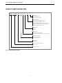
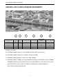
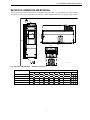
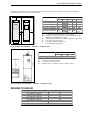
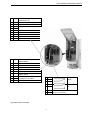
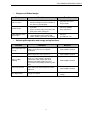
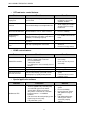
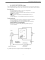
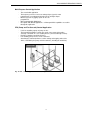
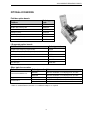
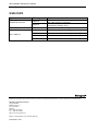
•
•
•
•
•
•
•
•
•
Trip free operation with safety switch
Silent motor operation with 10 kHz switching
frequency
Over temperature Ride Through
Power Ride Through
Integrated PID controller
Special application software capabilities
Stand-Alone cabinet design with units higher than
160kW (smaller powers as wall mounted)
Integrated PFC (Pump & Fan Cascade) –Controller
The best available fully controlled pump cascade
system with special software - Multimaster PFC
Mains Connection
Input voltage Uin
380…500 Vac (-15 …+10%) 3~
Input Frequency
Connection to mains
45...66 Hz
Once per minute or less
Motor Connection
These variable frequency drives provide step less speed
control for all open loop (no speed feedback from motor)
applications in HVAC and industrial environments:
•
Pumps
•
Fans
•
Compressors
•
Conveyors
•
Lifts
•
Escalators
•
Mixers
•
•
•
•
•
•
•
Most compact size in the market (especially IP54)
Integrated RFI-filters and AC-chokes
Application adapting Start Up Wizard
Application adapting Quick menu
Flexible “ALL IN ONE” multipurpose software with
predefined applications
Alphanumeric keypad with memory and backup
functions
Easy “keypad – remote” change with 1 button
® U.S. Registered Trademark
Copyright © 2011 Honeywell Inc. • All rights reserved
Output voltage
0…Uin
Continuous output current:
Low overload
IL: +40°C, overload 1.1 x IL
(for Fan/Pump)
(1min/10min)
High overload
(for machines)
IH: +50°C, overload 1.5 x IH
(1min/10min)
Starting Torque:
Low overload
(for Fan/Pump)
150%
High overload
(for machines)
200%
Starting Current
Output Frequency
2xIH for 2s/20s
0…320 Hz; up to 7200 Hz with
special software
0,01 Hz
Frequency resolution
EN0B0620GE51 R0611
NXS VARIABLE FREQUENCY DRIVES
Control Characteristics
Enclosure class
Control Method
Frequency Control U/f
Open Loop Sensorless Vector
Control
IP21 : NXS___ V35A2…
IP54 : NXS___ V35A5…
Enclosure type
Switching Frequency:
FR4 – FR6 (1.1-30kW)
NXS0003…- NXS0061…
1...16 kHz;
Default: 10 kHz (no derating)
NXS0003…- NXS0310…
FR7 – FR11 (37-400 kW)
NXS0072…- NXS0730…
1…10 kHz
Default: 3.6 kHz
Standard in 200-400 kW
Stand-Alone cabinet design
NXS0385…- NXS0730…
IP21 and IP54 (up to 250 kW)
Frequency reference:
Analogue input
Standard in 1,1-160 kW
Electro Magnetic Compatibility (EMC)
Resolution 0.1% (10bit),
accuracy ±1%
Keypad reference
Resolution 0.01 Hz
Field Weakening point
Acceleration time
Deceleration time
Braking torque
8…320 Hz
0…3000 sec
0…3000 sec
DC-brake: 30%*TN (without
brake option)
Immunity
Ambient Conditions
Ambient operating Temperature:
Low overload
–10°C (no frost)…+45°C
(for Fan/Pump)
(with 24h average +40°C)
Storage temperature
Relative humidity
Air quality:
Chemical vapors
EMC-level H: EN 61800-3
NXS0003…- NXS0310…
(2004) Category C2
Standard in 200-400 kW
EMC-level L: EN 61800-3
NXS0385…- NXS0730…
(2004) Category C3
EN60204-1, CE, EN61800-5
Control connections
Analogue input voltage
0...+10V, Ri = 200k ,
Resolution 10 bit,
accuracy ±1%
100% load capacity (no
derating) up to 1000m
1-% derating for each 100m
above 1000m; max. 3000m
Analogue input current
Digital inputs
0(4)…20 mA, Ri = 250
differential resolution 0.1%,
accuracy ±1%
6 positive logic; 18…24VDC
0…95% RH, non-condensing,
non-corrosive, no dripping
water
Auxiliary voltage
+24V, ±15%, max. 100mA
Altitude
Shock:
EN50178, IEC 68-2-27
Emissions:
Standard in 1.1-160 kW
(see unit nameplate for more detailed approvals)
IEC 721-3-3, unit in operation,
class 3C2
IEC 721-3-3, unit in operation,
class 3S2
Vibration:
EN50178/EN60068-2-6
EN61800-3 (both industrial and
public electrical network
requirements fulfilled as
standard)
Safety
–40°C…+70°C
0…95% RH, non-condensing,
non-corrosive, no dripping
water
Mechanical particles
Relative humidity
Wall mounted IP21 and IP54
Output reference voltage +10V, +3%, max. load 10mA
5...150 Hz
Displacement amplitude
1(peak) mm at 5...15.8 Hz
Max acceleration amplitude 1
G at 15.8...150 Hz
UPS Drop Test (for applicable
UPS weights)
Storage and shipping: max 15
G, 11 ms (in package)
2
Analogue output
0(4)…20mA; RL max. 500 ;
resolution 16 bit; accuracy
±1%
Relay outputs
2 programmable change over
relay output (1 NO/NC and 1
NO). Switching capacity:
24VDC/8A, 250VAC/8A,
125VDC/0.4A. Min.switching
load: 5 V/10 mA
NXS VARIABLE FREQUENCY DRIVES
Digital output
Motor thermistor Input
Open collector output
50 mA/48 V
Rtrip = 4.7 k (PTC)
Galvanically isolated
Motor overload
YES
protection
Motor stall protection
(fan/pump blocked)
YES
Motor underload
YES
protection (pump dry /
belt broken detection)
Protections
Overvoltage protection
Short-circuit protection
911VDC
Undervoltage protection 333VDC
Earth-fault protection
of +24V and +10V
reference voltages
In case of earth fault in motor
or motor cable, only the
inverter is protected
Input phase supervision YES
Motor phase supervision YES
Overcurrent protection
Trip limit 4,0*IH
instantaneously
Unit overtemperature
YES
protection
3
YES
NXS VARIABLE FREQUENCY DRIVES
!!
"
#
$% !!
& &
'( )
*
#$%!!
& &
'(
)
+
#$%!!
& &
'(
) %
-.
/0 &
2
&
3$
!
$
!
!
! %
! %
+
,
1
!
$
!
4
!
!
1
15
2 &
& &6
6
)$
&!
2%
!"
4
!
7
- () 5 4
5
-( )
4
$ 1 !!
1 !
$
- , "
8
1 &$
Fig. 1. Product Identification Code
4
7/
&4
& 2
!4
NXS VARIABLE FREQUENCY DRIVES
Mains voltage 3~ 380-500 V, 50/60 Hz, Series NXS
Product type
Motor shaft power
Loadability
400V supply
Low
overload
(for Pump /
Fan) 40°C
P [kW]
High
overload
(for
Machines)
50°C P [kW]
High
Low
Rated
continuous
current
IL [A]
10%
overload
current
[A]
Rated
continuous
current
IH [A]
50%
overload
current
[A]
Mechanical
size
enclosure /
protection
class
Dimensions
WxHxD
[mm]
Weight
[kg]
NXS0003V35A2H1
NXS0004V35A2H1
NXS0005V35A2H1
NXS0007V35A2H1
NXS0009V35A2H1
NXS0012V35A2H1
NXS0016V35A2H1
NXS0022V35A2H1
NXS0031V35A2H1
NXS0038V35A2H1
NXS0045V35A2H1
NXS0061V35A2H1
NXS0072V35A2H0
NXS0087V35A2H0
NXS0105V35A2H0
NXS0140V35A2H0
NXS0168V35A2H0
NXS0205V35A2H0
NXS0260V35A2H0
NXS0310V35A2H0
NXS0385V35A2L0
NXS0460V35A2L0
NXS0590V35A2L0
NXS0650V35A2L0
NXS0730V35A2L0
1,1
1,5
2,2
3
4
5,5
7,5
11
15
18,5
22
30
37
45
55
75
90
110
132
160
200
250
315
355
400
0,75
1,1
1,5
2,2
3
4
5,5
7,5
11
15
18,5
22
30
37
45
55
75
90
110
132
160
200
250
315
355
3,3
4,3
5,6
7,6
9
12
16
23
31
38
46
61
72
87
105
140
170
205
261
300
385
460
590
650
730
3,6
4,7
6,2
8,4
9,9
13,2
17,6
25,3
34
42
51
67
79
96
116
154
187
226
287
330
424
506
649
715
803
2,2
3,3
4,3
5,6
7,6
9
12
16
23
31
38
46
61
72
87
105
140
170
205
245
300
385
520
590
650
3,3
5,0
6,5
8,4
11,4
13,5
18
24
35
47
57
69
92
108
131
158
210
255
308
368
450
578
780
885
975
FR4/IP21
FR4/IP21
FR4/IP21
FR4/IP21
FR4/IP21
FR4/IP21
FR5/IP21
FR5/IP21
FR5/IP21
FR6/IP21
FR6/IP21
FR6/IP21
FR7/IP21
FR7/IP21
FR7/IP21
FR8/IP21
FR8/IP21
FR8/IP21
FR9/IP21
FR9/IP21
FR10/IP21
FR10/IP21
FR11/IP21
FR11/IP21
FR11/IP21
128x292x190
128x292x190
128x292x190
128x292x190
128x292x190
128x292x190
144x391x214
144x391x214
144x391x214
195x519x237
195x519x237
195x519x237
237x591x257
237x591x257
237x591x257
291x758x344
291x758x344
291x758x344
480x1150x362
480x1150x362
595x2018x602
595x2018x602
794x2018x602
794x2018x602
794x2018x602
5
5
5
5
5
5
8,1
8,1
8,1
18,5
18,5
18,5
35
35
35
58
58
58
146
146
270
270
470
470
470
NXS0003V35A5H1
NXS0004V35A5H1
NXS0005V35A5H1
NXS0007V35A5H1
NXS0009V35A5H1
NXS0012V35A5H1
NXS0016V35A5H1
NXS0022V35A5H1
NXS0031V35A5H1
NXS0038V35A5H1
NXS0045V35A5H1
NXS0061V35A5H1
NXS0072V35A5H0
NXS0087V35A5H0
NXS0105V35A5H0
NXS0140V35A5H0
NXS0168V35A5H0
NXS0205V35A5H0
NXS0260V35A5H0
NXS0310V35A5H0
NXS0385V35A5L0
NXS0460V35A5L0
1,1
1,5
2,2
3
4
5,5
7,5
11
15
18,5
22
30
37
45
55
75
90
110
132
160
200
250
0,75
1,1
1,5
2,2
3
4
5,5
7,5
11
15
18,5
22
30
37
45
55
75
90
110
132
160
200
3,3
4,3
5,6
7,6
9
12
16
23
31
38
46
61
72
87
105
140
170
205
261
300
385
460
3,6
4,7
6,2
8,4
9,9
13,2
17,6
25,3
34
42
51
67
79
96
116
154
187
226
287
330
424
506
2,2
3,3
4,3
5,6
7,6
9
12
16
23
31
38
46
61
72
87
105
140
170
205
245
300
385
3,3
5,0
6,5
8,4
11,4
13,5
18
24
35
47
57
69
92
108
131
158
210
255
308
368
450
578
FR4/IP54
FR4/IP54
FR4/IP54
FR4/IP54
FR4/IP54
FR4/IP54
FR5/IP54
FR5/IP54
FR5/IP54
FR6/IP54
FR6/IP54
FR6/IP54
FR7/IP54
FR7/IP54
FR7/IP54
FR8/IP54
FR8/IP54
FR8/IP54
FR9/IP54
FR9/IP54
FR10/IP54
FR10/IP54
128x292x190
128x292x190
128x292x190
128x292x190
128x292x190
128x292x190
144x391x214
144x391x214
144x391x214
195x519x237
195x519x237
195x519x237
237x591x257
237x591x257
237x591x257
291x758x344
291x758x344
291x758x344
480x1150x362
480x1150x362
595x2018x602
595x2018x602
5
5
5
5
5
5
8,1
8,1
8,1
18,5
18,5
18,5
35
35
35
58
58
58
146
146
270
270
5
NXS VARIABLE FREQUENCY DRIVES
!
Fig. 2. EMC classes in practice
1
2
3
4
5
6
Residential Area
Commercial
Light Industry
Area
Heavy Industry
R
R
O
O
R
R
EMC levels
Hospital
Airport
C
O
O
H
R
R
L
T
R (IT Network)
O = Optional, R= Required
C = EN61800-3 [2004] Category C1 (only available with NXL HVAC inverter family)
H = EN61800-3 [2004] Category C2 (standard in NXS up to 160 kW)
L = EN61800-3 [2004] Category C3 (NXS units in 200 - 400 kW)
T = EN61800-3 [2004] IT network (e.g. ships) requirements fulfilled, size FR4-FR8 inverters (NXS0003NXS0205) can be easily converted to T-class from standard EMC class. Instructions for this can be
found from NX Series User’s Manual included in all NXS deliveries or downloaded from
http://inverter.ecc.emea.honeywell.com
6
NXS VARIABLE FREQUENCY DRIVES
The inverter can be mounted in either vertical or horizontal position on the wall or on the back plane of a cubicle. It shall be
fixed with four screws (or bolts, depending on the unit size). Lift units bigger than FR7 out of the package using a jib crane.
Ø
W2
D1
H1 H2
H3
W1
Ø
fr5ip21.fh8
Fig. 3. NXS FR4 – FR8 (NXS0003… - NXS0205...) dimensions
Type
NXS0003—NXS0012
NXS0016—NXS0031
NXS0038—NXS0061
NXS0072—NXS0105
NXS0140—NXS0205
W1
128
144
195
237
285
W2
100
100
148
190
255
H1
327
419
558
630
755
H2
313
406
541
614
732
7
Dimensions [mm]
H3
D1
292
190
391
214
519
237
591
257
721
312
∅
7
7
9
9
9
E1∅
3 x 28,3
2 x 37
3 x 37
3 x 47
3 x 59
E2∅*
1 x 28,3
NXS VARIABLE FREQUENCY DRIVES
Ø
D1
D2
H4
H3
W4
W4
W1
W3
W2
H2
H3
H1
D3
Fig. 4. NXS FR9 (NXS0260… - NXS0310...) dimensions
Type
NXS0260—NXS0310
W1
W2
W3
W4
480
400
165
9
H1
Dimensions [mm]
H2
H3
H4
D1
D2
D3
∅
1150
1120
362
340
285
21
721
205
Fig. 5. NXS FR10 -11 (NXS0385… - NXS0730...) dimensions (floorstanding units)
Type
Dimensions [mm]
W1
W2
W3
W4
H1
NXS0385—NXS0460
595
291
131
15
NXS0590—NXS0730
794
390
230
15
8
H2
H3
H4
D1
2018
1900
1435
512
602
2018
1900
1435
512
602
NXS VARIABLE FREQUENCY DRIVES
Enough free space shall be left above and below the inverter to ensure sufficient air circulation and cooling. You will find the
required dimensions for free space in the table below.
Type
NXS0003—NXS0012
NXS0016—NXS0031
NXS0038—NXS0061
NXS0072—NXS0105
NXS0140—NXS0205
A
20
20
30
80
80
Dimensions
B
C
20
100
20
120
20
160
80
300
150
80
300
NXS0260—NXS0310
50
80
C
B
A
A
A2
A2
B
A
A2
B
C
D
*
D
NK5_2
A2
400
(350*)
= clearance around the inverter (see also A2 and B)
= clearance needed on either side of the inverter for fan change
(without disconnecting the motor cables)
= distance from one inverter to another or distance to cabinet wall
= free space above the inverter
= free space underneath the inverter
= min. clearance for fan change
Fig. 6. NXS FR4 – FR9 (NXS0003… - NXS0310…) installation space
Type
NXS0385—NXS0730
A
B
C
D
50
60
80
100
200
250
A
800
Dimensions
B
200
C
20
= clearance in front of the inverter
= free space above the inverter
= distance from one inverter to another or distance to wall
Fig. 7. NXS FR10 – FR11 (NXS0385… - NXS0730…) installation space
!
Type
Cooling air required [m3/h)
FR4: NXS0003—NXS0012
FR5: NXS0016—NXS0031
FR6: NXS0038—NXS0061
FR7: NXS0072—NXS0105
FR8: NXS0140—NXS0205
FR9: NXS0260—NXS0310
FR10: NXS0385—NXS0460
FR11: NXS0590—NXS0730
70
190
425
425
650
1300
2600
3900
9
NXS VARIABLE FREQUENCY DRIVES
"
B- B+ R-
U/T1 V/T2 W/T3
L1 L2 L3
nxlk58.fh8
Fig. 8. NXS power connections FR4-FR6 in FR7-FR11 connectors B-, B+ and R- do not exist as standard.
Use cables with heat resistance of at least +70°C. The cables and the fuses must be dimensioned according to the tables
below. The fuses function also as cable overload protection. These instructions apply only to cases with one motor and one
cable connection from the inverter to the motor. In any other case, ask the technical support for more information.
Connection
Cable type
Mains cable
Power cable intended for fixed installation and the specific mains voltage. Shielded cable not required.
(NKCABLES/MCMK or similar recommended)
Motor cable
Power cable equipped with compact low-impedance shield and intended for the specific mains
voltage.(NKCABLES /MCCMK, SAB/ÖZCUY-J or similar recommended).
(360º earthing of both motor and FC connection required to meet the EMC requirements)
Control cable Screened cable equipped with compact low-impedance shield (NKCABLES /jamak, SAB/ÖZCuY-O or similar)
Frame
Type
IL
[A]
Fuse
[A]
Mains and motor cable
Cu [mm2]
FR4
NXS0003—NXS0009
NXS0012
NXS0016
NXS0022
NXS0031
3—9
12
16
22
31
10
16
20
25
35
3*1.5+1.5
3*2.5+2.5
3*4+4
3*6+6
3*10+10
NXS0038—NXS0045
38—45
50
3*10+10
NXS0061
61
63
3*16+16
NXS0072
72
80
3*25+16
NXS0087
87
100
3*35+16
NXS0105
105
125
3*50+25
NXS0140
NXS0168
NXS0205
NXS0260
NXS0310
NXS0385
NXS0460
NXS0590
NXS0650
NXS0730
140
168
205
261
300
385
460
590
650
730
160
200
250
315
315
400
500
630
800
800
3*70+35
3*95+50
3*150+70
3*185+95 or 2*(3*120+70)
2*(3*120+70)
2*(3*120+70)
2*(3*150+70)
2*(3*240+120)
4*(3*95+50)
4*(3*120+70)
FR5
FR6
FR7
FR8
FR9
FR10
FR11
10
Terminal cable size
Main terminal [mm2]
1—4
1—4
1—10
1—10
1—10
2.5—50 Cu
6—50 Al
2.5—50 Cu
6—50 Al
2.5—50 Cu
6—50 Al
2.5—50 Cu
6—50 Al
2.5—50 Cu
6—50 Al
25—95 Cu/Al
95—185 Cu/Al
95—185 Cu/Al
95—185 Cu/Al 2
95—185 Cu/Al 2
Earth terminal [mm2]
1—2.5
1—2.5
1—10
1—10
1—10
6—35
6—35
6—70
6—70
6—70
25—95
25—95
25—95
5—95
5—95
NXS VARIABLE FREQUENCY DRIVES
1
+10 Vref Reference output (voltage for
potentiometer etc.)
2 AI1 +
Analogue Input 1 (V signal)
3 AI1 –
I/O ground
Analogue Input 2 (mA signal)
4 AI2 +
5 AI2 –
6 +24 V +24 V input/output (max. 0.1 A)
7 GND
I/O ground
8 DIN1
Digital Input 1
9 DIN2
Digital Input 2
10 DIN3
Digital Input 3
11 CMA
12
13
14
15
16
17
+24 V
GND
DIN4
DIN5
DIN6
CMB
18 AO1 +
19 AO1 –
20 DO1
Digital input common for DIN1,
DIN2 and DIN3
Same as terminal 6
I/O ground
Digital Input 4
Digital Input 5
Digital Input 6
Digital input common for DIN4,
DIN5 and DIN6
Analogue output 1, default range:
0–20 mA/RL, max. 500 Ω
Open collector Output
21 RO1
22 RO1
23 RO1
Relay 1
NO/NC
25 RO2
26 RO2
Relay 2
NO
28 TI+
29 TI-
Fig. 9. NXS control connections
11
Thermistor Input;
Rtrip = 4.7 kΩ (PTC)
NXS VARIABLE FREQUENCY DRIVES
#
•
Easy to set-up and operate features
Alphanumeric keypad is included as standard
-
Clear text display with multilanguage support
Possibility to use real units in monitoring
Possibility to monitor 3 values simultaneously with Multimonitor
view
Password protection possible
Keypad equipped with memory and backup function
-
Keypad equipped with memory for uploading and downloading
parameters. Possibility to copy parameters from unit to unit with
standard keypad
Keypad can be used as a backup for parameter settings
Application adapting Start Up Wizard
-
Real text based wizard which guides the user through setup of
all applications easily
Start up wizard adapts to the application selected and guides the
operator to do the settings which are relevant for just the
application in question
Application adapting Quick Menu
-
Quick menu called “Basic Parameters- group” adapts to the application
selected
Includes always the relevant parameters for just the application in
question in to the group
“Keypad – Remote” Operation
-
Single button operation to change the control to manual (keypad)
and back
Useful function when commissioning and testing HVAC
applications.
Consistency: all Honeywell VFDs behave in similar way
Press
LEFT ARROW for 3 s to
change control place
12
NXS VARIABLE FREQUENCY DRIVES
•
Compact and Robust design
Features
Enclosure Class
Functions
•
•
•
Modular design
Built in input AC choke
and RFI filter
•
•
•
•
•
•
NXS available with both IP21 and IP54
Smallest and lightest inverter available in
the market (especially IP54)
Separated cooling channel (no electronics
in air flow)
Power electronics fully enclosed in metal
Easily replaceable cooling fans
Protection against input voltage surges
Lower total harmonic distortion THD
Fulfills all EMC requirements in buildings
Benefits
•
•
Consumes less space
Easy to install
•
•
Increased reliability
Easy maintenance
•
•
Compact
No additional costs
Uninterruptible operation and energy saving functions
Features
Functions
Benefits
Over Temperature ride
through
Automatically adjusts switching frequency to
adapt to unusual increase in ambient
temperature
•
Uninterruptible operation
Power ride through
Automatically lowers motor speed to adapt to
sudden voltage drop such as power loss
•
Uninterruptible operation
•
Uninterruptible operation
•
Uninterruptible operation
•
Even 5% increase in energy
savings.
Tripless output
switching
Auto restart function
Energy Saving Function
“Flux Optimization”
Ensures tripless operation when an output
switch (e.g. safety switch) is operated
between the motor and the VFD. Truly
intelligent and highly reliable function to
ensure better functionality than with any other
VFD
Auto restart function can be configured to
make VFD restart automatically once fault is
addressed
Flux Optimization automatically minimizes
energy consumption.
13
NXS VARIABLE FREQUENCY DRIVES
•
VFD and motor control features
Features
Functions
Best in performance
Flying start
Ability to get an already spinning fan under
speed control
Automatic torque boost
function
Boosts initial voltage to start high inertia fans
Benefits
•
Important in clean room
production to ensure the
standard conditions
•
Avoids tripping and enables
smooth starts also to high
inertia loads
Motor auto identification
Performs measurements to find out motor
internal variables such as stator resistance.
•
Increases reliability
High Switching
Frequency
Honeywell NXS has higher switching
frequency than the most of the competition as
standard (= no derating required)
•
Less audible noise from the
motor
Prohibit frequency
Overriding the critical frequencies to avoid
resonance
•
Elimination of resonance
Temperature-controlled
fans
Fan stops operating when not needed
•
Less audible noise from
VFD itself
Increase of energy savings
•
•
HVAC control features
Features
Functions
•
•
Sleep Mode
Fire override mode
Normal and Inverse Regulation
Delta P regulation with 2 standard
pressure transmitters
• Volume flow control
• Less wiring since sensor normally close to
inverter
Shutting down the motor, when no demand
Keeps fan/pump running in case of fire
PFC (Pump and Fan
Cascade) -Controller
Controls total pumping system with several
parallel pumps by equally sharing the load
Inbuilt PID controllers
•
Benefits
•
•
Cost savings
Faster response in process
closed loop
•
•
•
Saves energy
Legal requirement
Longer lifetime of the
system
Lower investment cost for
pumping system
•
Special application software
Features
Functions
•
Multimaster PFC
•
•
•
•
•
The best available fully controlled pump
cascade VFD system in the market
System with a VFD for each pump
Only 2 wires needed for the connection
between inverters – no additional
hardware
Full control over the total pumping system
Equal usage of each pump
Fully redundant system
14
Benefits
•
•
•
•
Longer lifetime of the
system
Increased reliability
Increased energy savings
with optimized usage of
pumps
Fully independent pump
control system can be
created for pumping
stations
NXS VARIABLE FREQUENCY DRIVES
•
“ALL IN ONE” MULTIPURPOSE software
Flexible “ALL IN ONE” multipurpose software offers predefined applications as described below for different kind of
needs. This flexible package really makes it possible to answer any needs from the application with Honeywell NXS.
Basic application
-
The most typical choice for HVAC - covers most of the applications
Everything needed for basic speed control
Includes only one small group of parameters with default values to create simple
selection
Very simple commissioning
The control signals of this application are fixed with default functions (not
configurable)
The Basic Application is set as the default when the drive leaves the factory.
Standard application
-
nd
The 2 most typical choice for HVAC - extended version of the basic application
For more demanding cases where more functionality is required
The Standard Application has the same I/O-configuration and control logic as
the Basic application - i.e. no rewiring needed.
All inputs and all outputs are freely configurable
More functions, e.g. dynamic braking, DC braking, Prohibit Frequency for
resonance elimination
Motor
Pump
or
Load
Fan
Sensor
Speed Signal
V signal to AI1
mA signal to AI2
Variable Frequency Drive
Control System
Fig. 10. Basic speed control – the typical use of basic and standard application
15
NXS VARIABLE FREQUENCY DRIVES
Local/Remote application
-
The Local/Remote Control Application can be used in applications where the
drive must be controlled from two different locations. control logic as the Basic
application - i.e. no rewiring needed.
The control locations (A&B) are programmable and can be selected via digital
inputs.
There can be separate references for operation and Start/Stop-inputs
All inputs and all outputs are freely configurable
Multi-Step Speed Application
-
-
The Multi-Step Speed Control Application can be used in applications where
multiple fixed speeds are required.
A total of 15 +2 speeds are available:
o one basic speed (analogue voltage or current)
o 15 multi-step speeds
o one jogging speed.
Selection of the speeds is via digital inputs.
Mechanical brake control available.
All inputs and outputs are freely configurable
PID-Control Application
-
The PID Control Application can be used where there is a need to keep a
constant temperature or pressure etc.
2 control locations available (by-pass of regulator possible)
Source A is PID-controller
o analogue input or a mathematical function of the analogue inputs
Source B is a direct speed reference
o analogue input, a motorized potentiometer or control panel
Stable control for a variety of tasks
All inputs and outputs are freely configurable
Pump
Motor
or
Load
Fan
Actual value
Sensor
Setpoint Signal
Variable Frequency Drive
Control System
Fig. 11. PID – Control with Variable frequency drive
16
NXS VARIABLE FREQUENCY DRIVES
Multi-Purpose Control Application
-
The most flexible application
The frequency reference can be an analogue input, joystick, motor
potentiometer or a mathematical function of the analogue inputs.
Multi-step speeds or jogging speed can also be
programmed.
More programmable digital inputs
Best option with difficult applications – all Honeywell NXS capabilities accessible
through this application
PFC (Pump and Fan Cascade) Control Application
-
Used for controlling a group of pumps or fans.
The internal PID regulator controls the speed of one motor and provides
start/stop commands for 1 to 4 auxiliary motors (connected directly to mains)
Provides redundancy and high efficiency.
Four auxiliary pumps or fans can be connected
Autochange (if activated) allows to set the starting and stopping order of the
drives, controlled by the pump and fan automatics (including the main drive)
EXTERNAL
CONTACTORS
Fig. 12. PFC- controller application with autochange
17
NXS VARIABLE FREQUENCY DRIVES
•
Optional application software
Several special application software are available for download form Honeywell support web
site free of charge. And also special features can be created with the built in PLC if required.
In below there is presented one of the most commonly used special applications Multimaster
PFC. Special software can be downloaded from: http://inverter.ecc.emea.honeywell.com
Multimaster PFC (Pump and Fan Cascade) Application
-
Dedicated solution for parallel pumping applications
Unique on the market
Replaces traditional contactor systems and can perfectly work as a stand alone
system
Fully integrated in VFD
Only 2 wire connection required between inverters - no additional hardware
Recommended for main pumping, booster stations, watering systems, sewage
water pumping stations
Adds reliability, minimizes risk for interruptions, fully redundant
Functionality: PID, Autochange anytime, Sleep function
Fig. 13. Multimaster PFC system
-
One NXS Inverter for each pump
Integrated control of 2-3 pumps
Redundant system
Higher Efficiency at low consumption hours
Automatic alternation without pressure spikes
Individual or common pressure sensor
Fewer parts than normal PFC application
Uses Interlocks to take out pumps for service
18
NXS VARIABLE FREQUENCY DRIVES
-
Field bus option boards
Fieldbus
Order type
code
LonWorks
OPTC4
Modbus RTU, Metasys N2
NXOPTC2
Profibus DP
NXOPTC3
CANopen (slave)
NXOPTC6
Devicenet
NXOPTC7
Modbus/TCP (Ethernet)
NXOPTCI
Bacnet MS/TP
NXOPTCJ
I/O expander option boards
Additional I/O
Order type code
6 Digital Inputs/Outputs (programmable)
OPTB1
1 Analogue Input (mA), 2 Analogue Output (mA)
OPTB4
3 Relays
OPTB5
1 Relay, 5 Vac inputs (42-240 Vac)
OPTB9
2 Relays, 1 Thermistor
NXOPTB2
3 Pt100 inputs
NXOPTB8
Other typical accessories
Option
Order type code Note
DRA02B
NXS Door installation set for display panel, 2m cable
DRA-04B
NXS Door installation set for display panel, 4m cable
Keypad
NXPANG
NXS graphical keypad (for Chinese and Cyrillic letters)
RS232 Cables*
RS232C2M
RS232C-4M
2m RS232 serial link cable for PC connection
4m RS232 serial link cable for PC connection
Panel door installation sets
* NXS has standard RS232 connection so no additional adapters are required
19
NXS VARIABLE FREQUENCY DRIVES
Type
Standard I/O spareparts
Keypad spareparts
Main cooling fans
Order type code Note
NXPANA
Standard I/O replacement for:
6DI, 1DO, 2AI(mA/V), 1AO(mA/V)
Standard I/O replacement for:
1RO(NO/NC),1RO(NC),Therm
NXS standard alphanumeric keypad
NX-FAN-4
FR4 (NXS0003-0012) main cooling fan assembly
NX-FAN-5
FR5 (NXS0016-0031) main cooling fan assembly
NX-FAN-6
FR6 (NXS0038-0061) main cooling fan assembly
NX-FAN-7
FR7 (NXS0072-0105) main cooling fan assembly
NXOPTA1
NXOPTA3
!
Automation and Control Solutions
Honeywell GmbH
Böblinger Straße 17
71101 Schönaich
Germany
Phone: (49) 7031 63701
Fax: (49) 7031 637493
http://ecc.emea.honeywell.com
Subject to change without notice. Printed in Germany
EN0B0620GE51 R0611
" #
# $ %& % ' ( )
*+#
,
&
,
-
..