1
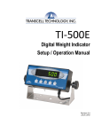
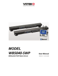
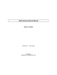
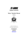
ITI-500E
INSTRUCTION MANUAL
WEIGHING INDICATOR TI-500 E
Vetek AB Box 79
760 40 Väddö Sweden
Tel +46 176 50825
Fax +46 176 52395
e-mail [email protected]
www. weighingblock.com
2000-10-10
TI-500/500E Setup/Operation Manual 1
Table of Contents
Introduction......................................................................................................................................... 1
Keyboard Functions............................................................................................................................. 2
Installation and Wiring ....................................................................................................................... 3
Configuration ...................................................................................................................................... 3
Setup Menu Descriptions..................................................................................................................... 6
User Menu Descriptions ...................................................................................................................... 7
Calibration .......................................................................................................................................... 9
APPENDIX A: Specifications.............................................................................................................. 13
APPENDIX B: Serial Port Modes & Cable Diagrams .......................................................................... 14
APPENDIX C: Determining Proper Span Gain ................................................................................... 17
APPENDIX D: Options....................................................................................................................... 18
APPENDIX E: Displayed Error Codes ................................................................................................ 19
Introduction
The TI-500 is a general purpose, "no frills" digital
indicator housed in a standard black ABS enclosure. It
comes standard with a large (.75") LCD screen for
easy readout of up to 50,000 display divisions, and
supplies enough current for up to 4-350? load cells.
All setup parameters may be entered via the front
panel keys, including calibration.
communication with personal computers or remote
displays and a special Gross/Net/Tare mode for direct
connection to a printer. In full duplex mode, the unit
can transmit data on demand, or continuously in a
popular data protocol.
The indicator's setup parameters are altered through the
Setup menu while the serial communication
Its sister indicator, the TI-500E, features a green LED parameters are altered through the User menu The
screen for use in poorly lit areas. Function-wise the TI- configuration section of the manual, starting on page 2,
explains how to use the five front panel keys to
500E is the same as the TI-500.
maneuver and save settings in both menus.
The TI-500 has two RS-232C communication modes:
full duplex serial format for communication
Keyboard Functions
lb
kg
Toggles between lb and kg units
if this key is enabled in the User
Menu.
pcs
O
lb oz
TE
kg %
G
ZERO
NET
GROSS
Sets indicator to display "0"
when in Gross mode, and within
zero band range.
Toggles between Gross and Net
weight display only if a Tare has
been established.
LO
N
nmax = 5000
CLASS III
lb
kg
HI
OK
ZERO
NET
GROSS
TARE
PRINT
MODEL
Transcell Technology
TI-500
TI-500 FRONT PANEL
TARE
Used to establish a Tare while in either Gross mode or Net mode. This operation cannot be performed at or below
Gross zero.
PRINT
Sends "Print" data to printer if scale is stable and not in overload. Not active when "Continuous" option is selected in
User Menu.
2 Revision Vetek OV 001010
Installation and Wiring
Following is the Installation and Wiring directions for the standard TI-500/500E indicator only. If the
indicator was ordered in the stainless steel enclosure, please refer to Appendix D for wiring information.
The TI-500's back cover comes equipped with a
female DSUB-9 connector for the RS-232 serial port,
a male input jack for DC power, a calibration switch,
and a female 14-pin Centronics type connector for
input of the 15’ 4-wire load cell cable, included. See
below for wiring and color code information.
Shown at right are the color codes
for the 15’ load cell cable. You
may wire this cable to your load
cell or junction box. Or you can
wire your own cable (see below).
Shown at right are the pin
assignments for the female 14-pin
load cell connector. Please wire
cable to both pins listed to ensure
proper operation.
Shown at right are the pin
assignments for the female 9-pin
RS-232 connector. For suggested
cable diagrams, see Appendix B.
Color
Setup/Calibration
Switch
Power Switch
DC Jack
LOAD CELL
Connector
RS 232
Wire Name
RED
BLK
GRN
WHT
+Excitation
Pin Nos.
Pin Name
–Excitation
+Signal
–Signal
1/8
3/10
5/12
7/14
+Excitation
Pin No.
Pin Name
2
3
5
Receive Data
Transmit Data
Signal Ground
–Excitation
+Signal
–Signal
7
5
3
1
14
12
10
8
14-pin load cell connector (female)
5
3
2
9-pin RS-232 connector (female)
Configuration
The TI-500 indicator includes two separate menus
which contain all of the configurable parameters for
the unit. The Setup menu, containing most of the
indicator's functional setup parameters, consists of 15
separate menu selections, each with its own sub-menu
of choices. The User menu, containing most of the
indicator's serial communication parameters, consists
of 9 separate menu selections, each also with its own
sub-m
own sub-menu of choices.
To set up the indicator, you must first enter the
appropriate menu mode. Once there, four of the front
panel keys become directional navigators to move
around in the menus, and one key is used to save or
SET the selections. Complete directions for the
standard indicator start on the next page.
TI-500/500E Setup/Operation Manual 3
Configuration / Continued
To place the unit in Setup menu mode:
Note: If the indicator was ordered in the stainless steel enclosure, please refer to Appendix D for
instructions on how to enter setup mode.
1. Turn the power off to the unit.
2. On back cover, move the Setup /
Calibration Switch to opposite
position. Turn the indicator back on.
3. The display shows "F1" to indicate
that the unit is in Setup menu mode.
Shown at right are the directional
and SET key assignments.
SET
SETUP MENU CHART
F1
Grads
F2
Span Gn.
F3
Zero Band
0d 0.5d 1d
F4
Zero Range
3d 5d
F5
Mot. Band
F7
Ovld. Limit
F8
Calib. Unit
0d 2% 1d 9d
1d 3d 5d 10d
100% 1.9%
25 50 75 100 150 200
F6
Dig. Filter
1 2 4 8
lb kg
500 1000 1500 2000 2500 3000 4000 5000 6000 8000 10000 12000 20000 30000 40000 50000
F9
Dsp. Div.
1
2
F10
Dec. Pt.
5
F16
Zero Calib.
F17
Span Calib.
Press ZERO
key to begin
Press ZERO
key to begin
F18
Cal. View
Press ZERO
key to begin
F19
Key-in Zero
F20
Key-in Span
Press ZERO
key to begin
Press ZERO
key to begin
0 0.0 0.00 0.000 0.0000 00
Notes on SETUP MENU CHART:
1.
Functions F11 to F15 are reserved for future use and do not appear when toggling from F10 to F16.
2.
Detailed descriptions of the menu parameters begin on page 5 of this manual.
4 Revision Vetek OV 001010
Configuration / Continued
To place the unit in User menu mode:
1. Turn the power off to the unit.
2. While holding down the lb/kg key,
turn the power back on.
3. When the display shows "A1", the
unit is in User Menu mode, and you
can release the lb/kg key. Shown at
right are the directional and SET key
assignments
SET
USER MENU CHART
A1
Baud Rate
A2
Data Bits, Parity
A3
Transmission Mode
8n 7O 7E
C
A4
Display Check
A5
Enable lb/kg Key
Press ZERO
key to begin
d
0 1
1200 2400 4800 9600
A6
Serial Port Mode
0
1
A7
ID No. Enable
0
1
A8
ID No. Entry
Press ZERO
key to begin
A9
No. of Line Feeds
Press ZERO
key to begin
To place the unit back into the Normal Operating mode:
1. Turn off the indicator. If the unit was in Setup menu mode, toggle the Setup/Calibration Switch back to its original
position, and turn the indicator on. If the indicator was in User menu mode, just turn the indicator back on without
pressing any keys.
2. The display will go through a digit check, then settle into Normal Operating mode.
3. All front panel keys will now return to their normal mode of operation.
TI-500/500E Setup/Operation Manual 5
Setup Menu Descriptions
NAME/CODE
DESCRIPTION
CODE/VALUE
F1
Graduations
Specifies number of full scale graduations. Value should be consistent with
legal requirements and environmental limits on the useful system resolution.
500
1,500
2,500
4,000
6,000
10,000
20,000
40,000
F2
Span Gain
Span Gain is related to A/D integration time. The larger the span gain, the
higher the internal resolution, but the slower the update speed. See Appendix
C for more information.
25
75
150
F3
Zero Track
Band
Selects the range within which the scale will automatically zero. Note that
the scale must be in standstill to automatically zero. Selections are in
Display Divisions.
0d
0.5d?
1d
3d
5d
F4
Zero Range
Selects the range within which the scale may be zeroed. Note that the
indicator must be in standstill to zero the scale.
100%?
1.9%
F5
Motion Band
Sets the level at which motion is detected by comparing the present display
update with the previous one. If motion is not detected for two seconds or
more, scale is in standstill and can process a Print or Zero command.
Maximum value varies depending on local regulations.
1d
3d?
5d
10d
F6
Digital Filter
Averages weight readings to produce higher accuracy. The higher the filter
number, the greater the accuracy but the slower the response time. Choose 4
or 8 unless a very fast response is needed.
1
4
F7
Overload Limit
Selects the desired formula which determines the point at which the
indicator shows overload ("? ? ? ? "). All selections are based on the
primary unit selected in F8.
FS
FS + 2%?
FS + 1d
FS + 9d
"FS" = Full scale in primary units.
1,000
2,000
3,000
5,000?
8,000
12,000
30,000
50,000
50?
100
200
2
8?
F8
Calib. Unit
Selects the primary base unit to be used in the calibration process. Also the
default unit for normal operation.
"1" = primary unit is lb.
"2" = primary unit is in kg.
1?
2
F9
Display
Divisions
Determines the desired weight increments. Value should be consistent with
legal requirements.
1?
2
5
F10
Decimal Pt.
Determines location of the decimal point.
0?
0.00
0.0000
F16
Zero Calibration
Places indicator into the zero calibration routine. Scrolling down with the
ZERO key one level begins the procedure.
Press ZERO key to
begin sequence
6 Revision Vetek OV 001010
0.0
0.000
00
Setup Menu Descriptions / Continued
NAME/CODE
DESCRIPTION
CODE/VALUE
F17
Span Calibration
Places indicator into the span calibration routine. Scrolling down with the
ZERO key one level begins the procedure.
Press ZERO key to
begin sequence
F18
View Calibration
Actuates the function which allows user to view both the zero and span
calibration value. The values displayed in this function are valid only after
Calibration (F16 & F17) has been successfully completed. Scrolling down
with the ZERO key one level begins the procedure.
Press ZERO key to
begin sequence
F19
Key-in Zero
Allows user to key-in known zero calibration value in case of memory loss
in the field. Scrolling down with the ZERO key one level begins the
procedure.
Press ZERO key to
begin sequence
F20
Key-in Span
Allows user to key-in known span calibration value in case of memory loss
in the field. Scrolling down with the ZERO key one level begins the
procedure.
Press ZERO key to
begin sequence
Notes on Setup Menu Descriptions:
Factory-set defaults are shown in bold with a ? .
User Menu Descriptions
NAME/CODE
DESCRIPTION
CODE/VALUE
A1
Baud Rate
Selects the baud rate for data transmission through the serial port.
1200
4800
A2
Data Bits and
Parity
Selects the number of data bits and parity of serial transmission.
"8n" = 8 data bits with no parity bit
"7O" = 7 data bits with odd parity bit
"7E" = 7 data bits with even parity bit
8n?
7O
7E
A3
Mode of Serial
Transmission
Selects when data will be sent out of the serial port to a printer or computer:
"C" = Continuous mode; send data continuously
"d" = Demand mode; send data when a PRINT command is issued from the
printer, computer, or indicator.
C?
d
A4
Display Check
Actuates the function which illuminates all digit segments, decimal points,
and LCD annunciators in a test sequence. Pressing the ZERO key to scroll
down one level begins the test sequence.
Press ZERO key to
begin sequence
A5
Disable the
lb/kg Key
Allows the lb/kg key to be disabled so that an operator cannot accidentally
press the key and change the displayed units.
"0" = Disable the lb/kg key
"1" = Enable the lb/kg key
0
1?
2400?
9600
TI-500/500E Setup/Operation Manual 7
User Menu Descriptions / Continued
NAME/CODE
DESCRIPTION
CODE/VALUE
A6
Serial Port
Mode
Selects the mode of the RS-232C serial port:
"0" = Full Duplex Mode
"1" = Gross/Net/Tare Print Mode
0?
1
A7
ID No. Enable
Allows the ID No. to be disabled in the Gross/Net/Tare printout. Valid only
when A6 is set to “1“.
"0" = Disable the ID No.
"1" = Enable the ID No.
0
1?
A8
ID No. Entry
Actuates the function which allows entry of a new ID No. Valid only when
A6 is set to “1“. Pressing the ZERO key to scroll down one level begins the
sequence.
0? - 199999
(TI-500)
0? - 999999
(TI-500E)
A9
No. of Line
Feeds
Actuates the function which allows entry of the desired number of line feeds
to be printed after the Gross/Net/Tare printout. Valid only when A6 is set to
“1“. Pressing the ZERO key to scroll down one level begins the sequence.
0? - 99
Notes on User Menu Descriptions:
Factory-set defaults are shown in bold with a ? .
8 Revision Vetek OV 001010
Calibration
Note: If the indicator was ordered in the stainless steel enclosure, please refer to Appendix D for
instructions on how to enter Setup mode.
Power Switch
DC Jack
Setup/Calibration
Switch
RS 232
LOAD CELL
Connector
SET
The indicator is calibrated by following the procedures both calibration values, which can be viewed by
embedded in F16 (Zero) and F17 (Span) of the Setup entering the F18 View procedure.
Menu. Each procedure enters a value into the
In the unlikely event that either value is lost while in
indicator's non-volatile memory; F16 the zero value
the field, the setup menu makes provisions for re(deadweight) and F17 the span value (test weight).
entering these values via F19 and F20, thus eliminating
The minimum test weight that can be used is 1% of
the need for re-calibration with test weights.
full scale capacity. After the two calibration procedures
are executed successfully, the user should record both
calibratio
To calibrate the zero point using the F16 zero calibration procedure:
1. If the unit is not in the Setup mode, enter the Setup mode as follows: Turn the power off to the unit. On the back
cover, move the Setup / Calibration Switch to opposite position. When power is re-applied, "F 1" shows on the
display. Allow a 20 minute warm-up period for the load cell(s) and indicator to become thermally stable.
2. While in the Setup mode, scroll to "F 16", then scroll down once using the ZERO key to enter zero calibration menu.
The display will momentarily show "C 0" followed by a value. This value is the internal A/D count and can prove
useful when trying to troubleshoot setup problems.
3. After making sure that there are no test weights on the platform, press ZERO to zero the value, then press the
NET/GROSS key to save the zero point value.
4. The display will show "EndC0" momentarily, then revert back up to F16. At this time, proceed to the F17 span
calibration to complete indicator calibration.
TI-500/500E Setup/Operation Manual 9
Calibration / Continued
To calibrate the span using the F17 span calibration procedure:
1. While in the Setup mode, scroll to "F 17", then scroll down once using the ZERO key to enter span calibration menu.
2. The display will momentarily show "C 1" for the span calibration, followed by a value with one flashing digit. This
value will be zero with the Decimal Point parameter selected in F10. Place the test weight on the weighing
mechanism.
3. Use the four directional keys (shown at right) to adjust the
displayed value to the actual test weight value. Increase the
flashing digit by pressing the lb/kg key. Decrease the
flashing digit by pressing the ZERO key. The position of
the flashing digit may be changed by pressing the PRINT
key or the TARE key.
SETUP MODE KEY FUNCTIONS
lb
kg
ZERO
NET
GROSS
TARE
PRINT
SET
4. After setting the exact value, press the NET/GROSS key to save the value.
5. If the calibration was successful, the display will show "EndC1" momentarily, then revert back up to F17. At this
time it is suggested that the calibration values be recorded for future use (see next page).
6. If the calibration was not successful, one of the error messages below will appear. Take the indicated action to correct
the problem, then perform a new calibration.
"Err0" - The calibration test weight or the adjusted keyed-in weight is larger than the full capacity of the scale.
Change the calibration test weight or check the input data.
"Err1" - The calibration test weight or the adjust keyed-in weight is smaller than 1% of the full capacity of the scale.
Change the calibration test weight or check the input data.
"Err2" - The internal resolution of the scale is not high enough to accept the calibration value. Select a larger
parameter for the Span Gain (F2).
10 Revision Vetek OV 001010
Calibration / Continued
To record the calibration values using the F18 View Procedure:
Note: The values displayed in this procedure are valid only after a successful calibration has been performed using F16
and F17.
1. If the unit is not in the Setup mode, enter the Setup mode as follows: Turn the power off to the unit. On the back
cover, move the Setup / Calibration Switch to opposite position. When power is re-applied, "F 1" shows on the
display.
2. While in the Setup mode, scroll to "F 18", then scroll down once using the ZERO key to enter View calibration
menu.
3. The display will momentarily show "CAL 0" followed by a value. This value is the zero calibration value and
should be recorded in the table below. Press any key to continue.
4. The display will momentarily show "CAL 1" followed by another value. This value is the span calibration value
and should also be recorded in the table below. Press any key to return to upper level (F18).
TI-500 INDICATOR
ZERO CALIBRATION
VALUE
SPAN CALIBRATION
VALUE
S/N:
TI-500 Calibration Value Table
To key-in the zero calibration value using the F19 Key-in Procedure:
Note: This procedure is intended for emergency use only in the case of non-volatile memory loss. A valid zero calibration
value, obtained from a successful F16 calibration procedure, must be used.
1. If the unit is not in the Setup mode, enter the Setup mode as follows: Turn the power off to the unit. On the back
cover, move the Setup / Calibration Switch to opposite position. When power is re-applied, "F 1" shows on the
display.
2. While in the Setup mode, scroll to "F 19", then scroll down once using the ZERO key.
3. The display will momentarily show "CAL 0", followed by
a flashing zero. Use the four directional keys (shown at
right) to adjust the displayed value to the zero calibration
value.
SETUP MODE KEY FUNCTIONS
lb
kg
ZERO
NET
GROSS
TARE
PRINT
SET
4. After setting the exact value, press the NET/GROSS key to save the value.
5. The display will show "E CAL 0" momentarily, then revert back up to F19.
TI-500/500E Setup/Operation Manual 11
Calibration / Continued
To key-in the span calibration value using the F20 Key-in Procedure:
Note: This procedure is intended for emergency use only in the case of non-volatile memory loss. A valid span
calibration value, obtained from a successful F17 calibration procedure, must be used.
1. If the unit is not in the Setup mode, enter the Setup mode as follows: Turn the power off to the unit. On the back
cover, move the Setup / Calibration Switch to opposite position. When power is re-applied, "F 1" shows on the
display.
2. While in the Setup mode, scroll to "F 20", then scroll down once using the ZERO key.
3. The display will momentarily show "CAL 1", followed by
a flashing zero. Use the four directional keys (shown at
right) to adjust the displayed value to the span calibration
value.
SETUP MODE KEY FUNCTIONS
lb
kg
ZERO
NET
GROSS
TARE
PRINT
SET
4. After setting the exact value, press the NET/GROSS key to save the value.
5. If the entered value is greater than zero, the display will show "E CAL 1" momentarily, then revert back up to F20. If
a value of zero is entered, the indicator will briefly show "Err 5", then revert back to the screen described above in
Step # 3.
To place the unit back into the Normal Operating mode:
1. Turn off the indicator. Toggle the Setup/Calibration Switch back to its original position, and turn the indicator back
on.
2. The display will go through a digit check, then settle into Normal Operating mode.
3. All front panel keys will now return to their normal mode of operation.
12 Revision Vetek OV 001010
APPENDIX A: Specifications
ANALOG SPECIFICATIONS
Full Scale Input Signal
Minimum Sensitivity - Non H-44
Minimum Sensitivity - H-44
Input Impedance
Internal Resolution
Display Resolution
Measurement Rate
System Linearity
Calibration Method
Excitation Voltage
30mV, including dead load
0.4 ? V / grad
1.0 ? V / grad
30M? , typical
Approximately 260,000 counts
30,000 dd
10 Meas/sec, nominal
Within 0.02% of FS
Software Calibration, with long term storage in EEPROM
+10VDC, 4 x 350? load cells
DIGITAL SPECIFICATIONS
Microcomputer
Digital Filtering
Intel 80C32
Program Memory:
EEPROM:
Software selectable
32K x 8, external to ? C
64 x 16, external to ? C
SERIAL COMMUNICATIONS
Serial Port
Full Duplex, 1200, 2400, 4800, 9600 Baud
8 data bits, no parity
7 data bits, odd parity
7 data bits, even parity
OPERATOR INTERFACE
Display - TI-500
Display - TI-500E
Additional Symbols
Keyboard
.75" (19 mm) 7-segment, Liquid Crystal, 5½ Digit
.56" (14 mm) 7-segment, Led, 6 Digit
Net, Gross, Stable, neg weight, Tare, lb, kg, Zero
5-key flat membrane panel
POWER
AC Adapter
Power Consumption - TI-500
Power Consumption - TI-500E
12 VDC @ 650mA plus - centre
80mA + 30mA/350? Load Cell
200mA + 30mA/350? Load Cell
ENVIRONMENTAL
Operating Temperature
Storage Temperature
–10° to +40? C
-25° to +70? C
MECHANICAL
Overall Dimensions - Plastic
Overall Dimensions - Stainless
3.2" x 6.8" x 2.3" (81mm x 173mm x 57mm)
5.5" x 8.9" x 2.8" (140mm x 225mm x 72mm)
NIST Classification
H-44 Class III at 5,000 divisions
COC # 94-080
TI-500/500E Setup/Operation Manual 13
APPENDIX B: Serial Port Modes & Cable Diagrams
The TI-500 Indicator is equipped with a full duplex ASCII compatible RS-232 serial communications terminal wired as a
female DSUB-9 type connector mounted on the back cover. As shown in A6 of the User Menu, there are two modes of
operation – Full Duplex Mode and Gross/Net/Tare Print Mode.
Full Duplex Mode
The Full Duplex Mode provides both Continuous and
Demand serial transmission modes. The Continuous
mode is used to interface to computers, scoreboards, and
other remote devices requiring constant data updating.
The transmission occurs at the end of each display
update. The Demand mode allows control from a host
device, usually a PC, and can be activated by pressing
the PRINT key on the TI-500/500E front panel. Figure
1 shows a suggested cable diagram for interface to a PC.
Figure 2 shows the serial data format for Continuous
Mode while Figure 3 shows the serial data format for
the Demand Mode.
INDICATOR
PC
RXD 2
2 RXD
TXD
3
3 TXD
S. GND
5
5 S. GND
4 DTR
6 DSR
8 CTS
DSUB9
DSUB9
FIGURE 1. Cable Diagram for Indicator to IBM PC
<STX>
<POL>
Start
Transmission
xxxxx.xx
<L/K> <G/N>
Weight Data
Polarity:
<SP> = Positive
"–" = Negative
<STAT>
Gross/Net:
G = Gross
N = Net
<CR>
<LF>
Carriage
Return
Line
Feed
Units:
L = pound
K = kilogram
Status:
<SP> = Valid
M = Motion
O = Over/under range
FIGURE 2. Consolidated Controls Continuous Mode
<STX>
<POL>
Start
Transmission
Polarity:
<SP> = Positive
"–" = Negative
xxxxx.xx
Weight Data
<SP>
<LB/KG>
Space
Units:
LB = pound
KG = kilogram
<SP>
<GR/NT>
Space
Carriage
Return
Gross/Net:
GR = Gross
NT = Net
FIGURE 3. Consolidated Controls Demand Mode
14 Revision Vetek OV 001010
<CR> <LF>
Line
Feed
APPENDIX B: Serial Port Modes & Cable Diagrams / Continued
Full Duplex Mode / Continued
1. Recognized host command(s):
"P" for Print
"Z" to Zero the scale
"T" to Tare the scale
"G" to change to Gross mode
"N" to change to Net mode
"C" to Change displayed units
2. Restrictions for transmission:
"P" Command:
Will not respond if a) scale is in motion; b) positive overload, c) negative overload; d) negative gross weight; or e)
scale is in "Display Check Mode".
"Z" Command:
Will not respond if a) scale is in motion; b) scale is not in gross mode, or c) scale is not within Zero Capture Range
(F4).
"T" & "G" Command:
Will not respond if a) scale is in motion; or b) scale is not in net mode.
"N" Command:
Will not respond if a) scale is in motion; or b) scale is not in gross mode.
Will send the "Invalid" format when a) scale is in motion; b) under zero; or c) over capacity.
Gross/Net/Tare Print Mode
The Gross/Net/Tare Print Mode is designed specifically for a printer. Figure 4 shows the fixed format of the print ticket.
For printers with limited buffers, this mode supports the DTR pin handshaking which can be wired to the indicator’s
RXD pin which then functions as a CTS pin. This mode also allows printout of a 6-digit ID number which can be entered
via the User Menu. Figure 5 shows a suggested cable diagram for interfacing to a serial printer which supports the DTR
pin (Refer to the printer’s user manual).
INDICATOR
ID. NO.
GROSS
TARE
NET
123456
25.00 LB
1.48 LB
23.52 LB
CTS 2
TXD 3
S. GND 5
PRINTER
3 RXD
20 DTR
7 S. GND
FIGURE 4. G/N/T Print Mode Ticket
NOTE: The TARE and NET fields are blank when a tare
has not been established in the system.
DSUB9
DSUB25
FIGURE 5. Cable Diagram for Indicator to Printer
TI-500/500E Setup/Operation Manual 15
APPENDIX B: Serial Port Modes & Cable Diagrams / Continued
To enter a new ID NO. using the A8 ID No. Entry procedure:
1. While in the User Menu mode, scroll to "A 8", then scroll down once using the ZERO key to enter ID No. menu.
2. The display will momentarily show "ID NO", followed by the current value with one flashing digit.
3. Use the four directional keys (shown at right) to adjust the
displayed value to the actual ID NO. value. Increase the
flashing digit by pressing the lb/kg key. Decrease the
flashing digit by pressing the ZERO key. The position of
the flashing digit may be changed by pressing the PRINT
key or the TARE key.
USER MODE KEY FUNCTIONS
lb
kg
ZERO
NET
GROSS
TARE
PRINT
SET
4. After setting the exact value, press the NET/GROSS key to save the value.
5. If the ID NO. entry was successful, the display will show "SET" momentarily, then revert back up to A8.
To enter Line Feeds using the A9 Line Feed Entry procedure:
1. While in the User Menu mode, scroll to "A 9", then scroll down once using the ZERO key to enter Line Feed menu.
2. The display will momentarily show "LF", followed by the current value with one flashing digit.
3. Use the four directional keys (shown at right) to adjust the
displayed value to the actual Line Feed value. Increase the
flashing digit by pressing the lb/kg key. Decrease the
flashing digit by pressing the ZERO key. The position of
the flashing digit may be changed by pressing the PRINT
key or the TARE key.
USER MODE KEY FUNCTIONS
lb
kg
ZERO
NET
GROSS
TARE
PRINT
SET
4. After setting the exact value, press the NET/GROSS key to save the value.
5. If the Line Feed entry was successful, the display will show "SET" momentarily, then revert back up to A9.
16 Revision Vetek OV 001010
APPENDIX C: Determining Proper Span Gain
The Span Gain parameter specified in F2 of the Setup
Menu is directly related to the A/D integration time.
Therefore, the lower the number, the higher the
measurements per second. Disregarding digital filter
length, a span gain of 25 produces about 25 to 30
measurements per second, while a span gain of 200
produces only about 3 or 4 measurements per second.
span gain value to use in the Setup Menu for F2. The
first involves looking up a value in the table below,
saving that value, then calibrating the system.
If the first step does not yield a successful calibration,
then the second step allows the technician to view the
actual internal count to determine the proper value for
the span gain and check the system for linearity.
There are two steps to determining the proper span
gain value to
To determine the initial value for span gain in the setup menu:
1. Determine the number of desired external graduations and choose the corresponding value under the number closest
to your full scale input range in millivolts.
2. Enter the Setup Menu and save this number for the Span Gain parameter in F2.
3. Perform a system calibration. If the calibration proves unsuccessful, or you wish to view the internal count, proceed
to the next set of instructions.
To view the internal count during the calibration procedure:
1. Enter the zero calibration menu (F16) and follow steps 1 to 3, but do not save the zero point.
2. After pressing ZERO to zero the offset, you may place the test weight(s) on the weighing mechanism.
3. The displayed count is the internal count. At full scale, the displayed count should be a minimum of 2 times the
desired external graduations. However, for maximum stability, a factor of 5:1 or higher is recommended.
4. If the displayed count is large enough, remove the test weight(s), re-zero the indicator if necessary, and proceed with
the calibration. If the displayed number is not large enough, increase the Span Gain to the next highest choice in the
Setup Menu and re-calibrate.
# of External
Grads
500
1000
1500
2000
2500
3000
4000
5000
6000
8000
10000
12000
20000
30000
0.25
25
50
50
75
100
100
150
200
200
–
–
–
–
–
0.50
25
25
25
50
50
50
75
100
100
150
200
200
–
–
Full Scale Input Range (mV/V)
0.75
1.00
1.25
1.50
25
25
25
25
25
25
25
25
25
25
25
25
25
25
25
25
50
25
25
25
50
25
25
25
50
50
25
25
75
50
50
50
75
50
50
50
100
75
50
50
150
100
75
75
150
100
75
75
–
200
150
150
–
–
200
200
1.75
25
25
25
25
25
25
25
25
50
50
50
75
100
150
2.00
25
25
25
25
25
25
25
25
25
50
50
50
100
150
Recommended Minimum (5:1) Span Gain Table
TI-500/500E Setup/Operation Manual 17
APPENDIX D: Options
Option A: Stainless Steel Enclosure
A) Installation and Wiring
OVERVIEW OF TI-500/500E CIRCUIT BOARD
940620
J5
J7
CPU
JP2
EPROM
J2B
E+ S+ E- S- SH
J4
J1
P+ P- TXD RXD GND +5
Shown above is an overview of the TI-500/500E Circuit Board showing the major landmarks as well as the
terminal blocks used for the various inputs and outputs.
These consist of a Load Cell Feed (pre-wired with
15’ cable)(J2B), a DC Power Supply feed (prewired) (J4), and a Serial Communications Terminal
(J1). The load cell feed cable implements the color
code shown at right:
Color
RED
BLK
GRN
WHT
Wire Name
+Excitation
–Excitation
+Signal
–Signal
CONNECTING THE SERIAL COMMUNICATIONS CABLE
Shown at right is a close-up of terminal block J1
which is the Serial Communications Terminal.
Make the appropriate connections between this
terminal and the serial communications cable.
J1
TXD RXD GND + 5V
B) To place the unit in Setup menu mode (refer to circuit board overview shown above):
1. Turn off power to the unit or unplug the indicator from its power source.
2. Carefully remove the back cover and locate the two-position jumper JP2 on the main PCB. The jumper is located
to the left of the CPU.
3. Position the shunt block as shown at right, then re-apply power.
JP2
C) To exit the Setup menu mode (refer to circuit board overview shown above):
1.
With power still applied, position the shunt as shown at right.
JP2
18 Revision Vetek OV 001010
APPENDIX D: Options / Continued
Option B: Remote Display
If interfacing to a Transcell Technology Remote Display Unit, the following serial communication
parameters must be used:
Baud Rate (A1):
2400
Data Bits & Parity (A2): 8 Data Bits, No Parity
Trans. Mode (A3):
Continuous
Serial Port Mode (A6):
Full Duplex Mode
APPENDIX E: Displayed Error Codes
CODE
??????
MODE
MEANING
Normal Operating Mode
Gross Overload.
Err 0
Span
(F17)
Calibration
Mode
Keyed-in weight value in Calibration Mode is less than 1% of full
scale capacity.
Err 1
Span
(F17)
Calibration
Mode
Keyed-in weight value in Calibration Mode is larger than full
scale capacity.
Err 2
Span
(F17)
Calibration
Mode
Internal resolution is not high enough to process keyed-in weight
value in Calibration Mode.
Err 3
All Modes
Diagnostics check error - EEPROM Read
Err 4
All Modes
Diagnostics check error - EEPROM Write
Err 5
Key-in Span
Mode (F20)
Err 7
Initialization
No reading from the ADC.
Err 9
Normal Operating Mode
Span calibration value has been lost.
Calibration
You have attempted to enter a zero value for C1.
TI-500/500E Setup/Operation Manual 19