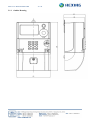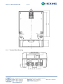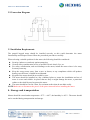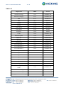
1
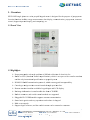
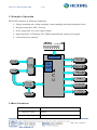
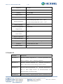
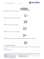
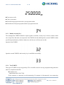
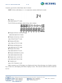
User Manual Single Phase Energy Meter HXE12-KP Hexing Electrical Co., Ltd. www.hxgroup.cn [2013.3] Meter User Manual-HXE12-KP 2 / 30 Introduction Range of validity The present user manual applies to the meter specified on the title page. Purpose The user manual contains all the information required for application of the meters for the intended purpose. This includes: z Provision of knowledge concerning characteristics, construction and function of the meter z Information about possible dangers, their consequences and measures to prevent any danger z Details concerning the performance of all work throughout the service life of the meter Target group The contents of this user manual are intended for technically qualified personnel of energy supply companies responsible for the meter planning, installation, operation and maintenance of the meter. Hexing Electrical reserves the right of final interpretation Meter User Manual-HXE12-KP 3 / 30 TABLE OF CONTENTS INTRODUCTION .................................................................................................................................................... 2 1. 2. OVERVIEW ..................................................................................................................................................... 5 1.1 FRONT VIEW ......................................................................................................................................................... 5 1.2 HIGHLIGHTS .......................................................................................................................................................... 5 1.3 PRINCIPLE OF OPERATION ..................................................................................................................................... 6 1.4 BASIC PARAMETERS .............................................................................................................................................. 6 1.5 STANDARDS .......................................................................................................................................................... 7 MAIN FUNCTIONS ......................................................................................................................................... 8 2.1 MEASUREMENT ..................................................................................................................................................... 8 2.1.1 Energy .............................................................................................................................................................. 8 2.1.2 Instantaneous Values ........................................................................................................................................ 8 2.1.3 Billing Data ...................................................................................................................................................... 9 2.2 LCD DISPLAY ....................................................................................................................................................... 9 2.2.1 Physical Characteristics .................................................................................................................................. 9 2.2.2 LCD Full Screen Display ............................................................................................................................... 10 2.2.3 LCD Display Items ......................................................................................................................................... 10 2.2.4 LCD Display Modes ....................................................................................................................................... 10 2.2.5 Status Indicator .............................................................................................................................................. 11 2.3 COMMUNICATION INTERFACES ............................................................................................................................ 11 2.3.1 Optical Communication ................................................................................................................................. 12 2.3.2 PLCCommunication ....................................................................................................................................... 12 2.3.3 GPRS Communication(optional with PLC) ................................................................................................... 12 2.4 KEYPAD .............................................................................................................................................................. 13 2.5 STS ..................................................................................................................................................................... 13 2.5.1 Recharge ........................................................................................................................................................ 13 2.5.2 Management TOKEN ..................................................................................................................................... 14 2.5.3 Modify Security Key ....................................................................................................................................... 15 2.5.4 Test TOKEN ................................................................................................................................................... 15 2.6 SHORT CUT KEYS ................................................................................................................................................ 17 2.7 LOW CREDIT ALARM .......................................................................................................................................... 18 2.8 EMERGENCY CREDIT ........................................................................................................................................... 18 2.9 FRIENDLY MODE ................................................................................................................................................. 20 2.10 SMS RECHARGE ................................................................................................................................................. 20 2.10.1 Input TOKEN number ................................................................................................................................ 20 2.10.2 Input Shortcut Key ..................................................................................................................................... 20 2.10.3 SMS Alarm ................................................................................................................................................. 21 2.10.4 Mobile Phone Number Binding ................................................................................................................. 21 2.11 LOAD CONTROL .................................................................................................................................................. 21 2.12 EVENT RECORDS ................................................................................................................................................. 21 2.12.1 Event Type 1 ............................................................................................................................................... 21 2.12.2 Event Type 2 ............................................................................................................................................... 22 2.12.3 Event Type 3 ............................................................................................................................................... 22 Meter User Manual-HXE12-KP 3. 4 / 30 2.12.4 Event Type 4 ............................................................................................................................................... 22 2.12.5 Event Type 5 ............................................................................................................................................... 22 2.12.6 Event Type 6 ............................................................................................................................................... 22 2.13 LOAD PROFILE .................................................................................................................................................... 22 2.14 DAYLIGHT SAVING TIME ..................................................................................................................................... 23 2.15 CONTACTOR ........................................................................................................................................................ 23 2.15.1 Physical Characteristics ............................................................................................................................ 23 2.15.2 Control Logic ............................................................................................................................................. 23 2.15.3 Reason of Operation .................................................................................................................................. 23 2.16 RTC .................................................................................................................................................................... 24 2.17 BATTERY ............................................................................................................................................................. 24 DIMENSIONS AND INSTALLATION .......................................................................................................... 24 3.1 DIMENSIONS ....................................................................................................................................................... 24 3.1.1 Outline Drawing ............................................................................................................................................ 25 3.1.2 Terminal Block Drawing ................................................................................................................................ 26 4. 3.2 CONNECTION DIAGRAM ...................................................................................................................................... 27 3.3 INSTALLATION REQUIREMENTS ........................................................................................................................... 27 STORAGE AND TRANSPORTATION .......................................................................................................... 27 ANNEX A ............................................................................................................................................................... 28 Meter User Manual-HXE M E12-KP 5 / 30 1. Overvview HXE12-KP P single phaase two wiree prepaid keypad k meteer is designeed for the ppurpose of prepayment p t. Its main funnctions incllude energyy measuremeent, data display, comm munication, prepaymen nt, contactor control, keyypad input and a inquiry,, anti-tampeering, etc. 1.1 Front View 1.2 Highliights ¾ Prrepayment mode m solvess the probleem of difficu ult collectioon of electricity fee. ¾ Baased on STS (Standardd Transfer Specificatio S on), which is an open ssecure transfer standardd annd the only internationaal specificattion on prep paid system m. ¾ DLMS/COSE EMCommuunication prootocol, whicch ensures good g interopperability. ¾ Cllosed type design d avoidds external attack throu ugh open innterface. ¾ Human machhine interfacce availablee: keypad inp put and LCD display. ¾ Reecharge info formation is transferredd in the form m of TOKEN N. ¾ Buuilt-in contaactor, and varied v controol methods are supportted. ¾ Plluggable PL LC/GPRS module m suppports remotee communiccation. ¾ Soome basic queries q and easy operattion can be done d via keeypad. ¾ Riich event reecords. ¾ Suupport logoff of meter, and the creedit in meterr can be retuurned to cusstomer. Meter User Manual-HXE12-KP 6 / 30 1.3 Principle of Operation HXE12-KP comprises of following components: ¾ Energy measuring unit: voltage sampling, current sampling, measuring integrated circuit; ¾ Data processing unit: MCU, memory; ¾ Power supply unit: AC power supply, battery; ¾ Input/output unit: LCD display, PLC/GPRS communication, optical port, keypad; ¾ Load control unit: contactor. 1.4 Basic Parameters Parameter Characteristics Reference voltage 220VAC Working voltage 70%Un~120%Un Meter User Manual-HXE12-KP 7 / 30 Frequency Current (50±5)Hz 5(60)A Accuracy Cl 1.0 for kWh Starting current 4‰Ib impulse constant Active: 1600 imp/kWh Normal working temperature: -25℃~+60℃ Working temperature Extreme working temperature: -40℃~+70℃ Relative humidity Power consumption in ≤95% ≤1.5W, 10VA voltage circuit Power consumption in ≤1VA current circuit Degrees of protection IP54 Fast transient burst 4kV Electrostatic discharges Insulation Impulse voltage Contact discharge8kV, air discharge 15kV 1 minute under 4kV, 50Hz 8 kV 1.5 Standards Standards Descriptions IEC62052-11 Electricity metering equipment (a.c.) – General requirements, tests and test conditions – Part 11: Metering equipment IEC62053-21 Electricity metering equipment (a.c.) - Particular requirements Part 21: Static meters for active energy (classes 1 and 2) IEC62053-31 Electricity Metering Equipment (a.c.) - Particular Requirements Part 31: Pulse Output Devices for Electromechanical and Electronic Meters (Two Wires Only) IEC62055-41 Electricity metering - Payment systems - Part 41: Standard transfer Meter User Manual-HXE12-KP 8 / 30 specification (STS) - Application layer protocol for one-way token carrier systems IEC62055-51 Electricity metering - Payment systems - Part 51: Standard transfer specification (STS) - Physical layer protocol for one-way numeric and magnetic card token carriers IEC62056-61 Electricity metering - Data exchange for meter reading, tariff and load control - Part 61: Object identification system (OBIS) IEC62056-62 Electricity metering - Data exchange for meter reading, tariff and load control - Part 62:Interface classes IEC62056-46 Electricity metering - Data exchange for meter reading, tariff and load control - Part 46: Data link layer using HDLC protocol IEC62056-53 Electricity metering - Data exchange for meter reading, tariff and load control - Part 53: COSEM application layer IEC62056-47 Electricity metering – Data exchange for meter reading, tariff and load control – Part 47:COSEM transport layer for IP networks 2. Main Functions 2.1 Measurement 2.1.1 z Energy The meter measures both forward and reverse active energy in the range of 000000.00~999999.99kWh. z Measurement mode: Forward= forward + reverse Reverse= reverse 2.1.2 Instantaneous Values z Active power z Voltage z Current z Power factor z Frequency Meter User Manual-HXE12-KP 2.1.3 z 9 / 30 Billing Data Monthly frozen energy: last 12 months data of monthly frozen occurrence time, total active energy,total reverse active energy. z Daily frozen energy: last 62 days data of daily frozen occurrence time, total active energy, total reverse active energy. z Monthly frozen credit: last 12 months data of monthly frozen occurrence time, remaining credit. z Daily frozen credit: last 62 days data of daily frozen occurrence time, remaining credit. Monthly frozen time is configurable in the format of XX(day):XX(hour) from 1st to 28th of every month. The default setting is 1st day 00 hour. Daily frozen time is configurable in the format of XX(hour):XX(minute). The default setting is 00:00. 2.2 LCD Display 2.2.1 Physical Characteristics z Visual size of LCD: 67.5mm*21mm; z Size of digit: 4.3mm*8.4mm; z z Working temperature of LCD: -30℃~+80℃; z High-contrast; z Wide viewing angle; z Anti-ultraviolet. Meter User Manual-HXE12-KP 2.2.2 LCD Full Screen Display 2.2.3 LCD Display Items 10 / 30 Display item Description Data display area OBIS code display area Unit display area Communication Reverse indication Low battery Contactor connected Contactor disconnected Recharge successful Recharge failed GPRS signal (S1~S8) 2.2.4 Event status indicator LCD Display Modes There are five types of LCD display modes: automatic scrolling display, push button display, keypad display, power off display, and meter abnormal display. z Automatic scrolling display Meter display mode is default as automatic scrolling display when power on. After meter operates for a certain period, which is automatic scrolling display interval default as 3s, Meter User Manual-HXE12-KP 11 / 30 LCD display will switch automatically to next page in sequential order circularly. Maximum 32 display pages can be configured, for details please refer to Annex A. z Push button display Once press the button in the front, automatic scrolling display/power off display will switch to push button display. LCD display switches to next page in sequential order circularly at each button-push. When there is no button-push within 30s, push button display will switch back to automatic scrolling display/power off display. Maximum 32 display pages can be configured, for details please refer to Annex A. z Keypad display When press the numbers in the keypad, the meter will enter keypad display mode and display relevant numbers in LCD. If there is no keypad operation after 20s, the meter goes back to automatic scrolling display mode(when there is power in the grid) or power-off display mode(when there is no power in the grid). When pressing effective shortcut key or TOKEN and press ENTER key, the meter will display relevant indicating message. After 10s it will go back to automatic scrolling display mode(when there is power in the grid) or power-off display mode(when there is no power in the grid). z Power off display Meter only displays credit of meter during power off. z Meter abnormal display Once fault or damage of meter memory is detected, automatic scrolling display will stop and LCD will be fixed to display abnormal code “Error”. 2.2.5 Status Indicator z When meter cover is open, z When terminal cover is open, z When meter is overloaded, z When meter cover open and terminal cover detection function is disabled, S2 indicates; S3 indicates; S4 indicates; S5 indicates; 2.3 Communication Interfaces Meter has one optical communication port, and one PLC/GPRS communication port(only one communication module between PLC and GPRS can be chosen for one meter). The two communication interfaces are independent from each other, thus, failure of one communication interface will not affect the other. Meter User Manual-HXE12-KP 2.3.1 z 12 / 30 Optical Communication It is in compliance with IEC 62056-21 standard: Electricity metering - Data exchange for meter reading, tariff and load control - Part 21: Direct local data exchange. z It is in compliance with DLMS standard (E mode). z Initial baud rate is 300bps, 7 data bits and 1 parity bit; after successful handshake, baud rate is 9600bps, 8 data bits and 1 parity bit. z Via optical communication user can read data from meter and do configuration through PC software or HHU. 2.3.2 PLCCommunication z Baud rate is 4800bps, 8 data digits and without check digit. z It is in compliance with DLMS standard (direct HDLC mode). z Meter reading and configuration can be realized through DCU via PLC communication in AMI network. z 2.3.3 Pluggable PLC communication module. GPRS Communication(optional with PLC) z Baud rate is 4800bps, 8 data digits and 1 parity digit. z It is in compliance with DLMS standard (COSEM-on-IP mode). The master station could read meter data and configure meter. z Meter reading and configuration can be realized through DCU via GPRS communication in AMI network. z GPRS and GSM communication methods. z Pluggable GPRS communication module. z GPRS signal strength indicator: Meter User Manual-HXE12-KP 13 / 30 ¾ : signal strength<9, means there is no signal ¾ : 9<= signal strength<14, means signal is weak ¾ : 14<= signal strength <19, means signal is normal ¾ : 19<= signal strength <23, means signal is good ¾ : 23<= signal strength, means signal is very good 2.4 Keypad There are totally 12 keys in this keypad. 0~9 are number keys, “ ” is clear key, “ ” is ENTER key. 2.5 STS 2.5.1 Recharge zCustomer goes to the vending station to purchase electricity and gets a customer card for the first purchase. z Customer enters 20-digit TOKEN via keypad. If the input is wrong, it could be modified by after confirmation. zWhen the recharge is successful, meter displays . Push Meter User Manual-HXE12-KP 14 / 30 zWhen TOKEN is wrong, meter displays zWhen TOKEN has been used, meter displays zWhen TOKEN expires, meter displays zWhen security key expires, meter displays zWhen charging amount exceeds the accumulated charging amount limit, meter displays 2.5.2 Management TOKEN STA encryption is adopted for this type of TOKEN. They can only be used for one specific meter at one time. z Set maximum power Meter User Manual-HXE12-KP 15 / 30 zClear meter credit z Clear event status z Switch from prepayment mode to post-payment mode z Switch mode from post payment mode to prepayment mode 2.5.3 Modify Security Key Two management TOKEN should be input together to modify security key. It doesn’t matter which one is input first. But after user inputs the first TOKEN, he/she shall input the second TOKEN within specified period(2min by default). Otherwise, the first one will become invalid. Input the first TOKEN: Input the second TOKEN, and security key is modified successfully. 2.5.4 Test TOKEN This type of TOKEN is not encrypted by STA. It could be used to test any prepayment keypad meter which is compliant with STS. z Contactor test 0000-0000-0001-5099-7584 If the contactor is connected, test disconnecting. If contactor is disconnected, test connecting. Meter User Manual-HXE12-KP 16 / 30 Contactor goes back to initial status after 2 minutes. NOTE: If the credit balance is <=0, connecting contactor shall not be tested. z LCD test 0000-0000-0001-6777-4880 Test LCD full screen display, check if any code is absent. z Display total active forward energy 0000-0000-0002-0132-8896 z Display security key version 1844-6744-0738-4377-2416 z Display tariff index 3689-3488-1475-5332-2496 z Display maximum power 0000-0000-0012-0797-4400 z Display meter status 0000-0000-0022-8172-8512 z Display instantaneous power 0000-0000-0044-2920-8064 z Display meter version No. 0000-0000-0087-2419-5840 z Complete test 5649-3153-7254-5031-3471 Make contactor test, LCD display test, display total active forward energy test, display security key version test, and display tariff index display in turn. The interval between each test shall be 8s~10s. Meter User Manual-HXE12-KP 17 / 30 2.6 Short cut Keys The meter provides a serial of shortcut code for customer to get meter information and make relevant operation thru the keypad: Short code Function Short code Function 800 Total active forward energy 801 Credit balance 802 Date 803 Time 804 Meter serial number 805 SGC number 806 Contactor operation reason 807 Meter status 808 Total instantaneous power 809 Tariff index 810 Overdraft limit 811 Emergency credit 812 Cancel audible alarm 813 Total active energy of yesterday 814 Total active energy of current 815 Last recharge date month 816 Last recharge time 817 Last recharge amount 818 Return logoff TOKEN 819 times of Power off 820 Total active energy of last1 month 821 Total active energy of last2 month 822 Total active energy of last3 month 823 Total active energy of last4 month 824 Total active energy of last5 month 825 Total active energy of last6 month 830 TOKEN number of last 1 831 TOKEN code of last 2 recharge number of last 3 833 TOKEN code of last 4 recharge number of last 5 835 TOKEN code of last 6 recharge number of last 7 837 TOKEN code of last 8 recharge number of last 9 839 TOKEN code of last 10 recharge recharge 832 TOKEN recharge 834 TOKEN recharge 836 TOKEN recharge 838 TOKEN recharge 865 meter is in normal mode Meter User Manual-HXE12-KP 18 / 30 2.7 Low Credit Alarm In order to remind the user to recharge in time and to avoid inconvenience of power disconnection, meter provides the function of low credit alarm, including visual alarm and audible alarm. Visual alarm: z When there is enough remaining credit, LED is green. z When remaining credit is less than low credit alarm level 1, LED is red. z When remaining credit is less than low credit alarm level 2, LED is red and flashes. Audible alarm: When remaining credit is less than low credit alarm level 3, buzzer is on. Customer can turn off the buzzer through manual token insertion. In consideration of not disturbing customer during rest time, audible alarm turns off automatically during 20:00-08:00. z Cancel audible alarm z no need to cancel audible alarm now 2.8 Emergency Credit Contactor disconnects automatically and there is no power supply when remaining credit reaches zero. However, in case that customer needs power supply and cannot go to purchase power immediately, meter provides the function of emergency credit. Customer can use short code 811 to get emergency credit and restore the power. Under the mode of emergency credit, meter calculates the remaining credit as a minus value. When Meter User Manual-HXE12-KP 19 / 30 remaining credit plus emergency credit reaches zero, contactor disconnects again. Function of emergency credit can only be used once before next recharge. The emergency credit will be deducted automatically during next recharge. z Emergency credit z Emergency credit has been used: z No need to use emergency credit now: z The meter is still lack of credit after emergency credit: z Emergency credit could not be used because the account has been closed. Meter User Manual-HXE12-KP 20 / 30 2.9 Friendly Mode Meter provides two modes of power interruption: normal power interruption and friendly mode. Under the mode of normal power interruption, contactor disconnects when remaining credit reaches zero. However, under friendly mode, in order to ensure consumer’s power consumption, contactor doesn’t disconnect during certain periods, i.e. overnights, at weekends or holidays, even if remaining credit reaches zero. Certain periods are configurable. 2.10 SMS Recharge 2.10.1 Input TOKEN number 2.10.1.1 Input Format P+20-digit TOEKN number, such as 11223344556677889900. 2.10.1.2 Output Format z Charging code successful Yüklənmişdirxxxxx.xx Manat, Balansxxxxx.xx Manat z TOKEN code failed Charging amount Meter credit balance Etibarsız şifrə 2.10.1.3 SMS Charging z The customer gets 20 digits TOKEN from the utility. z Edit SMS in mobile phone, the format is P+ 20-digit TOKEN, then send the SMS to the SIM card number of corresponding meter. z Meter will reply recharging SMS to customer’s mobile phone. 2.10.2 Input Shortcut Key 2.10.2.1 Input Format Q+shortcut key, such as input Q800 to check total active energy. 2.10.2.2 Output Format ztotal active energy Cəmi aktiv enerji xxxxxx.xxkVts. ztotal active energy of last 1~6 month Əvvəlki 1/2/3/4/5/6 ayın cəmi aktiv enerjisixxxxxx.xxkVts. Meter User Manual-HXE12-KP 21 / 30 zmeter credit balance Balansdakı qalıq xxxxxx.xx Manat. zShortcut Key failed Yanlış şifrə. 2.10.3 SMS Alarm 2.10.3.1 Credit Alarm When the meter’s credit balance is less than 1, the meter will initially send one SMS to user’s mobile phone to remind him to recharge in time. Balansın Azalması, xxxxxx.xxManat qalmışdır Meter credit balance 2.10.4 Mobile Phone Number Binding zInput format: B+ meter serial number +*mobile phone number that need binding zbinding failed: Mobil qeydiyyat alınmadı. zbinding successful: Mobil qeydiyyat uğurlu oldu. 2.11 Load Control z When active power is larger than threshold A and for a consecutive period which exceeds delay time B, contactor disconnects. z Then, after delay time C, contactor reconnects and meter starts over the process of overload detection. z If there are overload events for consecutive 5 times, times of overload events is reset to zero and contactor reconnects after delay time D. Then, meter starts over the process of overload detection. z If there is no overload event for consecutive time E, times of overload events is reset to zero. NOTE: during the load control process, if there is any power on and power off event, setting of max. power, or clearing events, the load control will go back to initial status and restart. 2.12 Event Records 2.12.1 Event Type 1 Meter records total occurrence times of events, total duration, start time and end time of last 10 events. Meter User Manual-HXE12-KP power off meter cover open terminal cover open over-voltage under-voltage 22 / 30 2.12.2 Event Type 2 Meter records total occurrence times of events, recharge time, recharge amount and recharge TOKEN of last 10 events. Recharge event 2.12.3 Event Type 3 Meter records total occurrence times of events, occurrence time and reason of last 10 events. contactor disconnected contactor reconnected 2.12.4 Event Type 4 Meter records total occurrence times of events, time before synchronization and time after synchronization of last 10 events. time synchronization 2.12.5 Event Type 5 Meter records total occurrence times of events and occurring time of last 10 events. overload 2.12.6 Event Type 6 Meter records total occurrence times of events, occurring time of last 10 events, subclass of management TOKEN, and management TOKEN. 2.13 time synchronization Load Profile z 8 channels zThe beginning address and storage space is set in the factory. It can’t be changed after leaving factory. Meter User Manual-HXE12-KP 23 / 30 zthe capture period and capture objects of each channel is configurable. zmax. 10 capture objects can be selected for each channel. And for easy reading purpose, the first capture object shall be fixed as time. zcapture objects: time, forward active energy, reverse active energy, voltage, current, active power, power factor, frequency, meter credit balance. zstorage space: 4M bytes ForFlash. 2.14 Daylight Saving Time zmax. 20 years’ DST setting is supported; zafter entering DST, meter’s time is 1 hour ahead, vice versa. 2.15 Contactor 2.15.1 Physical Characteristics z5,000 operations under rated current condition; z10,000 operations under no-load conditions. NOTE: In order to make sure reliable contactor operation and to avoid meter reset due to contactor operation, it is only allowed to operate the contactor when the voltage of power grid is higher than the threshold of contactor operation voltage(50%Un by default). 2.15.2 Control Logic zPrepaid control at local; zRemote contactor control; zPriority: Remote>local. Once the meter receives remote command of disconnection, contactor must disconnect, even though the meter still has credit; once the meter receives remote command of connection, contactor must connect, even though the meter doesn’t have credit. 2.15.3 Reason of Operation z 00: Normal status z01: Credit reaches zero, emergency credit has not been used z02: Credit reaches zero, emergency credit has been used z03: Overload and contactor disconnect z04: STS test disconnection z05: Meter cover open and contactor disconnect z06: Terminal cover open and contactor disconnect Meter User Manual-HXE12-KP 24 / 30 z07: Remote disconnection of contactor z09: Overvoltage and contactor disconnect z0C: Under voltage and contactor disconnect z 0D: reverse current and contactor disconnect z10: STS test connection z20: Remote connection of contactor Note: If contactor disconnection is caused by meter cover open or terminal cover open, contactor will remain disconnected, even if meter cover and terminal cover are closed. Under this circumstance, the meter needs a TOKEN to clear the events to connect the contactor. 2.16 RTC z Calendar, time and leap year switch available; z MCU internal RTC module, with 32768Hz crystal as clock source; z Frequency correction to 32768 required; zAccuracy0.5 s/d under normal temperature. 2.17 Battery z Lithium battery, the capacity is 1200 mAh. zWhen power off, meter starts to use battery to maintain RTC, LCD display, button operation and event recording. zWhen low battery is detected, LCD displays . z Lifetime is from 3~5 years, if meter works only with battery constantly. zBattery is replaceable. User can only replace battery when the power is off. If battery must be replaced during power on, the user shall be extremely careful and not get shocked. zIt is highly recommended to replace battery within 1 minute when power on or synchronize RTC after battery replacement. 3. Dimensions and Installation 3.1 Dimensions Length×width×height=204mm×132mm×85mm Meter User Manual-HXE12-KP 3.1.1 Outline Drawing 25 / 30 Meter User Manual-HXE12-KP 3.1.2 Terminal Block Drawing 26 / 30 Meter User Manual-HXE12-KP 27 / 30 3.2 Connection Diagram 3.3 Installation Requirements The prepaid keypad meter should be installed correctly as this could determine the meter functionality and lifespan. Please follow the prescribed procedures carefully. When selecting a suitable position for the meter, the following should be considered: z Security (indoors or outdoors) against tampering. z General safety consideration in case of possible electric shock, fire, etc. z For safety consideration, and avoid damage to the meter, install the meter where is far away from any water tap. z Keep the energy meter away from a stove or heater, or any compliance which will produce heating exceeds meter’s limited heat withstand. z Keypad of the meter should be accessible by user. z The meter should be installed in a dry ventilated place to ensure the installation and use of meter is secure and reliable. At places that are dirty or might damage the meter, a protection cabinet or box shall be used to protect the meter. z The meter should be fixed in a firm, fire-resistant surface that do not shake easily. NOTE Make sure to disconnect the power of the power network before installing the meter. 4. Storage and transportation Meters should be stored under temperature -25℃~+60℃, the humidity is <85%. The meter should not be crashed during transportation and storage. Meter User Manual-HXE12-KP 28 / 30 Annex A Display item OBIS Format Total active energy 1.8.0 XXXXXX.XX Total active energy(-) 2.8.0 XXXXXX.XX Date 0.9.2 DD-MM-YY Time 0.9.1 hh:mm:ss Voltage 32.7.0 XXX.X Current 31.7.0 XXX.XXX Active power 21.7.0 XX.XXXX Power factor 33.7.0 X.XXX Frequency 14.7.0 XX.XX Credit c.51.0 XXXXXX.XX Maximum power 1.35.0 XX.XXXX Meter No. 12.1.0 NNNNNNNN SGC No. c.51.3 NNNNNN overdraft limit c.51.1 XXXXXX.XX Low credit alarm 1 c.51.6 XXXXXX.XX Low credit alarm 2 c.51.7 XXXXXX.XX Low credit alarm 3 c.51.8 XXXXXX.XX total active energy of last 1 month 98.1.1 XXXXXX.XX total active energy of last 2 month 98.1.2 XXXXXX.XX total active energy of last 3 month 98.1.3 XXXXXX.XX total active energy of last 4 month 98.1.4 XXXXXX.XX total active energy of last 5 month 98.1.5 XXXXXX.XX total active energy of last 6 month 98.1.6 XXXXXX.XX Total active energy of yesterday 98.2.1 XXXXXX.XX 1.9.0 XXXXXX.XX Date of last recharge 99.3.1 DD-MM-YY Time of last recharge 99.3.2 hh:mm:ss rechargingamount of last recharge 99.3.3 XXXXXX.XX Total active energy of current month Meter User Manual-HXE12-KP 29 / 30 Total times of power-off 99.4.1 NNNN Total recharging amount c.51.9 XXXXXX.XX NOTE: Information in this document is subject to change without notice. The information is accurate at the time of printing (March, 2013) © Hexing Electrical Meter User Manual-HXE12-KP 1 / 30 Hexing Electrical Add: Shangcheng Industrial Zone, 1418 Moganshan Road, Hangzhou, China TEL: +86-571-28020767/769 FAX: +86-571-28029263 www.hxgroup.cn [email protected]