1
Meilhaus Electronic Manual
ME-260(D), ME-300 4.2E
•
•
•
••••••••
••••••••
••••••••
••••••••
Multi I/O Board
for ISA Bus
•
•
•
•
•
•
•
•
•
•
•
•
•
•
•
•
•
•
•
•
•
•
•
•
•
•
•
•
•
•
•
•
•
•
•
•
Imprint
Manual for ME-260(D), ME-300
Revision 4.2E
Revised: 10. January 2000
Meilhaus Electronic GmbH
Fischerstraße 2
D-82178 Puchheim/Munich
Germany
http://www.meilhaus.com
© Copyright 2000 Meilhaus Electronic GmbH
All rights reserved. No part of this publication may be reproduced or distributed
in any form whether photocopied, printed, put on microfilm or be stored in any
electronic media without the expressed written consent of Meilhaus Electronic
GmbH.
Important note:
The information contained in this manual has been reviewed with great care and
is believed to be complete and accurate. Meilhaus Electronic assumes no responsibility for its use, any infringements of patents or other rights of third parties
which may result from use of this manual or the product. Meilhaus Electronic assumes no responsibility for any problems or damage which may result from errors
or omissions. Specifications and instructions are subject to change without notice.
IBM and IBM PC AT/XT are trademarks of the International Business Machines
(IBM) Corporation
Borland Delphi is a trademark of Borland International Inc.
Turbo/Borland C is a trademark of Borland International Inc.
Visual C++ and VisualBasic are trademarks of the Microsoft Corporation.
HP VEE is a trademark of Hewlett-Packard
ME-VEC is a trademark of Meilhaus Electronic GmbH
Other company names and product names found in the text of this manual are
also trademarks of the companies involved.
Manual ME-300, 260(D)
Rev. 4.2E
Table of Contents
1
2
3
Introduction . . . . . . . . . . . . . . . . . . . . . . . . . . . . . . . . . . . . . . . . . . . . 7
1.1 Package contents . . . . . . . . . . . . . . . . . . . . . . . . . . . . . . . . . . . . 7
1.2 Features . . . . . . . . . . . . . . . . . . . . . . . . . . . . . . . . . . . . . . . . . . . 8
1.3 System Requirements . . . . . . . . . . . . . . . . . . . . . . . . . . . . . . . 10
1.4 Important Note . . . . . . . . . . . . . . . . . . . . . . . . . . . . . . . . . . . . 10
1.5 Available Software . . . . . . . . . . . . . . . . . . . . . . . . . . . . . . . . . . 11
Installation. . . . . . . . . . . . . . . . . . . . . . . . . . . . . . . . . . . . . . . . . . . . . 13
2.1 Hardware Installation . . . . . . . . . . . . . . . . . . . . . . . . . . . . . . . 13
2.1.1 Locations of the Jumpers . . . . . . . . . . . . . . . . . . . . . . . . 13
2.1.2 Jumper settings . . . . . . . . . . . . . . . . . . . . . . . . . . . . . . . 14
2.1.2.1 Setting the Base Address . . . . . . . . . . . . . . . . . 14
2.1.2.2 Setting the Input Mode . . . . . . . . . . . . . . . . . . . 14
2.1.2.3 Setting the Interrupt Line . . . . . . . . . . . . . . . . . 15
2.1.2.4 Default Settings . . . . . . . . . . . . . . . . . . . . . . . . 15
2.2 Driver Installation . . . . . . . . . . . . . . . . . . . . . . . . . . . . . . . . . . 15
2.2.1 Initial Installation under Windows 95/98/NT . . . . . . . . . . 15
2.2.2 Updating the Board Driver . . . . . . . . . . . . . . . . . . . . . . . 17
2.2.3 Changing Board Settings . . . . . . . . . . . . . . . . . . . . . . . . 17
2.3 Uninstall . . . . . . . . . . . . . . . . . . . . . . . . . . . . . . . . . . . . . . . . . . 18
2.3.1 Uninstall a Single Board . . . . . . . . . . . . . . . . . . . . . . . . . 18
2.3.2 Uninstall the DriverSystem . . . . . . . . . . . . . . . . . . . . . . . 19
Hardware . . . . . . . . . . . . . . . . . . . . . . . . . . . . . . . . . . . . . . . . . . . . . . 21
3.1 Functional Block Diagram . . . . . . . . . . . . . . . . . . . . . . . . . . . 21
3.2 General Notes . . . . . . . . . . . . . . . . . . . . . . . . . . . . . . . . . . . . . 21
3.3 A/D Section . . . . . . . . . . . . . . . . . . . . . . . . . . . . . . . . . . . . . . . 22
3.3.1 A/D Channel Wiring . . . . . . . . . . . . . . . . . . . . . . . . . . . 23
3.3.1.1 Single ended Operation . . . . . . . . . . . . . . . . . . 23
3.3.1.2 Differential Operation . . . . . . . . . . . . . . . . . . . 24
3.3.2 External Trigger . . . . . . . . . . . . . . . . . . . . . . . . . . . . . . . 26
3.3.3 Prototype Area for Input Circuitries . . . . . . . . . . . . . . . . 26
3.3.4 Voltage Shape of the A/D Section . . . . . . . . . . . . . . . . . 27
3.4 D/A Section . . . . . . . . . . . . . . . . . . . . . . . . . . . . . . . . . . . . . . . 28
3.4.1 D/A Channel Wiring . . . . . . . . . . . . . . . . . . . . . . . . . . . 29
3.4.2 Voltage Shape of the D/A Section . . . . . . . . . . . . . . . . . 30
3.5 Digital I/O Section . . . . . . . . . . . . . . . . . . . . . . . . . . . . . . . . . . 31
3.6 Counter/Timer . . . . . . . . . . . . . . . . . . . . . . . . . . . . . . . . . . . . . 31
3.7 Registers . . . . . . . . . . . . . . . . . . . . . . . . . . . . . . . . . . . . . . . . . . 33
Meilhaus Electronic
Page 3
Table of Contents
Rev. 4.2E
4
5
Manual ME-300, 260(D)
3.8 Test Program . . . . . . . . . . . . . . . . . . . . . . . . . . . . . . . . . . . . . . 39
3.9 Balancing . . . . . . . . . . . . . . . . . . . . . . . . . . . . . . . . . . . . . . . . . 39
Programming. . . . . . . . . . . . . . . . . . . . . . . . . . . . . . . . . . . . . . . . . . . 41
4.1 High Level Language Programming . . . . . . . . . . . . . . . . . . . 41
4.1.1 Example Programs . . . . . . . . . . . . . . . . . . . . . . . . . . . . 41
4.2 HP VEE Programming
. . . . . . . . . . . . . . . . . . . . . . . . . . . . . 41
4.2.1 User Objects . . . . . . . . . . . . . . . . . . . . . . . . . . . . . . . . . 42
4.2.2 HP VEE Example Programs . . . . . . . . . . . . . . . . . . . . . . 42
4.2.3 The "ME Board" Menu . . . . . . . . . . . . . . . . . . . . . . . . . . 42
4.3 LabVIEW™ Programming . . . . . . . . . . . . . . . . . . . . . . . . . . . 43
4.3.1 Virtual Instruments . . . . . . . . . . . . . . . . . . . . . . . . . . . . 43
4.3.2 LabVIEW™ Example Programs . . . . . . . . . . . . . . . . . . . . 44
4.4 Programming the Registers . . . . . . . . . . . . . . . . . . . . . . . . . . 44
4.4.1 Initialisation . . . . . . . . . . . . . . . . . . . . . . . . . . . . . . . . . 44
4.4.2 A/D Conversion . . . . . . . . . . . . . . . . . . . . . . . . . . . . . . 45
4.4.2.1 Simple A/D Conversion . . . . . . . . . . . . . . . . . . 45
4.4.2.2 Counter Controlled A/D Conversion with Interrupt
46
4.4.2.3 External Trigger . . . . . . . . . . . . . . . . . . . . . . . . 49
4.4.3 D/A Conversion . . . . . . . . . . . . . . . . . . . . . . . . . . . . . . 49
4.4.3.1 Setting the D/A mode . . . . . . . . . . . . . . . . . . . 49
4.4.3.2 Setting the Analog Outputs . . . . . . . . . . . . . . . 50
4.4.4 Digital I/O . . . . . . . . . . . . . . . . . . . . . . . . . . . . . . . . . . 50
4.4.5 Board Identification . . . . . . . . . . . . . . . . . . . . . . . . . . . . 51
Function Reference . . . . . . . . . . . . . . . . . . . . . . . . . . . . . . . . . . . . . . 53
5.1 Functional Overview of the 32 Bit Driver . . . . . . . . . . . . . . . 53
5.2 Naming Conventions . . . . . . . . . . . . . . . . . . . . . . . . . . . . . . . 53
5.3 Description of the API Functions . . . . . . . . . . . . . . . . . . . . . . 55
5.3.1 General Functions . . . . . . . . . . . . . . . . . . . . . . . . . . . . . 55
5.3.2 Analog Input . . . . . . . . . . . . . . . . . . . . . . . . . . . . . . . . . 57
5.3.3 Analog Output . . . . . . . . . . . . . . . . . . . . . . . . . . . . . . . 63
5.3.4 Digital I/O . . . . . . . . . . . . . . . . . . . . . . . . . . . . . . . . . . 64
5.3.5 Error Handling . . . . . . . . . . . . . . . . . . . . . . . . . . . . . . . 69
Table of Contents
Page 4
Meilhaus Electronic
Manual ME-300, 260(D)
Rev. 4.2E
Appendix . . . . . . . . . . . . . . . . . . . . . . . . . . . . . . . . . . . . . . . . . . . . . . . . . 71
A
Specifications . . . . . . . . . . . . . . . . . . . . . . . . . . . . . . . . . . . . . . 71
B
Pinout . . . . . . . . . . . . . . . . . . . . . . . . . . . . . . . . . . . . . . . . . . . . 74
B1
Pinout (50pin D-Sub Female) . . . . . . . . . . . . . . . . . . . . . 74
C
Accessories . . . . . . . . . . . . . . . . . . . . . . . . . . . . . . . . . . . . . . . . 75
D
Technical Questions . . . . . . . . . . . . . . . . . . . . . . . . . . . . . . . . 76
D1
Hotline . . . . . . . . . . . . . . . . . . . . . . . . . . . . . . . . . . . . . 76
D2
Service address . . . . . . . . . . . . . . . . . . . . . . . . . . . . . . . . 76
D3
Driver Update . . . . . . . . . . . . . . . . . . . . . . . . . . . . . . . . 76
E
Index . . . . . . . . . . . . . . . . . . . . . . . . . . . . . . . . . . . . . . . . . . . . 77
Meilhaus Electronic
Page 5
Rev. 4.2E
Manual ME-300, 260(D)
Page 6
Meilhaus Electronic
Manual ME-300, 260(D)
1
Rev. 4.2E
Introduction
Valued customer:
Thank you for purchasing the ME-300 data acquisition board.
You have chosen an innovative high technology board that left
our premises in a fully functional and new condition.
Please take the time to examine the contents of the package for
any loss or damage that may have occurred during shipping. If
there are any contents missing or if an item is damaged, contact
Meilhaus Electronic immediately.
Before you install the board in your computer, read this manual
carefully, especially the chapter describing board installation. Pay
careful attention to the instructions on how to set the dip switches and jumpers on the board. This will save you having to
open your PC case again.
1.1
Package contents
We take great care to make sure that the package is complete in
every way when it is shipped. We do ask, that you take the time
to examine the contents of the box. Your ME-260D, ME-300 pakkage consists of:
• PC board ME-260, ME-260D or ME-300
• This manual
• ME-300 driver system for Windows95/98/NT on CD-ROM or
disk
• 50pin D-sub male connector
Meilhaus Electronic
Page 7
Introduction
Rev. 4.2E
1.2
Manual ME-300, 260(D)
Features
Model Overview
Bus
A/D section
D/A section
Digital
I/O
ME-260
ISA
16 bit
12 bit/
200 kHz
16 s. e./8 diff.
channels
–
–
ME-260D
ISA
16 bit
12 bit/
200 kHz
16 s. e./8 diff.
channels
–
24
ME-300
ISA
16 bit
12 bit/
200 kHz
16 s. e./8 diff.
channels
12 bit/
100 kHz
4 independant channels
24
Model
Table 1: Model overview ME-300 series
The ME-300 with its variations of ME-260 and ME-260D are high
technology PC boards for use in ISA bus systems. The boards can
be run in PCs with ISA-16 bit slots. The 3 versions of the board
differ in which components are placed on the board. The circuit
board itself is the same for all versions.
The ME-300 is the fully equipped version with A/D, D/A conversion and 24 TTL digital input/output lines. The ME-260D does not
have the D/A converter while the ME-260 does not have the D/A
converter or the digital input/output lines. The connector interface is compatible for all versions. The pins which would have
the D/A or digital signals on the ME-300 are not connected on
the ME-260, ME-260D connectors. Only CMOS components are
used on the boards so the boards use less current. A compact design with FPGA control and a 4 layer circuit design allow the
boards format to be smaller and easier to handle.
Introduction
Page 8
Meilhaus Electronic
Manual ME-300, 260(D)
Rev. 4.2E
The A/D section of the ME-260/260D/300 is electrically isolated
from the rest of the board and from the AT system bus. A 3 W
DC/DC converter is used to run the A/D section. The board has
16 single ended or 8 differential analog inputs which can be set
by jumpers. The 12 bit A/D converter on the board (MAX176) can
reach a total sampling rate of up to 200 kHz. All modes of operation for the A/D conversions (block, single, continuous, timer
controlled, triggered, or interrupt mode) are selected by the software.
All 3 board version have a 512 X 16 bit FIFO memory whose status bits are accessible. The status bits can be polled by software
and a "FIFO half full" condition can be used to initiate an interrupt. The user can choose between interrupt 2, 3, 5, 7, 10, 11, 12,
or 15 which is set by a jumper on the board. The channel/gain
list of the 3 different versions can contain up to 256 entries for
hardware scanning. The parameters channel number, gain,
uni/bi polar, and channel list end are entered into the channel list
as 8 bit entries.
The D/A section of the board (without electrical isolation) is run
by a 1 W DC/DC converter. The D/A converter is a quad 12 bit
component (AD664) and allows direct 16 bit access from the PC.
The reset function (after power up or software reset) sets all outputs to a logical "0". All registers (16 bit) of the D/A component
are user accessible.
The digital I/O section of the board (without electrical isolation)
is a BCT543 component which has three 8 bit ports (A, B, C)
which can be programmed as input or output. The ports configured as output can also be read in if required.
The counter/timer section of the board is available on all 3 versions. The 8253 component is used which has three 16 bit counters. Counter 1 is cascaded with counter 0. The clock input to
counter 1 has an input frequency of 1.5 MHz. The output of
counter 0 starts a conversion based on the channel list (for every
pulse from counter 0 the channel list is processed which controls
the processing of one channel list to the next). Counter 2 is supplied with an input frequency of 3 MHz and controls the processing time between 2 channel list entries.
Meilhaus Electronic
Page 9
Introduction
Rev. 4.2E
Manual ME-300, 260(D)
The software included with the boards allows fast integration of
the boards into user applications under Windows95/98/NT.
Drivers are available for HP VEE (Hewlett-Packard) and
LabVIEW™ (National Instruments) – both under Windows
95/98/NT. Drivers for DOS and Windows 3.1 are available on
request.
1.3
System Requirements
The ME-260, ME-260D, and ME-300 boards can be installed into
any IBM AT/386/486, Pentium or compatible computer. One free
ISA 16 bit bus slot is required.
1.4
Important Note
If you use a PC with PCI bus and a BIOS with plug&play functionality, you will have to reserve the interrupt channel of this board
for the ISA bus in the BIOS of your computer for all plug in
boards with interrupt function. Else the interrupt function is not
available. The BIOS menu can vary depending on the manufacturer - please consult the user manual of your motherboard.
Please note: On some newer computers the ISA bus frequency
may be more than the standard 8 MHz. In this case we can not
guarantee that the board will function properly. Consult the configuration in the setup of your PC to see if this is the case.
To avoid excess electrical "noise" the board should be installed
in an ISA slot as far away from the video board as possible.
Introduction
Page 10
Meilhaus Electronic
Manual ME-300, 260(D)
1.5
Rev. 4.2E
Available Software
Windows95/98/NT 4.0
ME-260/300 system driver under
Windows95/98/NT
Windows 3.x
(on request)
MS-DOS
(on request)
High level languages 32 Bit (included)
Visual C++ V 4.0 or higher
Delphi V 2.0 or higher
Visual Basic V 4.0 or higher
Graphical programming tools (optional)
ME-300 Driver System for HP VEE
V 3.2 or higher
ME-300 Driver System for LabVIEW™
V 4.0 or higher (optional)
Test and demo software
For the newest versions and latest software releases, please consult the README file on the driver disk(s) supplied.
Meilhaus Electronic
Page 11
Introduction
Rev. 4.2E
Introduction
Manual ME-300, 260(D)
Page 12
Meilhaus Electronic
Manual ME-300, 260(D)
Rev. 4.2E
2
Installation
2.1
Hardware Installation
2.1.1
Locations of the Jumpers
W 3: Differential or
single-ended
mode
•
•
•
•
•
•
•
•
•
•
•
•
•
•
•
•
•
•
•
•
•
•
•
•
•
•
•
•
•
•
•
•
•
•
•
•
•
•
•
ADR 5…12
IRQ 15 12 11 10 7 5 3 2
••••••••
••••••••
••••••••
••••••••
W2: Interrupt
W1: Base address
50pin D-Sub female
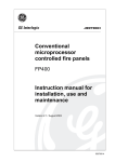
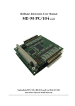
Diagram 1: Simplified illustration of the board
The address, interrupt line and single ended/differential modes
or operation are selected by setting jumpers on the ME-260(D)
and ME-300 board. The positions of these jumpers can be seen
in "Diagram 1: Simplified illustration of the board" on page 13
(the ME-260D layout is the same but several components are
missing). Detailed descriptions of the jumper settings are given
in the next section.
Meilhaus Electronic
Page 13
Installation
Rev. 4.2E
Manual ME-300, 260(D)
2.1.2
Jumper settings
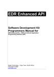
2.1.2.1
Setting the Base Address
The base address (BA) on the board is set by jumper W1. By
placing or removing the jumpers, the base address is set in binary
code. The ME-260/260D/300 requires 32 consecutive bytes of I/O
address space which starts with the base address. Make sure that
the jumper settings are not in conflict with other devices in the
computer.
A jumper that is "on" sets a logic "0" on the address line and a
jumper that is "off" sets a logic "1" on the address line. The base
address is determined by summing the jumpers which are "off".
The following example shows the default setting on the board
(700hex).
The address lines on the ME-260/260D/300 are fully decoded!
A0
A5
700Hex
A12
A15
0 0 0 0 0 0 0 0 1 1 1 0 0 0 0 0
Jumper
W1
Diagram 2: Setting the base address, e.g. standard setting
700Hex
2.1.2.2
Setting the Input Mode
The input mode can be set to either single ended or differential
mode. This is set by jumper W3.
differential
differential
single ended
single ended
Diagram 3: Setting the input mode
Installation
Page 14
Meilhaus Electronic
Manual ME-300, 260(D)
2.1.2.3
Rev. 4.2E
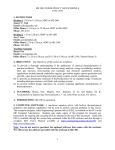
Setting the Interrupt Line
The desired interrupt line is selected by jumper W2. The IRQ lines 2, 3, 5, 7, 10, 11, 12, and 15 can be chosen. Make sure that
the interrupt line is not being used by any other devices.
The following picture shows, how the jumper has to be set to e.g.
choose IRQ line 12:
15
12
11
10
7
5
3
2
W2
Interrupt
Diagram 4: Setting the interrupt line, e.g. standard setting
IRQ 12
2.1.2.4
Default Settings
Function
Jumper/Switches
Setting
Base address
Jumper W1
700Hex
IRQ
Jumper W2
12
A/D operation
mode
Jumper W3
single ended
Table 2: Default settings of the ME-260/260D/300
2.2
Driver Installation
2.2.1
Initial Installation under Windows 95/98/NT
To install the driver under Windows 95/98 and Windows NT for
the first time, follow this procedure
☛ Insert the medium with the installation software.
☛ From the Windows start menu, choose Run… and click
Browse…. Enter the path and file name for the SETUP.EXE
Meilhaus Electronic
Page 15
Installation
Rev. 4.2E
Manual ME-300, 260(D)
file of the ME-260/300 installation. Confirm the selection and
follow the instructions of the setup program:
⇒ The installation programm will start.
☛ In the window "Install Options", choose "Install a new board"
and click OK.
☛ Note the dialogs and keep the settings of base address and interrupt channel ("2.1.2 Jumper settings" on page 14) ready for
input. Pay attention to the fact, that the input values have
to match the jumper settings on the board!
⇒ The following files will be installed:
❑ Windows95/98 only: Kernel driver ME300_32.VXD
into path <Windows-Verzeichnis>\SYSTEM
❑ WindowsNT only: Kernel driver ME300_32.SYS into
path <Windows-Verzeichnis>\SYSTEM32\DRIVERS
❑ API-DLL ME300_32.DLL under Windows95/98 into
path <Windows-Verzeichnis>\SYSTEM; under WindowsNT into path <Windows-Verzeichnis>\SYSTEM32
❑ Dialog DLL MEDLG32.DLL under Windows95/98 into
path <Windows-Verzeichnis>\SYSTEM; under WindowsNT into path <Windows-Verzeichnis>\SYSTEM32
⇒ Several files for high level language programming as well
as example- and test programs into the directory
<Meilhaus working directory>\ME-300 (see also README file on driver disk).
⇒ Registry entries will be made.
☛ Reboot your computer.
⇒ The system driver will be loaded automatically.
⇒ All the boards which were properly installed can be found
in the WindowsNT diagnostics under Resources. The important entries for the ME boards can be found under
"IRQ" and "I/O port".
Installation
Page 16
Meilhaus Electronic
Manual ME-300, 260(D)
Rev. 4.2E
Note:
The boards of the ME-300 series do not have plug&play functionality. Therefore they can not be found in the Windows95/98 device manager!
2.2.2
Updating the Board Driver
To update the board driver, the same procedure can be followed
for Windows95/98 and WindowsNT 4.0:
☛ Insert the medium with the installation software.
☛ From the Windows start menu, choose Run… and click
Browse…. Enter the path and file name for the SETUP.EXE
file of the ME-260/300 installation. Confirm the selection and
follow the instructions of the setup program:
⇒ The installation program will start.
☛ In the windows "Install Options" choose "Update driver and
language libraries" and click OK.
⇒ System drivers, API-DLL as well as libraries for programming languages, demo programs and test programs will all
be updated.
☛ Reboot your computer.
2.2.3
Changing Board Settings
Use the following procedure to change the settings of base
address and interrupt in the Windows registry. Note that the jumper settings on your board have to match thesettings in the registry. The same procedure can be followed for Windows95/98 and
WindowsNT 4.0:
☛ Insert the medium with the installation software.
☛ From the Windows start menu, choose Run… and click
Browse…. Enter the path and file name for the SETUP.EXE
file of the ME-260/300 installation. Confirm the selection and
follow the instructions of the setup program:
⇒ The installation program will start.
Meilhaus Electronic
Page 17
Installation
Rev. 4.2E
Manual ME-300, 260(D)
☛ In the window "Install Options" choose "Update settings of an
installed board" and click OK.
☛ Note the dialogs and keep the settings of base address and interrupt channel ("2.1.2 Jumper settings" on page 14) ready for
input. Pay attention to the fact, that the input values have
to match the jumper settings on the board!
☛ Reboot your computer
Under WindowsNT alternativly choose Settings ➜
System Control ➜ Devices from Start menu to unload and
reload the driver.
2.3
Uninstall
2.3.1
Uninstall a Single Board
The install and uninstall programs on your "ME-300 Driver
System" disk can be used to remove individual boards of the
ME-300 series from the Windows registry. The individual software components, e. g. system driver, API-DLL and the libraries
for programming languages, will not be removed in this case.
The same procedure can be followed for Windows95/98 and
WindowsNT 4.0:
☛ Insert the medium with the installation software.
☛ From the Windows start menu, choose Run… and click
Browse…. Enter the path and file name for the SETUP.EXE
file of the ME-260/300 installation. Confirm the selection and
follow the instructions of the setup program:
⇒ The installation program will start.
☛ In the window "Install Options" choose "Uninstall a single
board" and click OK.
☛ Choose the board you would like to remove from the Windows registry.
☛ Reboot your computer.
⇒ The board will be removed from the registry!
Installation
Page 18
Meilhaus Electronic
Manual ME-300, 260(D)
2.3.2
Rev. 4.2E
Uninstall the DriverSystem
Please note, that this procedure removes the entire ME-300 driver
system from your computer. All files will be removed, including
the system driver, the API-DLL (for all ME-300 series boards installed), the libraries for programming languages, the demo programs and the test programs, which are installed in the "ME-300"
subdirectory of "C:\MEILHAUS" (if the default install options were used). The same procedure can be followed for Windows
95/98 and WindowsNT 4.0:
☛ From the Windows start menu under the path Settings ➜
System Control ➜ Software in the property page
Install/Uninstall choose the "ME-300 Driver Uninstall" option
and click "OK".
⇒ The entire ME-300 driver system will be removed from
your computer!
Meilhaus Electronic
Page 19
Installation
Rev. 4.2E
Installation
Manual ME-300, 260(D)
Page 20
Meilhaus Electronic
Manual ME-300, 260(D)
Rev. 4.2E
3
Hardware
3.1
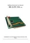
Functional Block Diagram
Functional block diagram for the ME-300 (the ME-260 does not
have the D/A section or digital I/O and the ME-260 does not have
the D/A section):
ME-300
Progr. gain
ADC
(MAX 176)
MUX
16
16 bit
8 bit
DAC
(AD664)
4
State
machine
16 bit
FIFO 16 bit
INT2, 3, 5, 7,
10…12, 15
(FIFO half full)
Timer
(71054)
Control,
address lines
8 bit
Digital I/O
(BCT 543)
24
50pin D-Sub female
Opto-isolation
Ext. trig.
Data
Bus interface logic
AT I/O interface
Diagram 5: Functional Block Diagram
3.2
General Notes
Important note: The external cable/connector should only be
connected or disconnected from the D-sub connector on the
board in a powered down condition (no voltage on any pins).
This is true for all A/D and all D/A channels.
The ME-260’s, ME-260D’s and ME-300’s D-Sub female connectors
have the same pinout, except that the unused pins (e. g. digital
I/Os for the ME-260 and D/A channels for the ME-260 and ME260D) are not connected. For connection details see "B1
Pinout (50pin D-Sub Female)" on page 74.
Meilhaus Electronic
Page 21
Hardware
Rev. 4.2E
3.3
Manual ME-300, 260(D)
A/D Section
The A/D section of the ME-260/260D/300 is electrically isolated
from the system bus and the rest of the board and is run by a 3 W
DC/DC converter. The ME-260/260D/300 has 16 single ended or
8 differential input channels. The input channels are individually
multiplexed to the programmable gain amplifier. The 12 bit A/D
converter on the board (type MAX176) allows a total sampling rate of up to 200 kHz. All modes of operation (block, single, continuous, timer controlled, external trigger or interrupt) can be set
by software. The operation is controlled by an FPGA component
type XILINX XC3030-70.
The channel/gain list of the ME-260/260D/300 can hold a maximum of 256 entries for hardware scan functions. The parameters
channel number, gain, uni/bipolar, and channel list end are 8 bit
entries in the channel list.
There are 2 types of pin compatible components available for the
ME-260/260D/300 programmable amplifier:
Type 1: PGA 203 (standard)
Type 2: PGA 202
Note: After installing a new amplifier on a board, balancing must
be done.
The board can reach its full total sampling rate when the gains in
the channel list are static (all the same).
The maximum total sampling rate will lower when dynamic gain
(the gain changes during the processing of the channel list) is
used. This results from the time required for the amplifier to
settle.
Hardware
Page 22
Meilhaus Electronic
Manual ME-300, 260(D)
Rev. 4.2E
PGA 203
PGA 202
1
0…10V
+/- 10V
1
0…10V
+/- 10V
2
0…5V
+/- 5V
10
0…1V
+/- 1V
4
0…2,5V
+/- 2,5V
100
0…0,1V
+/- 0,1V
8
0…1,25V
+/- 1,25V
1000
0…0,01V
+/- 0,01V
Table 3: Programmable gain
3.3.1
A/D Channel Wiring
Important note: The external cable/connector should only be
connected or disconnected from the D-sub connector on the
board in a powered down condition (no voltage on any pins).
This is true for all A/D and all D/A channels.
As a rule, all unused input lines should be connected to ground
to avoid cross talk between channels.
When handling the board and connecting the cables or connector block make sure that no static electrical charge is present. The
input multiplexers are protected to a maximum of 60 V. Any static charge or voltage peaks larger than 60 V could cause damage
on the board.
Wiring the analog inputs with your application is dependant on
whether they are configured as single ended or differential.
3.3.1.1
Single ended Operation
In single ended operation all analog inputs are referenced to analog ground. All negative lines on the sources must also be connected to analog ground (AGND, pin 2). The positive lines are
connected to the individual input channel lines.
When wiring it is important to make sure that all negative lines
are at the same voltage level to avoid short circuits between the
sources.
Meilhaus Electronic
Page 23
Hardware
Rev. 4.2E
Manual ME-300, 260(D)
Note: Shielded cable should be used.
Pin 41, channel 0
+
Pin 40, channell 1
Unused lines
.
.
.
Source 1
+
Source 2
-
-
Pin 02, AGND
Diagram 6: Wiring for single ended operation
3.3.1.2
Differential Operation
In differential mode, there are 8 analog inputs available. For
every channel, a positive and a negative input line are required.
Make sure that there is a reference to analog ground in differential operation as well. This is achieved by placing a resistor (approx. 10 kΩ) between the negative terminal of the source and
analog ground.
The positive inputs are from channels 0 to 7 and the negative inputs are from channels 8 to 15. See the table below:
Hardware
Page 24
Meilhaus Electronic
Manual ME-300, 260(D)
Rev. 4.2E
Positive Input
Pin No.
Negative Input
Pin No.
Channel 0
41
Channel 8
25
Channel 1
40
Channel 9
24
Channel 2
39
Channel 10
23
Channel 3
38
Channel 11
22
Channel 4
37
Channel 12
21
Channel5
36
Channel 13
20
Channel 6
35
Channel 14
19
Channel 7
34
Channel 15
18
Table 4: Positive and negative channels in differential mode
+
Source 1
Pin 41, channel 0
Pin 40, channel 1
Pin 25, channel 8
Pin 24, channel 9
R
Pin 2, AGND
…
Unused channels
R
+
Source 2
-
R≈10 kΩ
Diagram 7: Wiring for differential operation
Meilhaus Electronic
Page 25
Hardware
Rev. 4.2E
3.3.2
Manual ME-300, 260(D)
External Trigger
The processing of the channel list can also be started by an external trigger. The external trigger is an output and belongs to the
electrically isolated analog input section of the board. To create
an external trigger, pins 1 (DGND) and 3 (ext.trig) are connected
through a switch which has not been isolated from the computer
ground. Software controls whether a rising or falling edge causes
the triggering (the opening or closing of the switch).
Warning: Connecting an external TTL trigger signal on pin 3 and
pin 1 is possible but it removes the electrical isolation of the analog input section of the board. This can be corrected by using an
electrically isolated TTL signal if required.
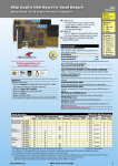
3.3.3
Prototype Area for Input Circuitries
For convenient setting of input circuitries a prototype area is provided on the board. Using this area, the unused input channels
in single ended mode can be connected to ground or the negative input channels 8…15 in differential mode can be easily connected to ground by a 10 kΩ resistor.
•
•
•
•
•
•
•
•
•
•
•
•
•
•
•
•
•
•
•
•
•
•
•
•
•
•
•
•
•
•
•
•
•
•
•
•
•
•
•
Prototype space for
input circuitries
Diagram 8: Prototype area, location
Hardware
Page 26
Meilhaus Electronic
Manual ME-300, 260(D)
Rev. 4.2E
ISO-SGND
A/D channel 8
A/D channel 9
A/D channel 10
A/D channel 11
A/D channel 12
A/D channel 13
A/D channel 14
A/D channel 15
W6
W5
ISO-SGND
A/D channel 0
A/D channel 1
A/D channel 2
A/D channel 3
A/D channel 4
A/D channel 5
A/D channel 6
A/D channel 7
ISO-SGND
Diagram 9: Prototype area, wiring
3.3.4
Voltage Shape of the A/D Section
Control word for the CONTROL1 register:
01hex, gain 1, unipolar:
[digits]
4095 (FFFHex)
4095
(FFFHex)
2047 (7FFHex)
2047
(7FFHex)
2048 (800Hex)
0
0
-10
0
5
10
U in [V]
Diagram 10: Digits over input voltage (unipolar)
Meilhaus Electronic
Page 27
Hardware
Rev. 4.2E
Manual ME-300, 260(D)
Control word for the CONTROL1 register:
01hex, gain 1, bipolar:
[digits]
4095 (FFFHex)
4095
(FFFHex)
2048 (800Hex)
2047
(7FFHex)
0
0
-10
0
10
U in [V]
Diagram 11: Digits over input voltage (bipolar)
The A/D converters output inverse non-linearized 12 bit values.
In this case the values must be linearized before the values are
processed.
3.4
Linearization syntax in Delphi:
Digits = Digits XOR $7FF
Linearization syntax in C:
Digits ^= 0X7FF
D/A Section
The ME-300 has a quad 12 bit D/A converter of the type AD664.
The D/A section is not electrically isolated and is run by a 1 W
DC/DC converter. The 16 bit values can be directly accessed from
the PC. The reset function (on power up or through a software
reset) sets all the outputs to 0 V. All registers (16 bit) of the D/A
converter are accessible from the PC. An analog voltage is first
read in, then loaded and then sent to the output.
The D/A outputs have a limited bandwidth due to the operational
amplifier. This means that the maximum frequency range of the
converter is available. Depending on the application, the user
should anticipate a limited bandwidth to avoid HF noise from interfering with the digital I/O lines.
Hardware
Page 28
Meilhaus Electronic
Manual ME-300, 260(D)
3.4.1
Rev. 4.2E
D/A Channel Wiring
The easiest way to do this is to use an R/C low pass filter with a
3 dB frequency that should be about 10 times larger than the maximum signal frequency.
Wiring example (ME-300 only!):
D/A channel A
Pin 8
R
C
Load
AGND DAW
Pin 4
Diagram 12: Wiring the D/A outputs
Meilhaus Electronic
Page 29
Hardware
Rev. 4.2E
3.4.2
Manual ME-300, 260(D)
Voltage Shape of the D/A Section
Control word for the CONTROL1 register:
01hex, gain 1, unipolar:
U in [V]
10
5
0
0
2047
(7FFHex)
4095 [digits]
(FFFHex)
Diagram 13: Output voltage over digits (unipolar)
Control word for the CONTROL1 register:
01hex, gain 1, bipolar:
U in [V]
+10 (+5)
0
2047
(7FFHex)
4095 [digits]
(FFFHex)
-10 (-5)
Diagram 14: Output voltage over digits (bipolar)
Hardware
Page 30
Meilhaus Electronic
Manual ME-300, 260(D)
3.5
Rev. 4.2E
Digital I/O Section
The digital I/O section on the ME-260D and ME-300 is realised
through the BCT543 component and is not electrically isolated
from the rest of the board. Each component has 3 digital I/O
ports which are individually programmable as input or output.
Ports programmed as output can also be read back. The maximum sink current (IOL→VCC, IOH→GND) is 50 mA per bit.
When setting the digital I/O lines and external trigger signal on
the ME-260D and ME-300, it is very important to maintain the TTL
voltage level standards and that the voltages are referenced to digital ground (pin 50).
3.6
Counter/Timer
The 8253 counter/timer chip serves to synchronise the sampling
of the analog inputs at a fixed frequency. There are three independent 16 bit counters.
The three counters have the following functions:
• counter 1 is cascaded with counter 0 on the ME-260/260D/
300. A frequency of 1.5 MHz is on the clock input of counter
1. The output of counter starts a conversion of the A/D channel list therefore for every pulse from counter 0 the channel
list is processed once (the time between the processing of one
channel list to the next is the SCAN-time).
• counter 2 has a frequency of 3 MHz on the clock input and
controls the processing time between 2 consecutive channel
list entries (the CHAN-time).
Meilhaus Electronic
Page 31
Hardware
Rev. 4.2E
Manual ME-300, 260(D)
in
Timer
Chip
out
scan
Counter 0
1,5 MHz Clock
Counter 1
chan
3,0 MHz Clock
Counter 2
channel
Diagram 15: Wiring of the ME-260/260D/300’s counters
ch2
ch1
ch0
ch2
ch1
ch0
scan
t
chan
Diagram 16: Conversion with channel list
If bit b2 of the CONTROL1 register (bit "period") is set to "1" then
counters 0 and 1 are ignored. The sampling rate is then only dependant on counter 2. The time between the last channel list entry to the first entry in the next channel list is still the CHAN-time.
The sampling rate fa is calculated as follows:
:
3 MHz
f a = -------------------------------------------------(counter 2 value) + 2
3 MHz
(counter 2 value) = ----------------- – 2
fa
Note: The SCAN time has to be at least CHAN-time x number of
channellist entries.
Hardware
Page 32
Meilhaus Electronic
Manual ME-300, 260(D)
3.7
Rev. 4.2E
Registers
The ME-260/260D/300 board requires 32 consecutive address locations in the PC. The base address (BA) is selected by a DIP
switch. The D/A registers for the ME-260 and ME-260D and the
digital I/O registers for the ME-260 are reserved. There are 8 bit
and 16 bit registers available. The following table can be used to
distinguish between (R = read, W = write):
Offset
BA+00H
8 Bit-Register
R
FID
contains identification information for the
board:
b7, b6 . . . reserved
b5 . . . . . . function group AI (A/D section)
b4 . . . . . . function group AO (D/A section)
b3 . . . . . . function group DIO (Digital
I/O)
b2… b0 . . PROM version
the PROM version identifies the board as
follows:
ME-300: 00111001=39Hex
ME-260: 00100001=21Hex
ME-260D: 00101001=29Hex
W
ADSTART
Software conversion is started by writing a
dummy value in this register
Table 5: Adress space of the ME-260/260D/300 (8 bit registers)
Meilhaus Electronic
Page 33
Hardware
Rev. 4.2E
Manual ME-300, 260(D)
Offset
BA+01H
8 Bit-Register
W
CONTROL1
b7 . . . . . . dout_c
1
output driver port C enable
b6 . . . . . . dout_b
1
output driver port B enable
b5 . . . . . . dout_a
1
output driver port A enable
b4 . . . . . . trig_pol
0
falling edge
1
rising edge
b3 . . . . . . reserved
b2 . . . . . . period
0
counter 0 and 1 are active ("3.6
Counter/Timer" on page 31)
1
counter 0 and 1 ignored. . If the
channel list has only 1 entry
the sampling frequency is calculated as follows:
3 MHz
f a = -------------------------------------------------(counter 2 value) + 2
3 MHz
(counter 2 value) = ----------------- – 2
fa
At the maximum sampling rate
counter 2 should be loaded
with 13.
b1, b0. . . . mode
0 0
stop A/D
0 1
start per Software
1 0
start per counter
1 1
ext. trigger
Table 5: Adress space of the ME-260/260D/300 (8 bit registers)
Hardware
Page 34
Meilhaus Electronic
Manual ME-300, 260(D)
Rev. 4.2E
Offset
BA+01H
BA+02H
8 Bit-Register
R
STATUS
b7…b4. . .
b3 . . . . . .
0
b2 . . . . . .
0
b1 . . . . . .
0
b0 . . . . . .
1
reserved
fifo_full
FIFO full
fifo_half
FIFO over half fulll
fifo_empty
FIFO empty
write_busy
write to channel list not ready
W
CONTROL2
b7 . . . . . .
1
reset A/D state machine
b6, b5 . . . interrupt source
0 0
no interrupt source
1 0
FIFO half full
0 1
external (Pin 3 of the 50pin DSub female connector)
1 1
A/D conversion ready
b4 . . . . . .
1
interrupt enabled
b3 . . . . . .
1
simultaneous D/A mode active
b2 . . . . . .
1
clear FIFO
b1 . . . . . .
1
reset channellist write counter
b0 . . . . . .
1
reset D/A converter
R
RESETINT
By reading a dummy value from the register, the interrupt control on the board is
reset.
Table 5: Adress space of the ME-260/260D/300 (8 bit registers)
Meilhaus Electronic
Page 35
Hardware
Rev. 4.2E
Manual ME-300, 260(D)
Offset
8 Bit-Register
BA+03H
W
KANALLISTE
b7 . . . . . .
0
channellist entry follows
1
last channellist entry
b6 . . . . . .
0
bipolar
1
unipolar
b5, b4. . . . gain
PGA 203
PGA 202
0 0
gain
1
1
0 1
gain
2
or
10
1 0
gain
4
or
100
1 1
gain
8
or
1000
b3…b0. . . channel
channel 0…15
BA+04H
R/W
TIMER0DATEN
Enter low byte then high byte (the register
must always be accessed twice!)
BA+05H
R/W
TIMER1DATEN
Enter low byte then high byte (the register
must always be accessed twice!)
BA+06H
R/W
TIMER2DATEN
Enter low byte then high byte (the register
must always be accessed twice!)
BA+07H
R/W
TIMERCONTROL
Important control words for the counter
component:
select counter 0: Hex 34
select counter 1: Hex 74
select counter 2: Hex B4
BA+08H
R/W
DIGITALA
Input/output data for port A
Table 5: Adress space of the ME-260/260D/300 (8 bit registers)
Hardware
Page 36
Meilhaus Electronic
Manual ME-300, 260(D)
Rev. 4.2E
Offset
8 Bit-Register
BA+09H
R/W
DIGITALB
Input/output data for port B
BA+0AH
R/W
DIGITALC
Input/output data for port C
Table 5: Adress space of the ME-260/260D/300 (8 bit registers)
Offset
BA+10H
BA+12H
16 Bit-Register
R/W
FIFO
b15…b12. channel number
b11…b0. . digits
Reserved
Table 6: Adress space of the ME-260/260D/300 (16 bit registers)
Meilhaus Electronic
Page 37
Hardware
Rev. 4.2E
Manual ME-300, 260(D)
Offset
BA+14H
16 Bit-Register
R/W
DACONTROL
Control word for D/A converter
b15
b11
b8
X
X
X
X
GA GB GC GD
b7
b4
MA MB MC MD X
X
X
b0
X
GA…GD: gain for D/A converter A, B, C
and D
MA…MD: mode for D/A converter A, B, C
and D (0 = unipolar, 1 = bipolar)
X:
reserved
results in the following D/A output ranges:
GA…
MA…
Digits
GD
MD
Ranges
0……4095
0
0
0…10 V
0 V +10 V
0
1
±5 V
-5 V +5 V
1
0
–
❍
❍
1
1
±10 V -10 V +10 V
❍ = not allowed
BA+16H
Reserved
BA+18H
R/W
DADATAA
Data for D/A converter A
BA+1AH
R/W
DADATAB
Data for D/A converter B
BA+1CH
R/W
DADATAC
Data for D/A converter C
BA+1EH
R/W
DADATAD
Data for D/A converter D
Table 6: Adress space of the ME-260/260D/300 (16 bit registers)
Hardware
Page 38
Meilhaus Electronic
Manual ME-300, 260(D)
3.8
Rev. 4.2E
Test Program
A test program is supplied with the boards. The test program
(ME300.EXE) is installed automatically into the directory
Meilhaus\ME-300\Test (Default) an can be started with a
double mouse click (on condition that system driver was properly installed).
3.9
Balancing
The board is delivered in a fully functional and balanced condition. If it should become necessary to balance the board (for example after use in a very "noisy" environment), please send the
board to the Meilhaus Electronic Service Department (see
page 76).
Meilhaus Electronic
Page 39
Hardware
Rev. 4.2E
Hardware
Manual ME-300, 260(D)
Page 40
Meilhaus Electronic
Manual ME-300, 260(D)
Rev. 4.2E
4
Programming
4.1
High Level Language Programming
The following high level languages are supported:
• Visual C++ (version 4.0 or higher). Please read the notes in
the respective README files
• Delphi (version 2.0 or higher). Please read the notes in the respective README files.
• Visual Basic (version 4.0 or later). Please read the notes in the
respective README files.
• for further high level languages see the respective README
files on your driver disk(s).
Note: The compilers and linkers require the correct paths to be
set to the corresponding files in the high level languages.
By linking the high level language specific MEDEFS.* files into
your project you can pass many macros and parameters in the
form of predefined constants (e. g. REGISTER_SET_A). As an alternative, you can pass the matching Hex value at any time.
4.1.1
Example Programs
We have provided simple demo programs with source code to
help understanding of the functions and how to incorporate them
into your project. These demo programs are installed automatically to appropriate subdirectories of C:Meilhaus\ (Default). If
required, parts of these programs can be easily copied into your
project by clipboard. Please read the notes in the respective
README files.
4.2
HP VEE Programming
The easiest way to install the HP VEE components for the
ME-260/300 is using the start file of your installation medium.
Meilhaus Electronic
Page 41
Programming
Rev. 4.2E
Manual ME-300, 260(D)
The ME-300, ME-260 and ME-260D are supported by HP VEE full
versions 3.2 or higher under Windows 95/98/NT. For installation
of HP VEE components and for further infos please note the PDFfile on the installation medium. For basics of HP VEE programming please use your HP VEE documentation and the
HP VEE online help index.
4.2.1
User Objects
For convenient use of the driver, predefined User Objects (UOs)
have been developed which internally call API functions. They
can be called by the additional menu item "ME Board" and be
included in the HP VEE development environment. They can be
placed and "wired" in your application the same as standard
HP VEE objects.
The UOs are self descriptive and based on the API functions documented in chapter "5 Function Reference" on page 53. Additionally there are some „Expanded User Objects“ for making
programming as easy as possible for you. A short description of
every UO you find under the item "Description" if you move the
cursor over the UO and push the right mouse button.
The UOs can be changed any time for user requirements and can
be saved as a user specific object.
4.2.2
HP VEE Example Programs
For demonstration purposes and for easier understanding, demo
programs using the important UOs have been written. They can
be called by the menu item "ME Board - Demos".
The HP VEE demo programs contain partial additions to the "normal" UOs and for differentiation from the "normal" UOs the prefix
"x…" in their file name is used.
4.2.3
The "ME Board" Menu
The installation program automatically expands the HP VEE
menu by the "ME Board" entry. It enables a convenient use of all
driver functions available in HP VEE. By the "ME Board" menu
Programming
Page 42
Meilhaus Electronic
Manual ME-300, 260(D)
Rev. 4.2E
you can call the driver and demo User Objects sorted by board
families.
Note:
The User Objects (UOs) installed, depend on the selected board
family at the beginning of your HP VEE driver installation. If you
call UOs under the "ME Board" menu which are not installed, an
error message occures:
File ’filename’ was not found.
Error number: 700
If necessary you can install the additional HP VEE components
any time (see installation medium).
4.3
LabVIEW™ Programming
LabVIEW™ components for the ME-300 are delivered optional on
(a) seperate disk(s) from Meilhaus Electronic. The ME-300,
ME-260D and ME-260 are supported by LabVIEW™ full versions
4.x or higher under Windows 95/98/NT. For installation of LabVIEW™ driver components and for further infos please note the
corresponding README-file on disk(s) delivered with the
LabVIEW™ driver. For basics of LabVIEW™ programming please
use your LabVIEW™ documentation and the LabVIEW™ online
help index.
4.3.1
Virtual Instruments
For convenient use of the driver, predefined "Virtual Instruments"
(VIs) have been developed which internally call API functions.
They can be called by the additional menu item "File - Open" and
be included in the LabVIEW™ development environment. They
can be placed and "wired" in your appli-cation the same as standard LabVIEW™ objects.
The VIs are self descriptive and based on the API functions documented in chapter "5 Function Reference" on page 53. Additionally there are some „Expanded Virtual Instruments“ for making
programming as easy as possible for you.
Meilhaus Electronic
Page 43
Programming
Rev. 4.2E
Manual ME-300, 260(D)
A short description of every VI you find in the VI "ME-300
Function Tree", which can be opened by the menu "File - Open".
Under "Description" you find a short description of every VI.
The VIs can be changed any time for user requirements and can
be saved as a user specific VI.
4.3.2
LabVIEW™ Example Programs
For demonstration purposes and for easier understanding, demo
programs using the important "Virtual Instruments" (VIs) have been written. They can be called by the menu item "File - Open".
4.4
Programming the Registers
Note: The boards can be programmed with high level programming languages using inport and outport commands (e.g. in
case you have already written software and would like to addapt
it). You can find information about port I/O command syntax in
the user manuals provided with the programming languages of
your choice. We recommend to use the driver software under
Windows95/98 or NT supplied with the ME boards.
The software delivered with the board contains examples of register programming. The constants used in the sample programs
are also shown in the appendix.
4.4.1
Initialisation
• All actions on the board are stopped: the CONTROL1 and
CONTROL2 resisters are set to 00hex.
• The interrupt handling on the board is reset by reading from
the RESETINT register.
• The D/A converter is reset: set bit 0 in the CONTROL2 register
and then reset.
• The state machine is reset: set bit 7 in the CONTROL2 register
and then reset.
• The channel list is reset: set bit 1 in the CONTROL2 register
and then reset.
Programming
Page 44
Meilhaus Electronic
Manual ME-300, 260(D)
Rev. 4.2E
4.4.2
A/D Conversion
4.4.2.1
Simple A/D Conversion
Conversion start by software (polling)
• Initialise the board ("4.4.1 Initialisation" on page 44)
• Write the channel list into the CHANNELLIST register even if
only one entry is required
The channel list has a maximum size of 256 entries. Make sure
that bit 7 in the last channel list entry is set to a logic "1".
Bit definitions in a channel list entry:
3…0
5, 4
channel (0…15)
gain
6
polarity (0=bipolar or 1=unipolar)
7
set to "1" in the last channel list entry
(It is possible to have a channel list with only one entry)
• Wait for the channel list to be loaded into the board: bit 0 in
the STATUS register must return to "0" (must be repeated after
each channel list entry)
• Write the control word for counter 2 (B4hex) in the TIMERCONTROL register
• Write the values for counter 2 (313) in the TIMER2DATA register. First the low byte and then the high byte are written (two
writes are always required). Counter 2 is also active when the
conversion is started by software (CHAN-time).
If a dynamic gain is used (different gains for different channel
list entries) the amplifier will require a short time to settle. In
this case timer 2 should be loaded with value of approx.
20…30.
Meilhaus Electronic
Page 45
Programming
Rev. 4.2E
Manual ME-300, 260(D)
• Mode programming: setting bits 1 and 2 in the CONTROL1 register:
Bit 1
Bit 0
Mode
0
0
Stops A/D conversion
0
1
Start via software
1
0
Start via counter
1
1
Start via ext. trigger
Table 7: Register CONTROL1
• Reset the FIFO: set bit 2 in the CONTROL2 register and then
reset.
• To start conversion, write a value into register ADSTART
• Wait for the conversion to be completed: check bit 1 in the
STATUS register until it is set to "1".
• The conversion result is available in the FIFO register (a
"word" access is required!). Bits 12…15 contain the converted
value from the channel.
Note: There is a 1ms delay every time the FIFO register is accessed.
4.4.2.2
Counter Controlled A/D Conversion with Interrupt
Conversion start controlled by the counter
• Initialise the board ("4.4.1 Initialisation" on page 44)
• Write the channel list into the CHANNELLIST register even if
only one entry is required
The channel list has a maximum size of 256 entries. Make sure
that bit 7 in the last channel list entry is set to a logic "1".
Bit definitions in a channel list entry:
3…0
Programming
Channel (0…15)
Page 46
Meilhaus Electronic
Manual ME-300, 260(D)
Rev. 4.2E
5,4
Gain
6
polarity (0=bipolar or 1=unipolar)
7
set to "1" in the last channel list entry
(It is possible to have a channel list with only one entry)
• Wait for the channel list to be loaded into the board: bit 0 in
the STATUS register must return to "0" (must be repeated after
each channel list entry)
• Install the interrupt service routine (the ISR must read the
FIFO memory)
• Reset the interrupt control on the board by reading a "dummy" value from the RESETINT register
• Write the control word for timer 2 (B4hex) in the TIMERCONTROL register
• Write the values for counter 2 (313) in the TIMER2DATA register. First the low byte and then the high byte are written (two
writes are always required).
If a dynamic gain is used (different gains for different channel
list entries) the amplifier will require a short time to settle. In
this case timer 2 should be loaded with value of approx.
20…30.
Note: If the "period" bit in the CONTROL1 register is set to "0"
then conversion start is controlled by counter 0 and counter 1
which must then be loaded (control word for counter 0:
34hex; control word for counter 1: 74hex; see "3.6 Counter/Timer" on page 31).
• Activate the interrupt: set bit 4 in the CONTROL2 register
• The interrupt source must be selected. Set bits 5 and 6 in the
CONTROL2 register to "1". In our example the interrupt will
occur when the A/D conversion ends.
• Reset the FIFO by setting bit 2 in the CONTROL2 register and
then resetting it.
Meilhaus Electronic
Page 47
Programming
Rev. 4.2E
Manual ME-300, 260(D)
• Programming the mode - in register CONTROL1, bits 0 and 1:
Bit 1
Bit 0
Mode
0
0
Stops A/D conversion
0
1
Start via Software
1
0
Start via counter
1
1
Start via ext. trigger
Table 8: Register CONTROL1
In our example bit 1 it set to "1" and bit 0 is set to "0"
• For every interrupt which occurs the FIFO must be read out
once for every channel list entry.
• The conversion result is available in the FIFO register (a
"word" access is required!). Bits 12…15 contain the converted
value from the channel.
Note: There is a 1 ms delay every time the FIFO register is accessed.
• After the conversion process is complete the interrupt routine
must be reset by reading a "dummy value" from the RESETINT
register.
Programming
Page 48
Meilhaus Electronic
Manual ME-300, 260(D)
4.4.2.3
Rev. 4.2E
External Trigger
An external TTL signal (pin 3 on the external connector) can also
be used to start the conversion process (along with software and
counter). Bits 0 and 1 in the CONTROL1 register must be set to
"1". Bit 4 in the CONTROL1 register determines whether a rising
or falling edge initiates the conversion. A "0" is set for a falling
edge and "1" is set for a rising edge.
Bit 1
Bit 0
Mode
0
0
Stops A/D conversion
0
1
Start via software
1
0
Start via counter
1
1
Start via ext. trigger
Table 9: Register CONTROL1
Note: A trigger pulse (along with a counter pulse or a software
start pulse) starts a complete processing of the channel list.
Any more programming steps can be found in the "Simple A/D
Conversion" or "Counter Controlled A/D Conversion with Interrupt Processing" sections.
4.4.3
D/A Conversion
(ME-300 only!)
4.4.3.1
Setting the D/A mode
• Reset the D/A converter: Set bit 0 in the CONTROL2 register
and then reset it.
• Set bit 3 in the CONTROL2 register
• Set the mode: set the bits in the DACONTROL register (word
access) as described below ("Table 6: Adress space of the ME260/260D/300 (16 bit registers)" on page 37):
b15…b12:
Meilhaus Electronic
reserved
Page 49
Programming
Rev. 4.2E
Manual ME-300, 260(D)
b11…b8:
GA…GD,
where GA…GD are the gain settings for converters A, B, C, D
b7…b4:
MA…MD,
where MA…MD are the mode setting for
converters A, B, C, D (0 = unipolar, 1= bipolar)
b3…b0:
reserved
• Reset bit 3 in the CONTROL2 register
• Confirm the above mode settings by writing a "dummy" value
to the DACONTROL register.
4.4.3.2
Setting the Analog Outputs
• Set bit 3 in the CONTROL2 register
• Write the data into the DADATA A…D registers (word access
to load)
• Reset bit 3 in the CONTROL2 register
• Confirm the settings by writing a "dummy" value (word access) to the DADATA A…D registers
4.4.4
Digital I/O
(ME-300 and ME-260D only!)
• Set the port direction by setting the appropriate bits in the
CONTROL1 register as shown below:
Programming
-
bit 5 = 0: PA input
-
bit 5 = 1: PA output
-
bit 6 = 0: PB input
-
bit 6 = 1: PB output
-
bit 7 = 0: PC input
-
bit 7 = 1: PC output
Page 50
Meilhaus Electronic
Manual ME-300, 260(D)
Rev. 4.2E
• Read/write to/from the appropriate ports:
Port A: DIGITALA
Port B: DIGITALB
Port C: DIGITALC
Note: If a port is set as output, it can still be read in if needed.
4.4.5
Board Identification
• The board ID and the PROM version can be determined from
the FID (offset 0) register.
Meilhaus Electronic
Page 51
Programming
Rev. 4.2E
Programming
Manual ME-300, 260(D)
Page 52
Meilhaus Electronic
Manual ME-300, 260(D)
Rev. 4.2E
5
Function Reference
5.1
Functional Overview of the 32 Bit Driver
The 32 bit driver for the boards of the ME-300 series is written for
the Windows95/98 and WindowsNT operating system. It consists
of the following files:
• VxD driver (ME300_32.VXD) for Windows95/98 which is dynamically loaded
• Kernel driver (ME300_32.SYS) for WindowsNT which is
auomatically loaded during system startup.
• API-DLL (ME300_32.DLL) with the driver functions for the
ME-300 series.
• Dialog DLL (MEDLG32.DLL) with dialog functions.
The installation program for the ME-300 automatically registers
every new board of the ME-300 board family with the operating
system. The driver supports up to 4 boards of one board family
(iBoardNumber 0…3) and up to 12 boards as a whole.
Upon every start, the driver searches for registered boards but
does not check the physical existence (the ME-300 is not
Plug&Play compatible). After the driver is successfully loaded,
the board can be accessed via the API functions.
The API functions allow convenient access to the hardware. Every function that accesses the ME-300 requires an integer value for
identification of the board. This integer value will be indicated by
<iBoardNumber> in the following API function descriptions.
5.2
Naming Conventions
The API functions were written specially for the ME-300 board
family. Every API function for Visual C and Delphi (Pascal) starts
with an underscore "_" (not so in Borland C and BASIC).
The function names were selected to be as descriptive as possible. Each function name consists of a board type specific prefix
Meilhaus Electronic
Page 53
Function Reference
Rev. 4.2E
Manual ME-300, 260(D)
and several elements which stand for the corresponding sections
(e. g. "AI" for "Analog In" i. e. the A/D section).
_me300…
Functions for the boards ME-260, ME-260D,
ME-300, as far as the board’s hardware supports
these functions (e. g. analog output functions only
for ME-300)
To identify data types, the following letters will be used:
i… or dw…
32 bit integer value
s… or w…
16 bit short value
c… or b…
8 bit character value
p…
pointer of data type (i, s or c)
Function Reference
Page 54
Meilhaus Electronic
Manual ME-300, 260(D)
5.3
Rev. 4.2E
Description of the API Functions
The functions will be described by functional group as listed below. Within each functional group, the individual functions will
be described in alphabetical order:
"5.3.1 General Functions" on page 55
"5.3.2 Analog Input" on page 57
"5.3.3 Analog Output" on page 63
"5.3.4 Digital I/O" on page 64
"5.3.5 Error Handling" on page 69
5.3.1
General Functions
_me300GetDLLVersion
✎ Description
Returns the version number of the board DLL for the board series
ME-260/260D/300
● Definitions
C:
Delphi:
Basic:
int _me300GetDLLVersion();
Function _me300GetDLLVersion: integer;
Declare Function me300GetDLLVersion Lib "me300_32"
Alias "_VBme300GetDLLVersion@0" () As Long
➔ Parameters
none
❮ Return Value
Version number. This 32 bit value has the main version in the upper
16 bits and the sub version in the lower 16 bits.
For example a return value: 0x00010003 for the version 1.03
Meilhaus Electronic
Page 55
Function Reference
Rev. 4.2E
Manual ME-300, 260(D)
_me300PROMVersion
✎ Description
This function is for the ME-260, ME-260D, ME-300.
Returns the PROM-ID of the board.
● Definitions
C:
Delphi:
Basic:
int _me300PROMVersion (int iBoardNumber, int
*piVersion;)
Function _me300PROMVersion (iBoardNumber: integer;
Var iVersion: integer): integer;
Declare Function me300PROMVersion Lib "me300_32"
Alias "_VBme300PROMVersion@8" (ByVal iBoardNumber
As Long, ByRef iVersion As Long) As Long
➔ Parameters
<BoardNumber>Board number for 1., 2., 3. or 4. installed boards
ME-260, 260D or 300; possible values: 0…3
<Version>
Pointer on integer value with the coded PROM
version. The value is hexadecimal. Only the lower
8 bits are significant. Description of the bits see
page 33 (FID register, BA+00Hex).
If an error occurs, i. e. if the board has not been installed properly,
the function will be executed, but an invalid version number (FFhex)
will be returned.
❮ Return Value
If the function is successfully executed, a '1' is returned. If an error
occurs, a '0' is returned. The cause of the error can be determined
with the function _me300GetDrvErrMess.
Function Reference
Page 56
Meilhaus Electronic
Manual ME-300, 260(D)
5.3.2
Rev. 4.2E
Analog Input
_me300MakeChannelList
✎ Description
This function is for the ME-260, ME-260D, ME-300
Support function: Starts creating a channellist. The result is an array
with the encoded channellist entries, but the function will not load
the channellist memory of the board! The pointer of this array can
be passed on to the function _meAISetChannelList as parameter for
the channellist.
● Definitions
C:
Delphi:
Basic:
int _me300MakeChannelList (int *piChannellist);
Function _me300MakeChannelList (Var iChannellist:
integer): integer;
Declare Function me300MakeChannelList Lib "me300_32"
Alias "_VBme300ChannelList@4" (iChannellist As Long)
As Long
➔ Parameters
<ChannelList>One dimensional array of integer with 256 elements for the channellist. The bit assignment of
each entry corresponds with the ME-300’s channellist register (BA+03H).
Only the lower 8 bits of each entry are valid; the
upper bits have to be set to '0'. The last valid entry
of the channellist has '1' in bit 7.
❮ Return Value
If the Function is successfully executed, a '1' is returned. If an error
occurs, a '0' Is returned. The cause of the error can be determined
with the function _me300GetDrvErrMess.
Meilhaus Electronic
Page 57
Function Reference
Rev. 4.2E
Manual ME-300, 260(D)
_me300AIScan
✎ Description
This function is for the ME-260, ME-260D, ME-300.
Starts processing of the channel list. The sampled values are passed
on after finishing the sampling process.
☞ Important note!
This function can only be called after having successfully executed
the funktions _me300AISetTrigger, _me300AISetTimer and
_me300AISetChannelList at least once!
Example in C:
...
if(_me300AISetTrigger(…) &&
_me300AISetTimer(…) &&
_me300AISetChannelList(…)) then
_me300AIScan(…);
...
● Definitions
C:
Delphi:
Basic:
int _me300AIScan (int iBoardNumber, int
*piNumberOfScans, short *psArray);
Function _me300AIScan (iBoardNumber: integer, Var
iNumberOfScans: integer; Var sArray: smallint): integer;
Declare Function me300AIScan Lib "me300_32" Alias
"_VBme300AIScan@12" (ByVal iBoardNumber As Long,
iNumberOfScans As Long, sArray as Integer) As Long
➔ Parameters
<BoardNumber>Board number for 1., 2., 3. or 4. installed boards
ME-260, 260D or 300; possible values: 0…3
<NumberOfScans>This number defines, how often the channellist
is sampled through; for example to sample the
channelllist one times through means, that all
channels are sampled once according to their
order in the list.
Function Reference
Page 58
Meilhaus Electronic
Manual ME-300, 260(D)
Rev. 4.2E
Pointer on Array with 16 bit values. Only the lower 12 bit are significant and contain the measured value in linearized form, i. e. decimal 0
corresponds with the lowest and decimal 4095
with the highest value of the measurement range.
Array[n] is a pointer on the array for the channellist entry n with the size <NumberOfScans>.
So the whole array has the size:
<NumberOfScans> x number of channellist entries.
<Array>
❮ Return Value
If the Function is successfully executed, a '1' is returned. If an error
occurs, a '0' Is returned. The cause of the error can be determined
with the function _me300GetDrvErrMess.
_me300AISetChannelList
✎ Description
This function is for the ME-260, ME-260D, ME-300.
Writes a channellist into the channellist memory of the board. You
can use the array created with _me300MakeChannelList for parameter <ChannelList>.
● Definitions
C:
Delphi:
Basic:
int _me300SetChannelList (int iBoardNumber, int
*piChannelList);
Function _me300SetChannelList (iBoardNumber: integer;
Var iChannelList: integer): integer;
Declare Function me300SetChannelList Lib "me300_32"
Alias "_VBme300SetChannelList@8" (ByVal
iBoardNumber As Long, iChannelList As Long) As Long
➔ Parameter
<BoardNumber>Board number for 1., 2., 3. or 4. installed boards
ME-260, 260D or 300; possible values: 0…3
<ChannelList>Pointer on an array of integer, size 256, with the
channellist entries according to the channellist register (BA+03hex).
Only the lower 8 bits of each entry are significant,
the upper bits have to be set to '0'.
The array can be created with _me300MakeChannelList.
Meilhaus Electronic
Page 59
Function Reference
Rev. 4.2E
Manual ME-300, 260(D)
❮ Return Value
If the Function is successfully executed, a '1' is returned. If an error
occurs, a '0' is returned. The cause of the error can be determined
with the function _me300GetDrvErrMess.
_me300AISetTimer
✎ Description
This function is for the ME-260, ME-260D, ME-300.
Downloads timer values for 8253 compatible timer/counters to the
board. Note, that the CHAN time times number of channels always
has to be ≤ SCAN time.
● Definitions
C:
Delphi:
Basic:
int _me300AISetTimer (int iBoardNumber, int iScan0, int
iScan1, int iChan);
Function _me300AISetTimer (iBoardNumber, iScan0,
iScan1, iChan: integer): integer;
Declare Function me300AISetTimer Lib "me300_32" Alias
"_VBme300AISetTimer@16" (ByVal iBoardNumber As
Long, ByVal iScan0 As Long, ByVal iScan1 As Long, ByVal
iChan As Long) As Long
➔ Parameter
<BoardNumber>Board number for 1., 2., 3. or 4. installed boards
ME-260, 260D or 300; possible values: 0…3
<Scan0, 1>
Values for scan timer (Scan0 = Timer0, Scan1 =
Timer1 of the timer on board). Value has to be in
between 2 and 65535 (2…FFFFhex) . If one of the
counters Timer0 and/or Timer1 is set to '0', only
the Chan time (i. e. Timer2) is used.
<Chan>
Value for chan timer (= Timer2 of the timer on
board). Value has to be ≥ 15 (which is min. chan
time).
❮ Return Value
If the Function is successfully executed, a '1' is returned. If an error
occurs, a '0' Is returned. The cause of the error can be determined
with the function _me300GetDrvErrMess.
Function Reference
Page 60
Meilhaus Electronic
Manual ME-300, 260(D)
Rev. 4.2E
_me300AISetTrigger
✎ Description
Used with boards ME-260, ME-260D, ME-300.
Sets trigger source and polarity.
● Definitions
C:
Delphi:
Basic:
int _me300AISetTrigger (int iBoardNumber, int
iModePolarity);
Function _me300AISetTrigger (iBoardNumber,
iModePolarity: integer): integer;
Declare Function me300AISetTrigger Lib "me300_32"
Alias "_VBme300AISetTrigger@8" (ByVal iBoardNumber
As Long, ByVal iModePolarity As Long) As Long
➔ Parameter
<BoardNumber>Board number for 1., 2., 3. or 4. installed boards
ME-260, 260D or 300; possible values: 0…3
<ModePolarity>Mode and polarity of the trigger.
Hex value
<ModePolarity>
AI300_TRIGGER_TIMER
(02hex)
AI300_TRIGGER_EXT_LOW
(03hex)
AI300_TRIGGER_EXT_HIGH
(13hex)
❮ Return Value
If the Function is successfully executed, a '1' is returned. If an error
occurs, a '0' is returned. The cause of the error can be determined
with the function _me300GetDrvErrMess.
_me300AISingle
✎ Description
This function is for the ME-260, ME-260D, ME-300.
Performes a single A/D conversion and returns the sampled value.
Conversion starts with the call of this function. External trigger and
interrupts are not supported by this function. No configuration neccessary before using this function.
Meilhaus Electronic
Page 61
Function Reference
Rev. 4.2E
Manual ME-300, 260(D)
● Definitions
C:
Delphi:
Basic:
int _me300AISingle (int iBoardNumber, int iChannelNo,
int iRange, short *psValue);
Function _me300AISingle (iBoardNumber, iChannelNo,
iRange: integer; Var sValue: smallint): integer;
Declare Function me300AISingle Lib "me300_32" Alias
"_VBme300AISingle@16" (ByVal iBoardNumber As Long,
ByVal iChannelNo As Long, ByVal iRange As Long, ByRef
sValue As Integer) As Long
➔ Parameter
<BoardNumber>Board number for 1., 2., 3. or 4. installed boards
ME-260, 260D or 300; possible values: 0…3
<ChannelNo> Channel to be sampled; possible values: 0…15
<Range>
Input range; composed of polarity and gain (the
input ranges in brackets are available on boards
with a PGA 202); possible values:
input ranges
<Range>
AI_MINUS_10 (00hex) ± 10V
AI_MINUS_5 (10hex)
± 5V (bzw. ±1V)
AI_MINUS_2 (20hex)
± 2,5V (±0,1V)
AI_MINUS_1 (30hex)
± 1,25V (±0,01V)
AI_PLUS_10 (40hex)
0-10V
AI_PLUS_5 (50hex)
0-5V (0-1V)
AI_PLUS_2 (60hex)
0-2,5V (0-0,1V)
AI_PLUS_1 (70hex)
0-1,25V (0-0,01V)
<Value>
Pointer on a 16 bit value. Only the lower 12 bits
are significant and contain the linearised measured value, i. e. decimal 0 corresponds with the lowest, decimal 4095 with the highest value of the
input range.
❮ Return Value
If the Function is successfully executed, a '1' is returned. If an error
occurs, a '0' Is returned. The cause of the error can be determined
with the function _me300GetDrvErrMess.
Function Reference
Page 62
Meilhaus Electronic
Manual ME-300, 260(D)
5.3.3
Rev. 4.2E
Analog Output
_me300AOResetAll
✎ Description
This function is for the ME-300 only.
All analog outputs are set to ground (0 V).
● Definitions
C:
Delphi:
Basic:
int _me300AOResetAll (int iBoardNumber);
Function _me300AOResetAll (iBoardNumber: integer):
integer;
Declare Function meAO300ResetAll Lib "me300_32" Alias
"_VBme300AOResetAll@4" (ByVal iBoardNumber As
Long) As Long
➔ Parameter
<BoardNumber> Board number for 1., 2., 3. or 4. Installed boards
ME-260, 260D or 300; possible values: 0…3
❮ Return Value
If the Function is successfully executed, a '1' is returned. If an error
occurs, a '0' Is returned. The cause of the error can be determined
with the function _me300GetDrvErrMess.
_me300AOSingle
✎ Description
This function is for the ME-300 only.
This function outputs a value from the D/A converter.
● Definitions
C:
Delphi:
Basic:
Meilhaus Electronic
int _me300AOSingle (int iBoardNumber, int iChannelNo,
int iRange, short sValue);
Function _me300AOSingle (iBoardNumber, iChannelNo,
iRange: integer; sValue: smallint): integer;
Declare Function me300AOSingle Lib "me300_32" Alias
"_VBmeAOSingle@16" (ByVal iBoardNumber As Long,
ByVal iChannelNo As Long, ByVal iRange As Long, ByVal
sValue As Integer) As Long
Page 63
Function Reference
Rev. 4.2E
Manual ME-300, 260(D)
➔ Parameter
<BoardNumber> Board number for 1., 2., 3. or 4. Installed boards
ME-260, 260D or 300; possible values: 0…3
<ChannelNo> Channel number; possible values: 0…3
<Range>
Output voltage range;
possible values:
Voltage range
<Range>
AO_PLUS_10 (00hex)
0-10V
AO_MINUS_5 (01hex) ±5V
AO_MINUS_10 (03hex) ±10V
<Value>
Output voltage value; possible values: 0hex (lower limit of the range)…FFFhex (upper limit of
the range)
❮ Return Value
If the Function is successfully executed, a '1' is returned. If an error
occurs, a '0' Is returned. The cause of the error can be determined
with the function _me300GetDrvErrMess.
5.3.4
Digital I/O
_me300DIGetBit
✎ Description
This function is for the ME-260D, ME-300.
This function determines the status of a single input line.
☞ Important note!
Before calling this function, the direction must be set by calling
_me300DIOSetPortDirection.
● Definitions
C:
Delphi:
Basic:
Function Reference
int _me300DIGetBit (int iBoardNumber, int iPortNo, int
iBitNo, int *piBitValue);
Function _me300DIGetBit (iBoardNumber, iPortNo,
iBitNo: integer; Var iBitValue: integer): integer;
Declare Function me300DIGetBit Lib "me300_32" Alias
"_VBme300DIGetBit@16" (ByVal iBoardNumber As Long,
ByVal iPortNo As Long, ByVal iBitNo As Long, ByRef
iBitValue As Long) As Long
Page 64
Meilhaus Electronic
Manual ME-300, 260(D)
Rev. 4.2E
➔ Parameter
<BoardNumber> Board number for 1., 2., 3. or 4. Installed boards
ME-260, 260D or 300; possible values: 0…3
<PortNo>
Port name, possible values:
Hex-Wert
<PortNo>
PORTA
(00hex)
PORTB
(01hex)
PORTC
(02hex)
<BitNo>
Input line (number); possible values: 0…7
<BitValue>
Pointer on an integer value which corresponds
with the line status:
Possible return values:
0: Line is set to '0'
1: Line is set to '1'
❮ Return Value
If the Function is successfully executed, a '1' is returned. If an error
occurs, a '0' Is returned. The cause of the error can be determined
with the function _me300GetDrvErrMess.
_me300DIGetByte
✎ Description
This function is for the ME-260D, ME-300.
This function reads a byte (8 bits) from a port defined as input.
☞ Important note!
Before calling this function, the direction must be set by calling
_me300DIOSetPortDirection.
● Definitions
C:
Delphi:
Basic:
Meilhaus Electronic
int _me300DIGetByte (int iBoardNumber, int iPortNo, int
*piValue);
Function _me300DIGetByte (iBoardNumber, iPortNo:
integer; Var iValue: integer): integer;
Declare Function me300DIGetByte Lib "me300_32" Alias
"_VBme300DIGetByte@12" (ByVal iBoardNumber As
Long, ByVal iPortNo As Long, ByRef iValue As Long) As
Long
Page 65
Function Reference
Rev. 4.2E
Manual ME-300, 260(D)
➔ Parameter
<BoardNumber> Board number for 1., 2., 3. or 4. Installed boards
ME-260, 260D or 300; possible values: 0…3
<PortNo>
Port name; possible values:
Hex value
<PortNo>
PORTA
(00hex)
PORTB
(01hex)
PORTC
(02hex)
<Value>
Pointer on an integer value which contains the input byte; only the lower 8 bits are significant.
❮ Return Value
If the Function is successfully executed, a '1' is returned. If an error
occurs, a '0' Is returned. The cause of the error can be determined
with the function _me300GetDrvErrMess.
_me300DIOSetPortDirection
✎ Description
This function is for the ME-260D, ME-300.
This function sets the direction of a digital port as input or output.
☞ Important note!
This function must be called before any bit/byte read/write operation can be done. It must be called separately for each port.
● Definitions
C:
Delphi:
Basic:
int _me300DIOSetPortDirection (int iBoardNumber, int
iPortNo, int iDir);
Function _me300DIOSetPortDirection (iBoardNumber,
iPortNo, iDir: integer): integer;
Declare Function meDIOSetPortDirection Lib "me300_32"
Alias "_VBmeDIOSetPortDirection@12" (ByVal
iBoardNumber As Long, ByVal iPortNo As Long, ByVal
iDir As Long) As Long
➔ Parameter
<BoardNumber> Board number for 1., 2., 3. or 4. Installed boards
ME-260, 260D or 300; possible values: 0…3
Function Reference
Page 66
Meilhaus Electronic
Manual ME-300, 260(D)
Rev. 4.2E
<PortNo>
Port name; possible values:
Hex-Wert
<Port>
PORTA
(00hex)
PORTB
(01hex)
PORTC
(02hex)
Port function; possible values:
Hex value
<Dir>
MEINPUT
(00hex)
MEOUTPUT
(01hex)
<Dir>
❮ Return Value
If the Function is successfully executed, a '1' is returned. If an error
occurs, a '0' Is returned. The cause of the error can be determined
with the function _me300GetDrvErrMess.
_me300DOSetBit
✎ Description
This function is for the ME-260D, ME-300.
Sets a single digital output line to 0 or 1.
☞ Important note!
To properly set the port direction, the function
_me300DIOSetPortDirection has to be called first.
● Definitions
C:
Delphi:
Basic:
int _me300DOSetBit (int iBoardNumber, int iPortNo, int
iBitNo, int iBitValue);
Function _me300DOSetBit (iBoardNumber, iPortNo,
iBitNo, iBitValue: integer): integer;
Declare Function me300DOSetBit Lib "me300_32" Alias
"_VBme300DOSetBit@16" (ByVal iBoardNumber As Long,
ByVal iPortNo As Long, ByVal iBitNo As Long, ByVal
iBitValue As Long) As Long
➔ Parameter
<BoardNumber> Board number for 1., 2., 3. or 4. Installed boards
ME-260, 260D or 300; possible values: 0…3
Meilhaus Electronic
Page 67
Function Reference
Rev. 4.2E
Manual ME-300, 260(D)
<PortNo>
<BitNo>
<BitValue>
Port name; possible values:
Hex-Wert
<PortNo>
PORTA
(00hex)
PORTB
(01hex)
PORTC
(02hex)
Output line (number) to be set; possible values:
0…7
Possible values:
= 0: Bit set to '0'
> 0: Bit set to '1'
❮ Return Value
If the Function is successfully executed, a '1' is returned. If an error
occurs, a '0' Is returned. The cause of the error can be determined
with the function _me300GetDrvErrMess.
_me300DOSetByte
✎ Description
This function is for the ME-260D, ME-300.
Writes a byte to a digital output.
☞ Important note!
To properly set the port direction, the function
_me300DIOSetPortDirection has to be called first.
● Definitions
C:
Delphi:
Basic:
int _me300DOSetByte (int iBoardNumber, int iPortNo, int
iValue);
function _me300DOSetByte (iBoardNumber, iPortNo,
iValue: integer): integer;
Declare Function me300DOSetByte Lib "me300_32" Alias
"_VBme300DOSetByte@12" (ByVal iBoardNumber As
Long, ByVal iPortNo As Long, ByVal iValue As Long) As
Long
➔ Parameter
<BoardNumber> Board number for 1., 2., 3. or 4. Installed boards
ME-260, 260D or 300; possible values: 0…3
Function Reference
Page 68
Meilhaus Electronic
Manual ME-300, 260(D)
Rev. 4.2E
<PortNo>
Port name; possible values:
Hex value
<PortNo>
PORTA
(00hex)
PORTB
(01hex)
PORTC
(02hex)
Output value; possible values: 00…FFHex
(0…255).
<Value>
❮ Return Value
If the Function is successfully executed, a '1' is returned. If an error
occurs, a '0' Is returned. The cause of the error can be determined
with the function _me300GetDrvErrMess.
5.3.5
Error Handling
_me300GetDrvErrMess
✎ Description
This function is for the ME-260, ME-260D, ME-300.
If an error occurs during the processing of one of the API functions
of the ME-300 driver, this routine returns the matching error code
and text.
☞ Important note!
This function can only be called, if the previously called API function
of the ME300.DLL returned an error code (i. e. error code 0)!
● Definitions
C:
Delphi:
Basic:
int _me300GetDrvErrMess (char *pcErrortext);
Function _me300GetDrvErrMess (Var errortext:
errorstring): integer;
Declare Function me300GetDrvErrMess Lib "me300_32"
Alias "_VBme300GetDrvErrMess@4" (ByVal errortext As
String) As Long
➔ Parameter
<Errortext>
Pointer on a string; the return value is the error
code.
❮ Return Value
0, if there was no error or error code.
Meilhaus Electronic
Page 69
Function Reference
Rev. 4.2E
Function Reference
Manual ME-300, 260(D)
Page 70
Meilhaus Electronic
Manual ME-300, 260(D)
Rev. 4.2E
Appendix
A
Specifications
PC Interface
Bus system
Baseaddress
Address space
Interrupt
ISA-16 bit
selectable 0…1FE0Hex in steps of 20Hex
(jumper)
32 byte
2, 3, 5, 7, 10…12, 15 (jumper)
Analog Inputs (isolated)
Input channels
Programmable gain
Programmable ranges
16 single endend/8 differential (jumper)
1, 2, 4, 8 (PGA 203; optional with PGA 202:
1, 10, 100, 1000)
unipolar/bipolar (programmable):
Gain with PGA 203:
gain
1
2
4
8
unipolar
0…10 V
0…5 V
0…2.5 V
0…1.25 V
bipolar
±10 V
±5 V
±2.5 V
±1.25 V
Gain with PGA 202:
gain
1
10
100
1000
Input impendance
Multiplexer
A/D converter
A/D resolution
Sampling rate
Diff. non-linearity
Offset error
Inputs protected
Isolation
DC/DC converter
Trigger
Meilhaus Electronic
unipolar
0…10 V
0…1 V
0…0.1 V
0…0.01 V
bipolar
±10 V
±1 V
±0.1 V
±0.01 V
>100 MΩ/30 pF
MAX 379
ADC MAX 176
12 bit
200 kHz
under HP VEE: max. 100 kHz
±3 LSB (Gain=1 and max. sampling rate)
adjustable
up to ±15 V
analogue section from PC
±15 V/3 W for A/D section
timer internal; TTL level
Page 71
Specifications
Rev. 4.2E
Manual ME-300, 260(D)
FIFO
Hardware channel list
Operating modes
512 x 16 bit FIFO for A/D data; FIFO status
bit can be polled by software; or interrupt
on "FIFO half full""
up to 256 entries (channel number, gain,
unipolar/bipolar, end of list) for hardware
scan function
block-, single-, continuous-mode, timer
controlled, trigger-, interrupt-mode (programmable)
Analog Outputs (ME-300 only)
Number of channels
D/A converter
Resolution
Output ranges
Output current
Load capacity
Gain error
Offset error (unipolar)
Zero error (bipolar)
Linearity error
Gain drift
Offset drift (unipolar)
Zero drift (bipolar)
Settling time
DC/DC-converter
4 independent
Quad DAC AD664JP, software programmable
12 bit
0…10 V, ±5 V, ±10 V
max. 2 mA per channel
max. 500 pF
typ. ±3 LSB
max. ±2 LSB
max. ±3 LSB
typ. ±2 LSB, max. ±4 LSB
max. ±12 ppm/˚C of full scale
max. ±3 ppm/˚C of full scale
max. ±12 ppm/˚C of full scale
max. 10 µs (-10 V → +10 V)
±15 V/1 W for D/A section
Digital I/O (ME-300 and ME-260D)
Lines
Output current
Input voltage
24 (three 8 bit ports; BCT 543)
low: max. 64 mA;
high: max. -15 mA
high: min. 2 V;
low: max. 0.8 V
Counter/Timer
Number
Resolution
Counter
Functions
Specifications
3 (counter 1 and 0 cascaded)
16 bit
71054 (INTEL8253-compatible)
counter 0: starts channel list sequence;
counter 2: time between conversion of two
successive channel list entries
Page 72
Meilhaus Electronic
Manual ME-300, 260(D)
Rev. 4.2E
Clock frequency
clock input counter 1: 1,5 MHz
clock input counter 2: 3 MHz
General Information
Power consumption
Size
Connector
Operating temperature
Storage temperature
Relative humidity
typ. 1.5 A @ +5 V (without load)
+ load of the digital I/O and D/A-section
~160 mm x 100 mm (without bracket and
ISA bus connector)
50pin D-Sub female
0…70˚C
0…50°C
20…55% (not condensing)
CE Certification
EMC Directive
Emission
Noise immunity
Meilhaus Electronic
89/336/EMC
EN 55022
EN 50082-2
Page 73
Specifications
Rev. 4.2E
Manual ME-300, 260(D)
B
Pinout
B1
Pinout (50pin D-Sub Female)
opto-isolated from rest of board
and from PC
DGND (ext. trg.)
AGND
Ext. trig.
AGND DAC
D/A channel D
D/A channel C
D/A channel B
D/A channel A
DIO_A0
DIO_A1
DIO_A2
DIO_A3
DIO_A4
DIO_A5
DIO_A6
DIO_A7
Vcc(digital)
1
2
3
4
5
6
7
8
9
10
11
12
13
14
15
16
17
18
34
A/D channel 7
19
35
A/D channel 6
20
36
A/D channel 5
21
37
A/D channel 4
22
38
A/D channel 3
23
39
A/D channel 2
24
40
A/D channel 1
25
41
A/D channel 0
26
42
DIO_B0
27
43
DIO_B1
28
44
DIO_B2
29
45
DIO_B3
30
46
DIO_B4
31
47
DIO_B5
32
48
DIO_B6
33
49
DIO_B7
50
DGND
A/D channel 15
A/D channel 14
A/D channel 13
A/D channel 12
A/D channel 11
A/D channel 10
A/D channel 9
A/D channel 8
DIO_C0
DIO_C1
DIO_C2
DIO_C3
DIO_C4
DIO_C5
DIO_C6
DIO_C7
Diagram 17: 50pin D-Sub female
Note: The gray background indicates opto-isolated lines; D/A
lines not connected on ME-260 and ME-260D; digital I/O lines
not connected on ME-260!
Pinout
Page 74
Meilhaus Electronic
Manual ME-300, 260(D)
C
Rev. 4.2E
Accessories
The following accessories are optionally available for the
ME-260(D) and ME-300 (further information on accessories can
be found in the German Meilhaus Electronic main catalog):
ME-AB-D50M
50pin D-Sub terminal block (male connector) for ME-260, ME260D and ME-300
ME-AK-D50
50pin D-Sub cable (male + female connector), 1 m, for ME-260,
ME-260D and ME-300
ME-PA Series
Panel adaptor series for ME-260(D) and ME-300 for reliable wiring: The board’s signals are wired from its D-Sub female connector to robust front end panels. The front end panels are mounted
in a rack (ME-PA RACK). The board is connected to the panel adaptor via shielded 50way cable (max. 1 m), D-Sub.
Rack and Interface Board:
ME-PA RACK Desktop Rack for ME-PA Panel Adaptor
ME-300 IF
Interface Board↔ME-PA Modules/Rack
Modules (Excerpt):
ME-PA
ME-PA
ME-PA
ME-PA
ME-PA
ME-PA
ME-PA
ME-PA
ME-PA
ME-PA
ME-PA
ME-PA
ME-PA
Meilhaus Electronic
D-LED1616 channel LED array
D-REL88 channel relay output board
D-MOST88 channel opto-isolated/MOS transistor output board
D-MOSR88 channel MOS relay output board
D-TAST88 channel industrial pushbutton input board
D-SCHA88 channel miniswitch input board
D-I24DC88 channel opto-isolated input board 24 V DC
D-I24DH88 channel opto-isolated input board 24 V DC/200 kHz
D-I24AC88 channel opto-isolated input board 24 V AC
D-I23OA88 channel opto-isolated input board 230 V AC
D-BU4M88 channel 4 mm female connectors (GND, VCC)
A-BNC88 channel BNC connectors
A-BNC44 channel BNC connectors
Page 75
Accessories
Rev. 4.2E
Manual ME-300, 260(D)
D
Technical Questions
D1
Hotline
If you should have any technical questions or problems with the
board hardware or the driver software, please send us a fax to
the following number:
Fax hotline:
eMail:
++ 49 (0) 89/89 01 66 28
[email protected]
Please give a full description of the problems and as much information as possible, including operating system information.
D2
Service address
We hope that your board will never need to be repaired. If this
should become necessary please contact us at the following
address:
Meilhaus Electronic GmbH
Service Department
Fischerstraße 2
D-82178 Puchheim/Germany
If you would like to send a board to Meilhaus Electronic for repair, please do not forget to add a full description of the problems and as much information as possible, including operating
system information.
D3
Driver Update
The current driver versions are available around the clock on our
ftp site. Access to the ftp site is password protected. To obtain
access to the Meilhaus ftp site we ask that you register your company. This can be done on our homepage (http://www.
meilhaus.com). We will fax or e-mail you the correct password
to access the ftp site. For urgent requests, please give us a call
directly at ++49 (0) 89/89 01 66-0.
Technical Questions
Page 76
Meilhaus Electronic
Manual ME-300, 260(D)
E
Rev. 4.2E
Index
Function Reference
_me300AIScan 58
_me300AISetChannelList 59
_me300AISetTimer 60
_me300AISetTrigger 61
_me300AISingle 61
_me300AOResetAll 63
_me300AOSingle 63
_me300DIGetBit 64
_me300DIGetByte 65
_me300DIOSetPortDirection 66
_me300DOSetBit 67
_me300DOSetByte 68
_me300GetDLLVersion 55
_me300GetDrvErrMess 69
_me300MakeChannelList 57
_me300PROMVersion 56
A
A/D Channels Wiring 23
A/D Section 22
Accessories 75
Analog Input
_me300AIScan 58
_me300AISetChannelList 59
_me300AISetTimer 60
_me300AISetTrigger 61
_me300AISingle 61
_me300MakeChannelList 57
Analog Output
_me300AOResetAll 63
_me300AOSingle 63
API Functions 55
API-DLL 53
Appendix 71
B
Balancing 39
Base Address 14
Meilhaus Electronic
Basic Programming 41
C
C Programming 41
Cable 75
Changing board settings 17
Counter/Timer 31
D
D/A Channel Wiring 29
D/A Section 28
Delphi Programming 41
Description of the API Functions
Analog Input 57
Analog Output 63
Error Handling 69
General Functions 55
Differential Operation 24
Digital I/O Section 31
Digital I/O
_me300DIGetBit 64
_me300DIGetByte 65
_me300DIOSetPortDirection 66
_me300DOSetBit 67
_me300DOSetByte 68
Driver Update 76
D-Sub female connector 21
E
Error Handling
_me300GetDrvErrMess 69
Example Programs 41
External Trigger 26, 49
F
Features 8
Function Reference 53
Functional Block Diagram 21
Functional Overview of the 32 Bit
Driver 53
Page 77
Index
Rev. 4.2E
Manual ME-300, 260(D)
G
ME-AK-D50 75
MEDLG32.DLL 53
ME-PA Series 75
Model Overview 8
General Functions
_me300GetDLLVersion 55
_me300PROMVersion 56
H
N
Hardware 21
Hotline 76
HP VEE
Example Programs 42
ME Board Menu 42
Programming 41
User Objects 42
Naming Conventions 53
Number of Boards 53
P
Package contents 7
Pinout 74
Pinout (50pin D-Sub Female) 74
Programming
High Level Languages 41
on register level 44
under HP VEE 41
under LabVIEW 43
Programming the Registers
A/D Conversion 45
Board Identification 51
D/A Conversion 49
Digital I/O 50
Prototype Area 26
I
Input Circuitries 26
Input Mode 14
Installation
of the Hardware 13
Installation of Software
under Windows95/98/NT 15
Interrupt Channel 15
Interrupt Processing 46
Introduction 7
J
R
Jumper settings 14
K
Registers 33
S
Kernel driver 53
Service address 76
Settings
Base Address 14
D/A Mode 49
Input Mode 14
Interrupt Line 15
Simple A/D Conversion 45
Single-ended Operation 23
Specifications 71
System Requirements 10
L
LabVIEW
Example Programs 44
Programming 43
Virtual Instruments 43
Locations of the Jumpers 13
M
ME-260 8
ME-260D 8
ME-300 8
ME300_32.DLL 53
ME300_32.SYS 53
ME300_32.VXD 53
ME-AB-D50M 75
Index
T
Technical Questions 76
Terminal Block 75
Test Program 39
Page 78
Meilhaus Electronic
Manual ME-300, 260(D)
Rev. 4.2E
U
Uninstall 18
of a Single Board 18
the Driver System 19
Updating the Board Driver 17
User Objects 43
V
Virtual Instruments 44
Voltage Shape
of the A/D Section 27
of the D/A Section 30
VxD driver 53
Meilhaus Electronic
Page 79
Index