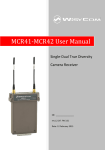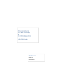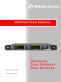
1
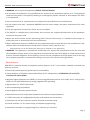
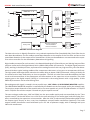
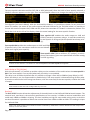
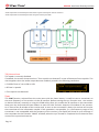
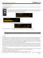
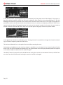
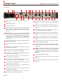
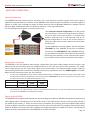
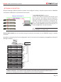
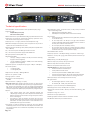
User Manual
Manual
MRK960 User
Rev.05 (ref. FW 1.1.0.w)
Date: 15 January 2014
Wideband
True Diversity
Dual Receiver
MRK960 dual true diversity receiver
Brief description
The MRK960 is a high performance microphone system suitable for broadcast and high professional application. Thanks to its exceptional selectivity and intermodulation immunity, MRK960 is able to operate even in
the presence of very high DVTB-T transmitter’s signals.
The extreme bandwidth agility of 370 MHz allows you to always find & work on the best frequencies available. MRK960 is designed to be:
••“easy & quick to use” thanks to automatic setup functions (i.e. frequencies, squelch), remote configuration
utilities (USB/Ethernet), a display with intuitive context menu navigation.
••“extremely flexible”, with an incredible frequency agility of 370 MHz; more than one rack can be connected
together thru a simple USB cable to act a multi-channel receiver. Moreover the DSP board allows the units
to work with several digital audio outputs (i.e. AES/EBU, Ethersound, …), with multi-companding compatibilities and other digital features.
••“best in class performances”, thanks to the latest Wisycom technology the unit has extreme RF sensitivity
and immunity and superb audio quality.
••“a durable & upgradable investment”, thanks to the very robust design (aluminum housing) and the possibility of upgrade/enhance units performances with simple slot in card (pc-like thru the DEXB expansion bus)
Moreover MRK960 system is already set up for the exclusive PTT function (remote command), developed and
patented by Wisycom and now appreciated in the broadcast world:
Simply pushing this button (PTT), the presenter causes the remote switching of the receiver’s outputline, from the “main line” to the additional “intercom line”, in order to be able to talk “off-air” directly
with the technical team. Then all PTT’s MICs can be connected in pre-fading allowing a clever intercom
setup.
Safety instruction
••Read this safety instruction and the manual first.
••Follow all instructions and information.
••Do not loose this manual.
••Do not use this apparatus under the rain or near the water.
••ATTENTION: supply the apparatus with a correct mains voltage and with the ground connection. Check the
power cord integrity.
••The power cord must be protected from damage.
••Do not install the apparatus near heaters or in hot environments, do not use outside the operating temperature range.
••Mount the apparatus as indicated in the instruction, do not block side grids for air ventilation.
••If the external air filter is mounted, clean it regularly.
Pag. 2
MRK960 dual true diversity receiver
••WARNING: do not open the apparatus, RISK OF ELECTRIC SHOCK!
••Do not open the apparatus, only qualified service technician are enabled to operate on it. The apparatus
needs servicing when is not properly working or is damaged by liquids, moisture or other objects are fallen
in the apparatus.
••Use only accessories or replacement parts authorized or specified from the manufacturer.
••Do not supply more than 7 apparatus MRK960 from the mains output, see power requirements for other
apparatus.
••Clean the apparatus only with dry cloths, do not use liquids.
••The ON/OFF is a double pole circuit breaker, but to ensure the complete disconnection of the apparatus,
disconnect the power cord.
••Report the serial number and the purchasing date in front of the manual, it is needed to have proper replacement parts or accessories from the manufacturer.
••When replacement parts are needed, use only replacement parts authorized from the manufacturer. Substitution with not authorized parts could result in electric shock, hazards or fire.
»»
Keep attention on all the labels with warnings or hazards on the apparatus.
••WARNING: The apparatus is intended for professional use; anyway the manufacturer alerts the user that
the headphone output power of the apparatus could exceed the level of 85 dB(A) of sound pressure level
and this could be dangerous for the hearings. Do not use the headphone with high power level or for long
time. Reduce the power or suspend the hearing in the case of any kind of hearing problem.
Main features
MRK 960 is a modular wireless-microphone receiver System in a 19” 1 unit module, stackable, with dual true
diversity receivers:
••Extreme RF (radiofrequency) performances and reliability.
••Tuning windows of 240 MHz with tunables filters (2 ch’s independent): 470/840 MHz (TV ch 21/67)
with internal active splitter
••Wisycom digital expansion bus (DEXB) for future upgrade/enhancement thru simple slot-in card (pc-like).
DEXB can host DSP (40bit dsp processing) upgrade cards providing:
••digital output (i.e. AES3, Ethersound)
••multi-companding compatibility
••future digital functionality enhancements.
••Balanced electronic AF output (low impedance transformer-coupled optional)
••2 USB’s connectors for configuration/monitor and cascade rack connections
••Automatic scan for best channels, squelch and other automatic setup
••Infrared interface (i.e. for system setup, microphone programming)
••Automatic transmitter re-programming (thru infrared, sync function)
Pag. 3
MRK960 dual true diversity receiver
••Software to monitor/setup units and with spectrum field analysis
••Ethernet 10/100 base Tx network interface for configuration/monitor
••Digital audio interfaces: AES/EBU (with word-clock in/out)
Optional:
••Ethersound® interface
••Push to Talk (PTT) function with audio exit and GPI signals (patented)
••Very low impedance transformer outputs
Technical description
The MRK960 is a professional dual diversity receiver for wireless microphones reception especially designed
for broadcast production, live stages, theatres and top professional applications.
It’s winning performances are:
••
High immunity on strong rf environment
••
Huge switching bandwidth
••
High audio performances and flexibility thanks to the digital processors
••
High reliability and durability
One of the milestones in the design of the MRK960 is high reliability: most of the circuitry of the receiver is
independent one from each other.
Here below a schematic with an overview of main receiver functions.
Starting from the antenna inputs, each antenna could be indipendently powered from a single power regulator monitored from the microcontroller.
For each antenna the RF signal is splitted in the receiver 1 and in the receiver 2 (antenna A and antenna B)
with a wide band splitter. In this way any one receiver could be tuned in any frequency of the switching range
(370 MHz).
Receiver 1 and 2 are true diversity receivers: each one is made of two receivers tuned on the same frequency,
hereafter called section A and section B. The receiver 1 section A and the receiver 2 section A are connected
to the antenna A, the receiver 1 section B and the receiver 2 section B are connected at the antenna B.
Each receiver has its own demodulated signal and its own RSSI signal (Receiver Signal Strenght Indication); a
microcontroller select or combine signals from section A & B to have the best audio. The demodulated signal
flows to the digital audio processor.
Pag. 4
Receiver - 2- B
Front panel
Receiver supervisor
microcontroller
and user interface
Analogue
output
Digital
output
B
Digital
audio
processor
AES3 Output
work clock
Ethersound
PTT
output
Receiver - 2- A
True Diversity
Control Rx 2
Antenna inputs
Receiver - 1- B
Line 1
Line 2
Com Rx 1
Com Rx 2
Earphone
Receiver - 1- A
Ear-ph Left
Ear-ph Right
Communic.
and control
interface
A
True Diversity
Control Rx 1
MRK960 dual true diversity receiver
INFRARED
Ethernet
USB
MRK960: main block diagram
The data sub carrier is digitally filtered to a very selective equivalent filter (bandwidth 3Hz). Each filter has its
own data demodulator, one for medium speed data detection at the output of the first filter and one at low
speed data detection at the output of the second filter. All the two demodulators are connected to the supervisor micro controller for the data battery detection and signalling.
Digital audio processor(for each receiver): the demodulated signal is filtered by an anti aliasing low pass filter
and then converted in the digital domain with a 96KHz 24bit audio A/D converter. The digital signal processor
(DSP), working in double precision, replicates all the analog functions with very high accuracy, ultra low distortion and without typical analog problems like components tolerances or long term or temperature drifts etc.
The high speed audio algorithms maintains the audio delay at about 0.390 milliseconds, making it ideally for
live events and to keep audio delay as short as possible. The DSP unit also filters and demodulates the data
carrier and communicates all the parameters and informations to the supervisor micro controller. The audio
output goes to the digital outputs (AES3) or is converted in the analog domain with a high quality 24 bits
96KHz D/A converter and an anti-aliasing filter.
The analogue audio signal is routed in three parallel ways, LINE, COM and HEADPHONE MONITOR amplifier.
The HEADPHONE MONITOR amplifier is controlled by the buttons on the front panel and by the volume knob.
The monitor output depends on the squelch and on the tone squelch only in the TSQ ON selection. In TSQ OFF
and in TSQ ADV the monitor output is muted only by the squelch control.
The two analogue audio ways, LINE and COM, has the same audio quality and are controlledy by the “Tone
squelch matrix”. Each audio driver has a VCA for the soft switching of the audio signal and the muting functions, controlled by the supervisor microcontroller. After the VCA, an electronically balanced amplifier drives
the output signal, directly or thru a very low impedance screened audio transformer (optional). The audio
output without transformer could withstand up to +52 Vdc of phantom supply with no damage and up to
100V with transformer.
Pag. 5
MRK960 dual true diversity receiver
User guide
A
B
C
D
E
Front panel functions
MRK960 allows an easy and quick configuration using buttons, push knobs and displays.
The front panel is functionally divided in the following section:
A
Scan & Squelch: automatic scan and squelch settings;
B
Infrared: remote controlling and MIC setup through infrared interface.
C
Receiver 1: “receiver 1” configuration and monitor of radio/deviation levels.
D
Receiver 2: “receiver 2” configuration and monitor of radio/deviation levels.
E
Monitor: monitoring audio output on headphone jack (6.3mm - ¼”).
Power & Booster: powering ON or OFF the receiver and the antenna boosters
SCAN & SQUELCH & INFRARED
The function SCAN initiates an automatic procedure for the choice of the less noisy channel in the selected
group of channels; the scan function measures the floor noise of all the channels of the selected group and
show the result in the display. This is a quick way to find the best channels to use in the selected group. When
pushed the scan button, it is needed to setup or confirm the group of channels for the scan.
SQUELCH initiates the automatic procedure to setup the level of the squelch. This is an automatic
way to quick setup the squelch for the current frequency. The transmitter must be off, then push
SQ button to let the system find the optimal value. You can later accept, modify or discharge this
setup.
IR interface window: for communications between the MRK950 and a transmitter. You have to
put the IR interface of the transmitter, with the IR interface active, in front of this window. This is
needed for example in the SYNC function.
Pag. 6
MRK960 dual true diversity receiver
RECEIVER 1 and RECEIVER 2
A
B
C
D
Area A: 3 LED bars:
• two bars for the RF levels in dBuVolt (diversity A & B antenna level),
• FM modulation of the received channel (modulation in % referred to the nominal deviation)
• LIN: audio in line output active
• COM: audio in com output active (optional)
• GPI: g.p.i. command thru opto-isolated relay, active (optional)
• DATA: data subcarrier from microphone transmitter detected
Area B: display (256 x 64 pixels yellow OLED display)
Area C: 3 push buttons (membrane).
The function of each button (upper, middle and lower) will be readable from the context menu on the
display.
Area D: Push rotary knob and light indicator
Warning (YELLOW) and Alarm (RED) light indicator:
• Yellow Fixed light indicator (Warning) when there is no audio in both the audio outputs (COM and
LINE)
• Red Slow Blinking light indicator (Low Alarm) when the battery level of the transmitter is ≤25%
• Red Fast Blinking light indicator (Medium Alarm) when the battery level of the transmitter is ≤12%
• Red Fixed light indicator (High Alarm) when a booster (A or B) has a short circuit. Moreover the following message appears on the OLED display: “Over Current on antenna A/B”
MONITOR
Monitor 1 and 2:it activates monitor audio on jack output (6.3mm - ¼”) for receiver
1 and 2, respectively (a green LED is lighted when audio is enable). Audio level can be
adjusted with the rotary knob. The red led (CLIP) indicates a clipping in the audio monitor output.
POWER & BOOSTER
BOOSTER:it activates antenna powering (boosters) with 12VDC (200mA max) and the
green LED is lighted. Blinking LED indicates a faulty condition, in this case power down
the device and check for short circuits or overloads in the RF cables or boosters.
Booster supply for antenna A and antenna B are indipendent, switchable from the RADIO > OPTIONS menu.
POWER: ON/OFF square powering button turns on/off the receiver. When in OFF position both phases are disconnected from power.
Pag. 7
MRK960 dual true diversity receiver
LCD display: Main view
All the basic information on the receiver status are readable in the main view of the LCD display.
The main view has the following info:
1 receiver name,
2
2 current tuning frequency
3 current channel number
4 current group number and group name
5 TV channel used for the current frequency
6 Tone Squelch current setup
7 LOCAL or REMOTE receiver management, via USB
or Ethernet connection
1
12
3
4
5
11
6
7
8
9
10
8 Squelch level (microVolt)
9 NET connection to a host PC (USB or Ethernet)
10 Analog audio output level at nominal FM deviation
11 status of the output lines (audio line, audio com, gpi) and detection of the digital data carrier (i.e. transmit-
ter battery data carrier or tone squelch),
12 transmitter battery charge status.
Thru the main menu on the LCD display and the LED bars for the RF level and modulation the user has the
complete monitoring in real time of the wireless channel in use.
Menu tree
To access the configuration menu of the receiver is necessary to press the rotary knob (at the right of the display). This allows you to access the main menu.
Pressing firt the rotary know shows a hidden window (area 11 the image
of the main view) with three main headings: “RADIO”, “AUDIO”, “SYNC“.
To activate one of the items in the menu, press the corresponding button
to the right of the display (see picture hereafter).
Press the knob
RADIO
Pag. 8
AUDIO
SYNC
MRK960 dual true diversity receiver
Radio menu
The first item on the menu tree is “RADIO”. Pressing the upper button (RADIO), you go at the RF functions
menu of the receiver, as shown below:
Pag. 9
MRK960 dual true diversity receiver
Chan-Group
The CHANNEL-GROUP item enables the user to edit channel, channel group and frequency of the selected
items. Change, rotating the knob, the channel or the group of channels and confirm or exit with the buttons.
To edit the frequency of selected channel, press the middle button and change it with the knob. Press the
knob to move between MHz and KHz. Confirm or exit with the buttons.
As shown in the above picture, the display area has 3 rows with:
1] Channel number (0 to 60) and Channel frequency (in
25kHz step)
2] Group number (1 to 40) and group name (8 char.)
3] Group description (30 char.)
The MRK960 has 40 groups of 60 channels each. Normally this is too much for wireless microphones applications.
Connecting with computer with WISYCOM MANAGER software, it is possible to hide single channels or even
complete groups of channels: once hidden those items are not shown anymore on the channels or groups
selection. To show channels or groups hidden use again the WISYCOM MANAGER software.
Using this software it is also possible to lock channels or groups. When a channel is locked, it is not possible to
change the frequency from the front panel of the receiver. Locking a group means that all channels are locked.
When a channel or a group are locked, at the left of the group name in the Chan-Group menu will appear a
lock icon as shown in the picture below. When the lock picture is shown, the central button is not displayed,
thus changing frequency is not possible.
Gr. name
The second item on the radio menu is GROUP NAME; with
this function is possible to assign or change a name to a
group of channel. This short name (8 character) is displayed
at the right of the group number in the main display view.
First chose the the group and then press the knob. You will
be able to edit any character of the group name rotating the knob. Push the knob to edit the next character.
Confirm or exit with the buttons.
Squelch
The SQUELCH function allows to assign a value at the squelch
of the receiver. Rotating the knob it is possible to change current squelch level from OFF (it means no audio squelch) to
1mV. Pressing the knob you could setup the desired level and
also configure you measurement unit between microVolts
and dBµV. At the end confirm or exit with the buttons. There is also an automatic procedure to set up the
squelch level, it will be discussed later in this document at the Autoset SQUELCH item.
Pag. 10
MRK960 dual true diversity receiver
Walk test
The WALK TEST function records the RF level of the two antenna inputs, separately, for a total time of 90 seconds. Using the first button, it is possible to choose what to plot: the rf level of the antenna A or B, the Max
value between antenna A and B or both antenna levels separately. Press START and walk on your area with a
wirelss MIC (transmitting at the current frequency) while receiver records all received RF levels. At the end of
the sweep time it is possible to have a look on the graph and check if there are some “hole of RF signals” and
evaluate your wireless coverage.
Finally push the 3rd button (EXIT) to leave this fucntion. As “rule of the thumb”, the signal coverage of the
stage could be considered good if, in all the stage, the signal “MAX AB” is never lower than 10µV or 20dBµV.
The plot in the picture, shows a very low coverage with some areas not covered by the two receiving antennas.
In this case probably the position of the antennas must be changed and/or the gain of the boosters adjusted.
Note: the unit for RF level is the same chosen for the squelch level (dBuVolt or uVolt)
OPTIONS:
Name
The options NAME allow you to change the name of the receiver. This is the name displayed in the top of the
display in the main view and is the name sent to the transmitter with the sync function (for transmitters with
this advanced capability).
Use the knob to change the name and the buttons to save
or exit from the function (12 alphanumeric characters: A-Zaz0-9, case-sensitive).
Display Brightness and Timeout
Display brightness allows to change the brightness of the display from 1 to 15 level (step 1 dB).
Display LOW Timeout [0÷120 sec] controls display behaviour as follow:
- After a first timer timeout without any input on the receiver (buttons or wheel) the display gost on “REDUCED BRIGHTNESS MODE”
- After another timer timeout, the receiver goes into “LOW BRIGHTNESS MODE”, and leaves current menu to
be back on TOP MENU.
Display OFF Timeout: [OFF, 5÷240 min] after the timeout without any input on the receiver (buttons or wheel)
the display switches off. (OFF=display always power on.)
NOTE: Each receiver has indipendent display parameters.
Boost active on antenna
allows to select which antenna input (A, B or A+B) has to be powered on by pressing BOOSTER button
from the front panel.
Pag. 11
MRK960 dual true diversity receiver
Info
the INFO function shows many important features or information of your MRK960 receiver:
»»
»»
»»
»»
»»
»»
»»
»»
»»
»»
ange: info about the frequency limits of the receiver.
R
Temp: internal temperature of MRK960.
Ant. A and Ant. B: the measure of the output current for powering the boosters connected on antenna
input A e B connectors. The current measurement is active only when boosters are switched on. The
booster supply voltage is 12 Volts.
Serial: serial number of the MRK960 receiver.
Errors: number of internal errors detected by the receiver, useful for service or maintenance.
App: release version of the main application firmware.
App bl: release version of the main application firmware updater (bootloader).
Netw: release version of the network communication firmware.
Netw bl: release version of the network communication firmware updater (bootloader).
DSP: release version of the DSP firmware.
Note: the complete software and hardware status is displayed switching ON the receiver with a knob pressed. Press this knob a second time to exit this function. RF test
This menu gives some information of the RF signal measured.
Note: low level of Tsq. mod means that the Tone squelch is not detected from the receiver
Factory preset
The FACTORY PRESET resets the following setups to factory defaults: tone squelch (OFF), noise reduction
system (ENR), audio output level (12dBu), cal tone (OFF), audio matrix, booster supply (OFF) and headphone
selection (OFF).
Note: receiver names, frequencies, groups or channels information are NOT changed. Pag. 12
MRK960 dual true diversity receiver
Audio menu
The second item on the menu tree is “AUDIO”.
Noise Red
The NOISE REDUCTION SYSTEM is used to select your current noise reduction system in the audio path.
Thanks to the DSP board, it is possible to choose different types of audio processors. MRK960 supports, as
standard configuration, the following type of “Companding system”:
NONE-d50
NONE-d75
ENR-WISY
ENC-WISY
NO compander, 50µs de-emphasis
Analogue battery data & PTT (Wisycom®)
NO compander, 75µs de-emphasis
Analogue battery data & PTT (Wisycom®)
Wisycom ENR compander, noise optimized
Digital battery data & Ptt (Wisycom®)
Wisycom ENC compander, voice and high-fidelity optimized
Digital battery data & Ptt (Wisycom®)
Use the buttons to save or exit from this function. Depending on selected NOISE REDUCTION SYSTEM, tone
squelch function and transmitter battery status could be enabled or disabled (since not all the wireless microphones have this enhanced functionality).
Tone sq.
The TONE SQUELCH function is an advanced function (whose behaviour depends on selected noise reduction
system). This chapter explains TONE SQUELCH operations when associated to a Wisycom wireless microphone
with the ENR-WISY or ENC-WISY as active noise reduction system. Other types of wireless microphones could
have different behaviour or could not work properly. Here-after the complete tone squelch function, whenever the receiver does not have all the options installed, some functions will be hidden.
Pag. 13
MRK960 dual true diversity receiver
The tone squelch selection could be OFF, ON or ADV (advanced). After the SAVE of tone squelch selected, a
CONFIG submenu appears on the right. Enter on the CONFIG submenu to change the setting of the choosen
Tone Squelch (see matrix below). With the knob and the buttons, it is possible to choose, for any one of the
three TSQ modes, the status of the audio outputs LINE and COM and in the TSQ ADV mode it is possible to
choose the status of outputs LINE, COM and GPI, when the transmitter PTT button is released or pushed. The
dot in the circle on the left of the display shows the actual setting for the tone squelch function.
Tone squelch OFF enables the audio output on LINE and
COM (if present) connectors always, it could be muted only
by the squelch on RF signal (the RF squelch has always priority).
Tone squelch ON enables the audio output on LINE and COM
(if present) only if the transmitter sends the correct identification tone signal (tone squelch).
Tone squelch ADV (with or without PTT options), on microphone transmitters, gives more possibilities of audio routing
and GPI signalling.
Note: the tone squelch could not substitute the squelch on the RF signal level. For the best performance of the receiver it is better to use the SQUELCH & TONE SQUELCH together.
Audio delay at TSQ_ON (ms)
With this parameter, it’s possible to enable a delay on the activation of the audio when the tone squelch is
ON. If the tone squelch is set to ADV (advanced), this delay is not enabled.
This delay is set to 500ms by default but it’s possible to change it from 100 to 2000ms (step 100ms) or OFF.
When the delay is set, the output audio is enabled only if the tone squelch is detected during all delay time.
It permits to avoid that a brief strong interference, with the same freq of the tone squelch, enables the audio
in output.
Note: this feature is available from firmware version 1.1.0.w. In the previous FW versions the delay
was forzed to OFF and not configurable by the user.
Out level
The OUT LEVEL function allows the adjustment of the audio level on the LINE and COM balanced outputs. The
nominal level, used also in the technical specifications of the receiver, is 12dBu at nominal modulation and
could reach 18dBu to 20dBu in clipping. This level could be too high for some audio mixing units, so with the
out level function it is possible to reduce the nominal level from 12dBu to 6dBu or 0dBu. This setting is unique
for LINE and COM.
Note: the audio output level could be further reduced by 30dB with a switch below the XLR output connector, in the rear panel.
Pag. 14
MRK960 dual true diversity receiver
Cal. tone
The CALIBRATION TONE function generates a tone (at specific frequecies) or a sweep of tones at the audio
outputs. Change the value of the following parameters according to the desiderable calibration tone:
»»
»»
»»
»»
»»
»»
ode: select the type of calibration tone (Tone/Sweep)
M
Out: select the outputs for the calibration tone (only LINE, only COM or LINE and COM together)
Level: select the level (-6 dBFS or -26 dBFS)
Frequency (only for Tone): 444/442/440/1000Hz
Freq step (only for Sweep): ocatve ÷ 1/24 octave
Time step (only for Sweep): 1sec/100ms
With the buttons it is possible to start, stop and exit from the tone generation. The output not selected for the
tone generation will be muted.
When the tone is active at least in one output, the led bar of the deviation indicates the level selected.
Frequency diversity
This option is normally set to OFF. Set to YES when you need:
••to increase the reliability in case of failure
••to increase the reliability in case of transmitter batteries empty
••to increase the security against fading due to reflections on the radio link
When a receiver is set to frequency diversity YES, the audio output is calculated from the best RF signal received from the two receivers.
WARNING: two transmitters tuned with the two receivers must be placed on the same audio source and must
have the same configuration (ex. gain, tone squelch setting, RF power, distance from the audio source….).
NOTE: the Noise reduction can be different.
Note: Frequency diversity in each receiver can be set independently.
Note: With frequency diversity enabled (set to YES), the Tone Squelch menu allows only the setting options ON and OFF (the ADV option is not allowed).
Frequency diversity example:
RX1 tuned on f1 with Frequency Diversity set to YES.
RX2 tuned on f2 with Frequency Diversity set to NO.
Pag. 15
MRK960 dual true diversity receiver
Audio output RX1 is calculated from the best RF signal received from the two receivers.
Audio output RX2 is calculated from the RF signal received from RX2.
TSQ detect alarm
This option is normally disabled.
If enabled, the receiver shows an alarm “Tone squelch not detected” in case of absence of tone squelch. The
alarm appears when the audio output becomes suddenly muted in the following conditions:
••“AUDIO>Tone sq” set to ON or ADV
••RF level > squelch
••Tone squelch not detected
Sync
The SYNC function, selected from the main menu with the lower button, is useful to tune a transmitter on
the same frequency of the receiver via the IR interface. Before starting the sync function tune the receiver
on desired channel, manually or using the SCAN utility. After this, enable the IR interface on the transmitter.
Now press the knob and the lower button to start the SYNC function. Keep the IR window of the transmitter in front of the IR window of the receiver and, as soon as the connection is done, the receiver will send to
the transmitter all the information needed. If the operation is not possible, (i.e. the frequency range of the
transmitter is not compatible with the frequency of the receiver), the display will show an error message. If
the transmitter has the function “NAME” enabled, when the sync function is completed it will show the same
name of the syncronized receiver.
Pag. 16
MRK960 dual true diversity receiver
SQ (squelch autoset)
The SQUELCH AUTOSET function helps the user to set the squelch level of the receiver at a good level for the
selected channel.
After pressing the SQ autoset button, the two receivers ask to switch off the transmitter and
then, after the user confirmation (on one receiver or all the two receivers at the same time), it
starts to measure the noise in the selected channel.
A few time later, after some calculation, the receiver proposes the new squelch level.
The user could then accept, refuse or modify it by means of the buttons and of the knob.
Note: during the Autoset SQUELCH function it is not possible to change the unit of the squelch voltage.
SCAN
The SCAN function is very useful to discover the best channels to use (the channels with lower RF noise) in
the selected group. After pressing the SCAN button, both receivers are ready to start with the SCAN function.
It is possible to select the receiver 1 or the receiver 2 or both (i.e. simultaneously scan on different groups).
With the first menu on the display it is possible to choose the group of channels for the scan and, pressing
the knob, is possible to define a reference line drawing in the final scan result graphic, just for user reference.
Pressing the knob the focus change between REF LINE and GROUP.
Pressing the START button, an alert window remind the user to switch off all the transmitters before starting
the SCAN, press START again and the SCAN function will start. At the end of the analisys, on the display it is
possible to see the graph of the RF levels measured in each channel and, rotating the knob, it is possible to
move the marker on the bottom of the graph just to see the channel number and the RF level measured for
that channel.
Pressing the knob it is possible to have a graph in rank order instead of channels order, so, it is very simple in
rank order to find the less noisy channels because they are in the left part of the graph.
The marker is always active rotating the knob.
Pressing the knob the graph changes between rank order to channel order again.
For terminating the SCAN function, press the lower button on the right of the display.
Pag. 17
MRK960 dual true diversity receiver
In the above picture a typical graph of the scan function (only the graph area of the display). This graph, ordered by channel numbers, shows the RF levels in dBµV for each channel in the selected group (i.e. Ch: 00).
Rotating the knob the small arrow cursor moves from a channel to the next one; on the right of the graph it is
possible to see the rank of the channel selected by the cursor, its number, its frequency and the RF level. Pressing the knob the order of the graph became the rank, not the channel number. In this way it is more simple to
choose channels with lower RF noise, they are in the left part of the graph. See at the picture below:
In this graph the channels are ordered by rank. Turning the knob it is possible to change the channel and reading its number, frequency and level of RF noise.
The horizontal dashed line is the squelch level set before starting the scan.
Connecting an headphone at the monitor output, is possible to ear the signal in the channel selected by the
knob. If the RF signal is below the squelch level, the upper button near the display disable/enable the squelch
so the audio output is enabled also for weak RF signal.
The SELECT button is the exit from the SCAN function tuning the receiver on the selected channel, the EXIT button exits from the SCAN function leaving the receiver channel unchanged.
Pag. 18
MRK960 dual true diversity receiver
OPERATING INFORMATIONS
RF Level led bars
Two RF level led bars for each receiver indicate measured RF level at the antenna input of the receiver in the
selected channel. For a typical diversity reception it is a good starting point to consider that the two signals
should have the same average level over time, but this could be different while moving the transmitter on the
stage. The important issue is that moving the transmitter on the stage, the diversity has to work switching
from one receiver to the other receiver as indicated by the two blue leds on the top of the bars. When the
RF levels of the two inputs have similar level, the diversity control enable the two receiver at the same time,
further increasing the S/N ratio at the audio output.
Modulation led bar
The third led bar of each receiver indicates current channel modulation as percentage of nominal deviation
(not the audio output level). The difference between modulation and audio level is because normally there is
a preemphasis on audio transmission and some manufacturer uses different compression values and different
audio frequency equalization. Therefore to have the maximun efficiency of the radio channel it is important
to use the highest modulation bandwidth possible, in respect to the dynamic range of the audio signal and the
manufacturer specifications. If the receiver MRK950 has the DSP board option, the scale of the modulation
will be changed according to the nominal modulation of the type of microphone and manufacturer selected
in the NOISE REDUCTION SYSTEM. The modulation led bar is blank when the squelch and/or the tone squelch
opens the audio output circuit (or if there is no modulation on the transmitter, of course). Adjust the gain of
the audio chain in the transmitter to have in the maximum modulation peaks the 100% of modulation bandwidth, leaving the next 6dB of modulation margin before clipping (red PEAK led) for extra sound pressure
margin. If the audio level is not exactly known, be conservative and adjust the microphone gain in a lower
position to avoid clippings during the working session.
Battery indication
On the main display of each receiver is always well visible the battery status of the transmitter (area 12 of the
main view). The resolution of the indication depends on the transmitter. Wisycom transmitters send 8 levels
of battery charge status, other competitors 6 or 4 or 3 level (full, half, empty).
When the transmitter is a Wisycom, the display of the batteries indicate the correct icon and the percentage
of the charge but, when the charge reach the 25% the battery area on the display became flashing, when the
charge reach the 12,5%, the illumination of the display is flashing to give an high visibility alarm to the user.
Pag. 19
MRK960 dual true diversity receiver
Rear panel
1
2
4
3
25
24
5
23
6
22
1 1Mains output. Do not connect more than 8
units.
2
Mains socket input.
3
Mains fuse (2A-T).
4
Ethernet connector RJ45 for LAN connection of
the receiver. The leds on the connectore indicate the status of the connection (Link and Activity).
5
AES/EBU XLR 3 pin output connector, digital
audio output transformer isolated, balanced.
This is part of the AES/EBU optional board, toghether with 6, 7 and 22. Here it is possible to
install different option like Ethersound© I/O.
(Optional)
7
8
9
27
21
10
20
11
19
12
18
13
14
15
17
16
26
17 Switches for shorting the pin 1 of the XLR connectors of receiver 1 to the receiver ground or
not.
18 Switches for attenuating the audio output level on the XLR connectors. The attenuation is
30dB.
19 Unbalanced LINE audio output of receiver 2,
1/4” (6,3mm) stereo jack socket.
20 Switches for shorting the pin 1 of the XLR connectors of receiver 2 to the receiver ground or
not.
21 Switches for attenuating the audio output level on the XLR connectors. The attenuation is
30dB.
6
Word clock input for external syncronization of
digital audio output.
22 Word clock output, for daisy chain connection.
BNC connector. (Optional)
7
75 ohms termination switch for word clock input.
8
Antenna B input, BNC connector, DC output for
booster power supply.
23 LINK connection, for cascade connection of receivers, for remote control functionality. USB-A
connector.
9
XLR 3 pin male connector, COM audio output of
the receiver 2, balanced. (Optional)
10 XLR 3 pin male connector, LINE audio output of
the receiver 2, balanced.
11 GPI output of the receiver 2, 1/4” (6,3mm) stereo jack socket. (Optional)
12 XLR 3 pin male connector, COM audio output of
the receiver 1, balanced. (Optional)
13 XLR 3 pin male connector, LINE audio output of
the receiver 1, balanced.
14 GPI output of the receiver 1, 1/4” (6,3mm) stereo jack socket. (Optional)
15 Antenna A input, BNC connector, DC output for
booster power supply.
16
Unbalanced LINE audio output of receiver 1,
1/4” (6,3mm) stereo jack socket.
Pag. 20
24 USB-B connector for PC connection if this
MRK960 is a subnet controller. If this MRK960
is part of a subnet, this connector must be connected to the LINK connector of the previous
MRK960.
25 Product identification label.
Antenna A output, BNC connector (for antenna
26 splitting)
27
Antenna B output, BNC connector (for antenna
slipping)
MRK960 dual true diversity receiver
RECEIVER CONNECTION
Antenna Connection
The MRK960 has two antenna inputs, necessary for a true diversity reception system. Each input signal is
splitted for the two diversity receivers on the MRK960. Each antenna input could deliver a booster supply of
200mA at 12Vdc; this is enough to supply an active antenna like the Wisycom LBNA and a booster like the
Wisycom BAA, needed only when the antenna cable has a very high attenuation.
For connecting more receivers on same antennas use
••the antennas cascade configuration as in the picture
(typ. 8 receivers). Connect the output antenna connector to the input of the next receiver. in reverse order
between antennas side A and antennas side B. Using this configuration in case of one of the receiver is
faulty, the other receivers can continue to work (without diversity).
••active wideband antenna splitters like the Wisycom
SPL214AW for four MRK960 (8 wireless microphone
channels) or the SPL218AW for eight MRK960 (16 wireless microphone channels). More channels are possible
combining more splitters. In this case the active antennas and the boosters will be powered by the splitters.
Analog audio connection
The MRK960, in the full optional audio output configuration, has three audio outputs for each receiver, two
balanced with XLR connector and one unbalanced with a 1/4” (6.3 mm) stereo jack connector. The unbalanced audio output has the same audio signal of the LINE output. The balanced audio outputs could be
electronically balanced or transformer isolated with very low impedance when the TRAFO option is installed.
Below the XLR connectors there are two switches:
»»
the left one (LINE/MIC) inserts a fixed resistive attenuator of 30dB on the audio output; the audio levels
on the XLR connector, according to the setting of the “Out level” and to the setting of the switch below
the XLR connectors, at nominal modulation, are:
Att. 0dB
Att.30dB
»»
Out lev 12dBu
Out lev 6 dBu
Out lev 0 dBu
12 dBu
-18 dBu
6 dBu
-24 dBu
0 dBu
-30 dBu
the switch on the right (LIFT/) cuts the connection beetween the pin one of the XLR connector and the
ground of the MRK960 to avoid ground loops.
Digital audio AES/EBU
The MRK960 has an digital audio output channel according to the AES3 or AES/EBU standards for professional
24 bit digital audio. The left channel of the AES3 stream is the audio of the receiver 1 and the right channel is
the audio of the receiver 2. When no word clock is connected, the sampling rate of the digital audio output
is fixed at 48KHz, internally crystal generated; with the external word clock the sampling rate could be from
32KHz to 108KHz. The word clock input could be left at high impedance or loaded to 75 ohms. The word clock
output could be connected to the next MRK960 or could be left open.
Pag. 21
MRK960 dual true diversity receiver
Digital audio Ethersound©
The Ethersound option on the MRK960 adds the capability of a connection beetween the MRK960 and an
Ethersound audio distribution system. This option adds two RJ45 connectors for the ethernet cables, one is
the input and the other is the output of the Ethersound interface.
Link Ethernet 10/100 Mbit/s
The Ethernet interface is used to connect an MRK960 to an host PC for remote monitoring. The “WISYCOM
MANAGER” is the PC software for the complete remote monitoring and managing several MRK960 also connected thru an USB cascade.
WISYCOM MANAGER is able to find a configure network parameter of a MRK960 in ethernet connection without knowing its IP address (this is done thru a broadcast discovery). Near the ethernet connector there are
two led lamps, one for the connection check and one for the data monitoring.
A receiver connected to a PC could be an subnet controller for other receivers if the other receivers are connected in a chain with USB cables as shown on the picture “4 rack USB CASCADE”.
USB connection
The MRK960 comes with an USB 1.1 interface that has priority over ethernet connection (in case of USB port
connected to a PC, the ethernet port is disable). Near the USB connector there is another connector named
LINK. This connector could be connected to the USB port of the next MRK960 with an USB-A to USB-B cable
to build a chain of receivers. The maximum number of receivers in a chain is four. The receiver with the USB
connector free is the subnet controller receiver (the one in the upper position on the picture). It must be connected to a PC by means of the USB port or by means of an ethernet connection. Once connected, start the
WISYCOM MANAGER software to manage the array of receivers (more details on software manual).
Pag. 22
MRK960 dual true diversity receiver
NETWORK CONNECTION
Wisycom Manager software allows to monitor and configure remotely complex systems base on MRK960s
connected in USB chain or thru ethernet connection.
4 racks USB CASCADE(8 receiver):
the first is the subnet controller that control up to
other 3 receiver. This entity is seen as single 8 receiver and using the ethernet port of the subnet
controller can also be remoted in a computer network. This way the system has also the information
on every single MRK960s location allowing very effective configuration and scene backup.
Note: it is not possible to connect more than 4 receivers MRK960 in a subnet USB
Several USB cascade can be connected using the ethernet connection on each MRK950 acting as cascade
controller.
Hereafter an example of a 12 rack configuration, there is no limits to the complexity manageable on Wisycom
Manager software.
ETHERNET
HUB - SWITCH
ETHERNET
LINK
LINK
LINK
LINK
LINK
LINK
LINK
LINK
LINK
Note: If using MRK960 with antenna cascade (using its integrated splitter), the MRK960 acting as
“subnet controller” must be also the receiver connected with antennas and boosters. This is
to be able to manage and monitor voltage and current on antenna boosters.
Pag. 23
MRK960 dual true diversity receiver
Technical specification
••Two indipendent receivers tunable in all the specified frequency range
••Frequency range:
»» 470/840 MHz (TV ch 21/62)
with internal active splitter
••Memorized channels: up to 2400 divided in 40 groups with 60 channels each
••Frequencies: microprocessor controlled PLL frequency synthesizer circuit,
with 25 KHz minimum step (others on request)
••Frequency error: < ± 2.5 ppm, within the rated temperature range.
••Modulation: FM (50µs de-emphasis), other de-emphasis can be pre-set on
request and can be recalled from the menu.
••Nominal deviation: ±40 KHz @ 1 KHz, ±65 KHz peak (Max acceptable deviation = ±80 KHz).
••Noise Reduction system : compander circuit, can be pre-set (or switched
off) to the following modes:
»» ENR (Wisycom Extended-NR) as default
»»
CUSTOM (to be compatible with other brands transmitters)
••AF line output
»» electrically balanced on XLR-3M connector (option XRL, transformer with 30 Ohm imp.)
»»
AF line output level: +12 dBu (3.1 Vrms) @ nominal deviation
(could be individually attenuated by 30dB by means of a switch on
the back panel under the XLR connectors)
»»
AF line output peak level: +20 dBu (7.75Vrms)
»»
AF line output connector: XLR, pin 1 could be grounded or floating
by means of a switch on the back panel under the XLR connectors.
Could withstand up to +52 Vdc of phantom supply
••“A” / “B” antenna inputs: with BNC type female connectors.
••“A” / “B” antenna input booster supply: 12Vdc 200mA max.
••AF bandwidth: 40 Hz ÷ 20 KHz
••RF input impedance: 50 ohm (SWR < 1:2)
••Frequency response: < ±0.5 dB (±0.2 dB typ.) in the 50 Hz ÷ 19 KHz range
••Sensitivity [with ENR]:
»» < 0.9 µV ( -1 dBµV), for SND/N = 52 dBA, in the whole switchingrange [Rms value A weighted]
••Distortion: < 0.3 % (0.1 % typ.) @ peak deviation, ENR noise reduction system enabled
»»
< 10 µV (+20 dBµV), for SND/N = 115dBA, in the whole switchingrange [Rms value A weighted]
••Amplitude response: < 0.2 dB (for RF input signal: +4 dBµV ÷ +120 dBµV)
••Co-channel rejection:
»» > -3.5 dB @ 2 µVRF
»»
> -1.5 dB @ 100 µV RF
••SND/N ratio [1] > 115 dB (118 dB typ.) [2]
••Monitor output: 1/4” (6.3 mm) stereo jack connector
••Monitor output level: max 6 Vrms / 150 ohm
••Monitor out impedance: 100 ohm for auricle
••AES/EBU (AES3) board, externally synchronized:
»» balanced transformer isolated output
»»
24 bit professional audio stream
••Adjacent chan. selectivity: > 90dB @ ±300 KHz
»»
word clock input from 32KHz to 108KHz, BNC connector
••Spurious rec. rejection: > 90 dB
»»
word clock input impedance: 75Ω or high Z externally switchable
••IF image rejection: > 110 dB
»»
word clock output on BNC connector for cascading more units
••IIP3 (Input 3° order Intercept Point):
> 20 dBm
••Spurious emissions: < 1pW (typ. = 0.1 pW)
••DSP audio board, 40bits floating point DSP processor for high dynamic
range low noise multicompander audio processing and digital data detection. Thanks to the latest DSP class “shark” by Analog Design (2Gigaflops
40bit power), providing the highest audio quality (40bit floating point) and
a delay of only 0,39 msec (AES3 output) and 0,46 msec (analogue output)
••Squelch :
»» signal strength squelch: with menu adjustable threshold and
“adaptive type” working: the receiver adapts itself automatically to
different conditions of both medium strength and speed variation
of the received signal;
»»
tone-squelch: it works by decoding the special key, sub-carrier
(digitally modulated) present on the carrier of the actual Wisycom
transmitters. The tone squelch function can be inhibited for compatibility with other types of transmitters.
••Tone-squelch: it works by decoding the special key, sub-carrier (digitally
modulated) present on the carrier of the actual Wisycom transmitters. The
tone squelch function can be inhibited for compatibility with other types
of transmitters
Pag. 24
••Diversity technique: true-diversity (Twin receiver circuits)
••Bar-graph meters:
»» RF field strengths (both “A” and “B” inputs) »»
AF deviation (5% ÷ 150%), with peak-hold mode
••Displays: nr. 2, one each receiver, 64 x 256 OLED (yellow)
••Calibrating AF tone: 1 KHz, +12 dBu (other on request)
••Powering: 99 ÷ 138 Vac and 187 ÷ 264 Vac, with automatic switching / 100
VA max
••Temperature range: -10 ÷ + 55 °C
••Dimensions: 19”/1U, depth 370mm
••2 USBs type A/B for network connection and devices cascade
••10/100 Base TX Ethernet port on RJ45 connector
MRK960 dual true diversity receiver
Options specifications:
••Low impedance transformer on audio lines (option XRL950, XRC950): Analog audio outputs are galvanically isolated by means of a high quality low impedance shielded transformers.
»»
»»
utput level: 12dBu nom., 18dBu at max FM deviation
o
output impedance: < 30Ω (e.g. could drive at least 300m of high quality twisted pair audio cable without
degradation in frequency response)
••COM audio output (option PTT950): same specifications as LINE audio output
••GPI output (option PTT950): normally open opto-relay isolated output,
»»
»»
AC/DC 56Vpk max - 100mAmax.
10 ohm max on resistance.
»»
1/4” (6.3 mm) stereo jack connector (2 pins for relay contact + receiver ground)
••Ethersound® (option ETS950): interface enable the connection of the MRK950EX on a Ethersound® network
for multichannel digital audio distribution on a single cat.5 Ethernet compatible cable.
»»
Needs DSP audio board installed.
»»
Two RJ45 connectors for input and output data lines
Pag. 25
MRK960 dual true diversity receiver
ENVIRONMENTAL INFORMATION
Applicable in the European Union and other European countries with separate collection systems
Disposal of Old Electrical & Electronic Equipment (2002/96/EC)
This symbol indicates that this products shall not be treated as household waste. Instead it shall be handed over to
the appropriate collection point for the recycling of electrical and electronic equipment. The recycling of material will help to conserve natural resources.
ITALY ONLY
Obblighi di informazione agli utilizzatori
ai sensi dell’art. 13 del Decreto Legislativo 25 luglio 2005, n. 151 “Attuazione delle Direttive 2002/95/CE, 2002/96/CE
e 2003/108/CE, relative alla riduzione dell’uso di sostanze pericolose nelle apparecchiature elettriche ed elettroniche,
nonché allo smaltimento dei rifiuti”
Smaltimento di apparecchiature elettriche ed elettroniche di tipo professionale
Il simbolo del cassonetto barrato riportato sull’apparecchiatura o sulla sua confezione indica che il prodotto alla fine
della propria vita utile deve essere raccolto separatamente dagli altri rifiuti.
La raccolta differenziata della presente apparecchia¬tura giunta a fine vita è organizzata e gestita
dal produttore. L’utente che vorrà disfarsi della presente apparecchiatura dovrà quindi contattare il produt¬tore e seguire il sistema che questo ha adottato per consentire la raccolta separata
dell’apparecchiatura giunta a fine vita.
L’adeguata raccolta differenziata per l’avvio succes¬sivo dell’apparecchiatura dismessa al riciclaggio,
al trattamento e allo smaltimento ambientalmente compatibile contribuisce ad evitare possibili effetti negativi sull’ambiente e sulla salute e favorisce il re¬impiego e/o riciclo dei materiali di cui è
composta l’apparecchiatura.
Lo smaltimento abusivo del prodotto da parte del detentore comporta l’applicazione delle sanzioni am¬ministrative
previste dalla normativa vigente.
Iscrizione al Registro A.E.E. n. IT09100000006319
The MRK 960 Receiver System complies with ETSI ETS 300 422.
Subject to Change without notice
Pag. 26
MRK960 dual true diversity receiver
Pag. 27
Printed in Italy - MRK960-en-u05 - 18 December, 2014 9:58 AM
WISYCOM srl reserves the right to make changes at any time and without prior ntice
V i a S p i n , 1 5 6 • I-36060 Romano d’Ezzelino • Italy
Te l . + 3 9 - 0 4 2 4-382605 • Fax +39-0424-382733
w w w . w i s y c o m . com • e-mail:sales @ wisycom.com