1
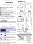
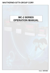
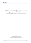
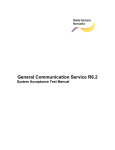
Programmable Temperature Controller
DTC-P Series User Manual
2: Ordering informaiton
DTC
P
1
Please read this manual carefully and keep this manual for future
use
General Specifications
DTC-P series programmable temperature controller, 4 digits LED display, with bar
graphic display, 0.2% accuracy, 0.1 resolution for thermocouple and Pt100 input signal,
0.001 resolution for analong input signal, auto/manual control bumpless transfer
Maximum 4 different programs, each program with 8 segments, 4 program can be
linked together as 1 program with 32 segments
Maximum output power is configurable for each segment
System time unit is switchable bewtee hour, minute and second
Easy monitoring on current runing segment and program excution time period The
program can start from process value or from 0
The program can be triggered or terminated by front key or start running automatically
after power on and controller has the power failure restore function When program
finished, controller can repeat the preset program again or stop operating completely
Guaranteed soak function
segment ending alarm», program ending alarm, program running alarm
segment ending alarm delay function
RS-485 optional, master/slave communicaiton mode optional
Please make sure the wiring is correct before power on, the wiring diagram is
on the size of the controller for easy reference duing the wiring, make sure you
are clear on the output type whether it is Relay, SSR drive or 4-20mA
Controller can switch freely between thermocouple or RTD input signals
for analog inputs, need to specify before order
The factory default control action is OUT1 for reverse control(heating)
customer can set OUT1 as direct control(cooling)
Factory default control mode is P.I.D mode
When I=0,d=0, the control mode set as time proportional mode,proportaional
value is rSt1, control cycle is Cyt1, the output decrease when rSt1 decrease
under heating mode the output increase when rSt1 decrease under cooling
control mode
2
3
4
5
6
7
8
1:Size Information
48 :
49 :
72 :
96 :
94 :
48mm(Width)*48mm(Height)
48mm(Width)*96mm(Height)
72mm(Width)*72mm(Height)
96mm(Width)*96mm(Height)
96mm(Width)*48mm(Height)
2:Version Code
P:
Programmable temperature controller
also known as Ramp and soak controller
3:Output
R:
V:
D:
2:
Relay
SSR drive
4-20mA
0-20mA
5:
6:
7:
0-5VDC
0-10VDC
1-5VDC
4:Alarm options
1:
2:
3:
1 alarm
2 alarms
3 alarms
5:Power supply
96:
85~265VAC
6:Re-transmission
N:
P42:
P005:
P010:
S42:
S005:
S010:
Without re-transmission
PV re-transmission as 4-20mA
PV re-transmission as 0-5VDC
PV re-transmission as 0-10VDC
SV re-transmission as 4-20mA
SV re-transmission as 0-5VDC
SV re-transmission as 0-10VDC
7:Communication
N:
K:
Without communication
RS-485 Modbus RTU
8:Auxiliary Power supply
N: Without auxiliary power supply
24 : 24VDC
1: Dimensions
DTC-48-P
(Unit:mm)
DTC-49-P
DTC-94-P
(Unit:mm)
DTC-72-P
DTC-96-P
(Unit:mm)
(Unit:mm)
Remark: not all options are available at the same time. some of
function share the same terminals , so various functions
may create conflicts with each other, consult our sales
team before order
1
DTC-P Series User Manual
3: Wiring diagram
5 SETTING
DTC-49-P DTC-94-P DTC-96-P
DTC-48-P
1
VDC,
mA
RS485
2
ANL4/ANL3 IN
B-
AL2
DA1-
L
AC85~265V
5.
1 Goes to different programming level
Power on
11
PV
TRS
Power on
SV
Initiating
12
N
NO
PV
AL1
3
DA1TRS
B
NC
4
DA1+
NO
DA1
DTC-72-P
DA1-
15
BRS485
14
Press SET once
16
+24V
VDC/mA
7
18
8
VDC/
mA
9
ANL4/ANL3 IN
OUT1
RTD
B
mA,
V
Current
Voltage
SSR
NC
17
19
10
DA1
AL3
20
A
Remark:
The wiring diagram is for standard products
please refer to the wiring diagram on the unit during
field installation refer to wiring diagram on the unit for
SCR output type
20
21
DTC-59-P
7
6
8
9
10
11
B
A
RTD
13
AN3/
AN4
14
15
AL3
TRS
24V
5V
16
17
AL2
18
19
20
21
A+
22
23
N
OUT1
AL1
RS-485
5
4
3
TC,
mV
B
12
B-
Symbol
Input signal S
Range 1600
E
E
300.
0 C
600 C
K
1300
T
C
R
L
OUT1 OUT2
20
AT
30
5
AL1
40
AL2
50
AL3
60
MAN
70
80
COM
90
PRO
100
A/
M
6
7
8
9
B
C 400.
0 C 1700 C 1800 C
AL1
AL2
50
AL3
60
70
MAN
80
COM
PRO
90
100
Pt100
-200~ 800 C
For example, change AL1 from 0 to 200 0C
(
2)
Change AL1 value
(
3)Parameter setting mode
PV
PV
SV
SV
SV
Press shift
key to
the hundreds’ digits
Press increase key to
set the value to 200
6.
1 Programming level 1
OUT 1: Output 1 indicator
OUT2: Output 2 indicator
6.
1.
1 General parameter under programming level 1
AT: Auto-tuning indicator
Al1: Alarm 1 indicator
AL2:Alarm 2 indicator
Al3: Alarm 3 indicator
Man: manual control indicator
COM: communication indicator
PRG: Programm excecution indicator
Bar Graphic display
SET key
A/M, auto/manual control switch key
Shift key(function key)
Decrease, program pause key
Increase, program active key
Press SET key for 5
seconds to save the
configuration controller
back to PV/SV mode
PV
Below parameter only for master controller
not available on slave controller
PV/SV mode
SV
PV
SV
PV
SV
When communication
mode is master/slave
mode,Rate indicates the
slave controller number
PV
SV
10
OUT2
20
AT
30
AL1
40
AL2
50
AL3
60
70
MAN
80
COM
PRO
90
100
PV
SV
SV
#1 alarm value
or assign a segment to
proceed segment end alarm
PV
SV
#2 alarm value
or assign a segment to
proceed segment end alarm
PV
PV
#2 alarm value
or assign a segment to
proceed segment end alarm
Monitoring the program and
segment number which being
executed
Monitoring how long did the
program has been executed
under current segment
t-H means timing units : Hour
t-M means timing units: Minute
t-S means timing units: Seconds
Parameter access
authorization code
=0, no access to below parameters
=1, can access but can not change parameter value
=2, can access and configure below parameters
*
*
* Choose certain program for field application
PV
SV
PV
OUT1
Auto-tuning switch
no or YES
PV
SV
OUT%
A/
M
Press SET once to goes to programming level 1
SV
‘End’ and ‘PV’ flashes
each other based on 1 sec
interval means program
ending
40
2000 C
SV
Status when program ends
AT
Wu3_Re25
PV
SV
30
N
1300 C
2-10VDC 0-10VDC
Pt100
1-5VDC 0-5VDC 0-50mV 0-20mV
-199.
9~ 200.
0C
4-20mA 0-20mA
PV,indicate process value
SV,indicate setting value
Program jumping(JUMP): Press increse/Run key and SET key at the same time
during the program is running, the program goes to next
segment(Jump to next segment)
Program reset(RESET): Press decrease key and SET key at the same time, the
program reset and PRO indicator went black out
20
C
Programming Level
6.
Program active(RUN): Press increase key for 3 second to active the program
check PRO indicator, when it is flashing, prgram activated
confirmed
Program pause(HOLD): Press decrease/HOLD key for more than 3 seconds during
program is runningto put the program on hold status,PRO
indicator stop flahsing and keep lighting
10
J
800
Remark
Press decrease or increase once the value will increase or decrease by 1
*the value will decrease or increase continuously if keep pressing up or down key
A/M key can be used to save the configuration made to different parameters
Press once can save the modification and exit from the menu
Press SET key for more than 3 seconds can save and exit from parameter menu no matter where you are
Operation key description
OUT1 OUT2
SV low limits
PV/SV mode
J
400.
0 C
PV
OUT%
SV high limits
SV
PV
When upper display
shows Al1 Press key
once to enter into setting mode
flashing digits means configurable
24
Panel discription
10
K
400.
0 C
SET
Programming level 3
(
1)Goes to AL1 parameter
4: Panel discription
OUT%
Symbol
Input signal
Range
Units and signal
Programming level 2
5.
2 Change AL1 value
2
AC85~ 265V
1
Input signal
PV
SET
SET LCK=0101
Press SET for 3 seconds
18
TC,
mV
19
DA1
B
NO
PV
SET
Programming level 1
Press SET for 3 seconds
ANL4/ANL3 IN
17
1.1.28
SV
NO
16
Controller goes back to PV/SV mode
if there is no key pad inputs for more than 1 minutes
PV/SV mode
15
A
AL3
6
TRS
SV
RS485
5
Edition code
Display change automatically
13
NC
SV
=1, use #1 program(8 segments)
=2, use #2 program(8 segments)
=3, use #3 program(8 segments)
=4, use #4 program(8 segments)
=5, use #1+#2 program(16 segments)
=6, use #3+#4 program(16 segments)
=7, use #1+#2+#3 program(24 segments)
=8, use #1+#2+#3+#4 program(32 segments)
Parameter menu for different program
=1,parameter menu for #1 program
=2,parameter menu for #2 program
=3,parameter menu for #3 program
=4,parameter menu for #4 program
Commnication
address
To next page
2
DTC-P Series User Manual
From previous
page
PV
SV
PV
Access to parameter
menu for #1 program
PV
SV
PV
SV for #1 segment
of #1 program
PV
PV
PV
Maximum output ratio for #1
segment of #1 program
PV
PV
Maximum output ratio for #2
segment of #1 program
Time for #2 segment of #2 program
0.0-999.9 hours or minutes
0-9999 seconds
PV
PV
PV
PV
PV
PV
PV
PV
PV
Time for #5 segment of #2 program
0.0-999.9 hours or minutes
0-9999 seconds
Time for #5 segment of #1 program
0.0-999.9 hours or minutes
0-9999 seconds
PV
PV
PV
SV for #6 segment
of #1 program
PV
PV
Time for #6 segment of #1 program
0.0-999.9 hours or minutes
0-9999 seconds
Maximum output ratio for #6
segment of #1 program
PV
PV
Maximum output ratio for #5
segment of #2 program
Maximum output ratio for #5
segment of #1 program
PV
SV for #6 segment
of #2 program
Time for #6 segment of #2 program
0.0-999.9 hours or minutes
0-9999 seconds
Maximum output ratio for #6
segment of #2 program
PV
PV
PV
PV
PV
PV
Time for #8 segment of #1 program
0.0-999.9 hours or minutes
0-9999 seconds
PV
PV
Maximum output ratio for #8
segment of #1 program
PV/SV mode
PV
Maximum output ratio for #7
segment of #2 program
SV for #8 segment
of #1 program
PV
SV
SV for #8 segment
of #2 program
Time for #8 segment of #2 program
0.0-999.9 hours or minutes
0-9999 seconds
Maximum output ratio for #8
segment of #2 program
PV/SV mode
Maximum output ratio for #2
segment of #4 program
SV for #3 segment
of #4 program
Time for #3 segment of #4 program
0.0-999.9 hours or minutes
0-9999 seconds
Maximum output ratio for #3
segment of #4 program
PV
PV
SV for #5 segment
of #3 program
Time for #5 segment of #3 program
0.0-999.9 hours or minutes
0-9999 seconds
Maximum output ratio for #5
segment of #3 program
SV for #6 segment
of #3 program
PV
PV
PV
PV
Time for #4 segment of #4 program
0.0-999.9 hours or minutes
0-9999 seconds
Maximum output ratio for #4
segment of #4 program
SV for #5 segment
of #4 program
Time for #5 segment of #4 program
0.0-999.9 hours or minutes
0-9999 seconds
Maximum output ratio for #5
segment of #4 program
PV
SV for #6 segment
of #4 program
PV
Time for #6 segment of #4 program
0.0-999.9 hours or minutes
0-9999 seconds
PV
SV for #7 segment
of #3 program
Time for #7 segment of #3 program
0.0-999.9 hours or minutes
0-9999 seconds
Maximum output ratio for #7
segment of #3 program
SV for #8 segment
of #3 program
Time for #8 segment of #3 program
0.0-999.9 hours or minutes
0-9999 seconds
PV
Maximum output ratio for #6
segment of #4 program
PV
SV for #7 segment
of #4 program
PV
Time for #7 segment of #4 program
0.0-999.9 hours or minutes
0-9999 seconds
PV
Maximum output ratio for #7
segment of #4 program
PV
SV for #8 segment
of #4 program
PV
Time for #8 segment of #4 program
0.0-999.9 hours or minutes
0-9999 seconds
PV
Maximum output ratio for #8
segment of #3 program
PV
SV for #4 segment
of #4 program
PV
Maximum output ratio for #6
segment of #3 program
PV
PV
PV
PV
PV
Time for #7 segment of #2 program
0.0-999.9 hours or minutes
0-9999 seconds
Maximum output ratio for #7
segment of #1 program
Time for #2 segment of #4 program
0.0-999.9 hours or minutes
0-9999 seconds
Time for #6 segment of #3 program
0.0-999.9 hours or minutes
0-9999 seconds
PV
PV
Time for #7 segment of #1 program
0.0-999.9 hours or minutes
0-9999 seconds
PV
PV
PV
SV for #7 segment
of #2 program
SV for #7 segment
of #1 program
PV
PV
Maximum output ratio for #1
segment of #4 program
SV for #2 segment
of #4 program
Maximum output ratio for #4
segment of #3 program
SV for #5 segment
of #2 program
Time for #1 segment of #4 program
0.0-999.9 hours or minutes
0-9999 seconds
PV
PV
PV
SV for #1 segment
of #4 program
PV
Time for #4 segment of #3 program
0.0-999.9 hours or minutes
0-9999 seconds
Maximum output ratio for #4
segment of #2 program
Access to parameter
menu for #4 program
PV
PV
PV
PV
SV for #4 segment
of #3 program
Time for #4 segment of #2 program
0.0-999.9 hours or minutes
0-9999 seconds
SV for #5 segment
of #1 program
Maximum output ratio for #2
segment of #3 program
PV
PV
Maximum output ratio for #4
segment of #1 program
Time for #2 segment of #3 program
0.0-999.9 hours or minutes
0-9999 seconds
PV
Maximum output ratio for #3
segment of #3 program
SV for #4 segment
of #2 program
Time for #4 segment of #1 program
0.0-999.9 hours or minutes
0-9999 seconds
SV for #2 segment
of #3 program
PV
PV
PV
Maximum output ratio for #1
segment of #3 program
PV
Time for #3 segment of #3 program
0.0-999.9 hours or minutes
0-9999 seconds
Maximum output ratio for #3
segment of #2 program
SV for #4 segment
of #1 program
Time for #1 segment of #3 program
0.0-999.9 hours or minutes
0-9999 seconds
PV
PV
PV
SV for #1 segment
of #3 program
SV
SV for #3 segment
of #3 program
Time for #3 segment of #2 program
0.0-999.9 hours or minutes
0-9999 seconds
Maximum output ratio for #3
segment of #1 program
PV
Access to parameter
menu for #3 program
PV
SV for #3 segment
of #2 program
Time for #3 segment of #1 program
0.0-999.9 hours or minutes
0-9999 seconds
PV
PV
Maximum output ratio for #2
segment of #2 program
PV
PV
SV
PV
SV for #2 segment
of #2 program
SV for #3 segment
of #1 program
PV
PV
PV
PV
PV
PV
Maximum output ratio for #1
segment of #2 program
Time for #2 segment of #1 program
0.0-999.9 hours or minutes
0-9999 seconds
PV
PV
Time for #1 segment of #2 program
0.0-999.9 hours or minutes
0-9999 seconds
SV for #2 segment
of #1 program
PV
SV
SV for #1 segment
of #2 program
Time for #1 segment of #1 program
0.0-999.9 hours or minutes
0-9999 seconds
PV
PV
PV
Access to parameter
menu for #2 program
PV/SV mode
SV
This controller can have maximum 4 programs, and user can choose to run certain program
different programs can be linked together using PLNK parameter, linked program with 16,24, or 32 segments
Maximum output ratio for #8
segment of #4 program
PV
PV/SV mode
SV
3
DTC-P Series User Manual
6.
2 Typical application
Suppose we need a program with 5 segments, using #1 program for the application, check below curve, the maximum output ratio restricted to 80% at segment 4 to
avoid damage.
system timing unit: hours
SV
Temperature
300
Dwell
300
Ramp
Ramp
Segment 2
Ramp
220
Dwell
Segment 3
250
220
Segment 5
Segment 4
Segment 1
0
Time
0.5 hour
1 hour
How to create a program like above figure
0.7 hour
1.5 hour
0.3 hour
PV
PV/SV mode
SV
Press SET until
you see PLCK
PV
PV
SV
PV
SV
SV
SET PLNK=1 to use the #1 program for
the application
SET PLCK=2 to access to program
configuration menu
SET PSEL=1 goes to parameter menu
for #1 program
PV
SV
Set the SV for #1 segment at 300C
PV
PV
PV
PV
SV
SV
SV
SV
Set the ramp time for #1 segment at 1 hour
Maximum output for #1 segment is 100%
Set the SV for #2 segment at 300
Dwell time for #2 segment at 0.5 hour
PV
PV
PV
PV
SV
SV
SV
SV
Maximum output for #2 segment is 100%
Set the SV for #3 segment at 220 C
Ramp time for #3 segment is 0.7 hour
Maximum output for #3 segment is 100%
PV
PV
PV
PV
SV
SV
SV
SV
Set the SV for #4 segment at 220 C
Dwell time for #4 segment at 1.5 hour
PV
PV
SV
PV
PV
SV
Ramp time for #5 segment is 0.3 hour
SV
Maximum output for #5 segment is 100%
Press SET key for 3 seconds
or light press A/M key to save
the configuration and exit from
the programing menu
SV
SET maximum output as 0.0% for #6 segment
Maximum output for #4 segment is 80%
SET SV as any random value for #6 segment
Set the SV for #5 segment at 250 C
PV
SV
SET any random value for time of #6 segment
PV
SV
PV/SV mode
6.
3 Program automatically terminated
SET the maximum output menu as 0.0% at certain segment if a program less than 8 segments
and program ending when it comes to the last segment. in above case, the program only have 5 segments, then set the maximum output for #6 segment as 0.0%,
program ends after 5 segments.
6.
4 Program automatically jumping
If a program needs to skip on certain segments, set the segment time as 0.0, when program runs to the segment where the time has been set as 0.0, it will go to
next segment automatically, for example, in a program where we want to skip on segment 4, then SET the time for segment 4 as “0.0", then program automatically
goes to segment 5 from segment 3.
4
DTC-P Series User Manual
Parameter
Notation
6.
2 Programming level 2
A/
M
Refer to right figure, press SET key for 3 seconds to
enter into programming level 2, below parameter shows one by
one on the fixed sequence
Parameter
Notation
Parameter
description
Proportional
band for out1
Default
value
Range
0.
0~200.
0
Sec
Sec
Auto tuning offset
value(AtVL)
C
Control cycle time
0 to 999 Sec
for out 1
0.
0 to 100.
0
Control
Hysteresis
For out1
Proportional
reset
For out1
Output lower limit
Output higher limit
Proportional band for output 1(SEP P=3.0 for analog input signal)
unit is degree, when P1=0, controller works as ON/OFF controller
30 to 30
Integral time for output 1, when I1=0, integral action disabled
integral action gets more sensitive when I1 gets bigger, but fluctation is more expected
Derivative time for out 1, when d1=0, the derivative action disabled
derivative action gets more sensitive when d1gets bigger, but fluctation is more expected
210
30
0
Set ATVL to prevent overshoot occurred
during autotuning process.
20
Control cycle time for out 1
Set as 20 S for relay output, 2 S for SSR drive output
2.
0
When P1=0.0, OUT1 is on/off control
In heating application
PV >SV OUT1 terminated
PV<SV-HYS1 OUT1 activated
In cooling application:
PV>SV+HYS1 OUT1 activated
PV<SV OUT1 terminated
5.
0
0.
0 to 100.
0%
0.
0 to 100.
0%
00000255
Proportional reset for overshoot protection
only for out1 output.(Auto set after auto-tun
ing)
0.
0
Code
N
0,
1
1
0: Program starts to run from 0
1: Program starts to run from process value
Communication address
0127
1
To configure the address of controller in communication mode
Communication rate
0,
1,
2,
3
2
bAUd=0 Rate=2.4K
bAUd=1 Rate=4.8K
00: No alarm output
01: Deviation high alarm with alarm standby funciton
02: Deviation low alarm with alarm standby function
03: Deviation high/low alarm with alarm standby function
04: Deviation band alarm with alarm standby function
05: Process high alarm with alarm standby function
06: Process low alarm with alarm standby function
07: Segment ending alarm
ALD
□
Specification(Example for alarm 1)
No alarm
10 or 00
Deviation high alarm
AH1 Alarm ON
AL1≥0
100.
0 To set the output higher limit for out 1
A
LCK=0000: all parameters are configurable
LOW
HIGH
SV+AL1
SV
11
Deviation high alarm
LCK=0001: only SV value configurable
Access
protection
parameter
bAUd=2 Rate=9.6K
bAUd=3 Rate=19.2K
Alarm mode specification
To set the output lower limit for out 1
0
Remark
Temperature where
the program starts
to run
Alarm mode(ALd=00~18)
**
10: No alarm output
11: Deviation high alarm
12: Deviation low alarm
13: Deviation high/low alarm
14: Deviation band alarm
15: Process high alarm
16: Process low alarm
17: Program execution alarm
18:Program ending alarm
6.
3.
2
Default
value
Range
Remark
20.
0
Integral time for
out 1
Derivative time
for out 1
Parameter
description
PrF
AL1<0
LCK=0010: configurable on SV and parameters under programming level 1
Alarm ON
AH1
LCK=0011: can not configure all parameters
LOW
LCK=0101:all parameters are configurable, accessible to programming level 3
SV+AL1
LCK=0201:all parameters are configurable, accessible to programming level 4
HIGH
SV
Deviation low alarm
Alarm ON
6.
3 Programming level 3
AL1≥0
A/
M
LOW
6.
3.
1 How to access to programming level 3
1. Refer to 6.2 instruction and goes to programming level 2,
SET LCK=0101 and press SET for 3 seconds to exit to PV/SV mode
2.Refer to figure at right, Press SET and shift key at the same time for 3 seconds to access to programming level 3
below parameters will show one by one based on below sequence
Parameter
Notation
Parameter
Range
description
Input signal selection
Default
value
B
LOW
Range
400.
0 C
1300
C
J
E
E
300.
0 C
600 C
K
J
400.
0 C
800
C
N
Wu3_
Re25
HIGH
SV
1300 C
2000 C
Alarm ON AH1
13
SV-AL1
LOW
Input signal
notation
AH1
SV
Alarm ON
HIGH
SV+AL1
Deviation band alarm
S
Description
Range
SV+AL1
Deviation high/low alarm
C
K
Deviation low alarm
AH1
Remark
Input signal
notation
Description
Alarm ON
AL1<0
HIGH
SV+AL1
SV
12
AH1
T
R
B
1600 C 400.
0 C 1700 C 1800 C
2-10VDC 0-10VDC
Pt100
1-5VDC 0-5VDC 0-50mV 0-20mV
-199.
9~ 200.
0C
4-20mA 0-20mA
Pt100
-200~ 800 C
D
LOW
Remark 1: User can select thermocouple or Pt100 via front key
Remark 2: Analog input has to be specified before order except 0-20mV and 0-50mV
Decimal point
for analog input
SV lower limit
0 1,
,2,
3
0
0: No decimal point
3: 3 decimal point
-1999 to 9999
0
Setting value lower limit
Or to define the lower limit temperature for Re-transmission function
400
0 1,
,2
0
PV Bias value
199 to 199
0.
0
To compensate the measuring error from the sensors
Sampling rate
0 to 30
25
When value gets smaller, the response to the sensor is more sensitive
but can expect some fluctuation, when value gets bigger, it will have reverse effects
Analog input
lower limit display value
-199~9999
0
For example, the display value is ANL1 when
input is 4mA for 4-20mA range
2000
For example, the display value is ANH1 when
input is 20mA for 4-20mA range
11
To define the alarm mode for #1 alarm
refer to alarm mode figure for alarm mode description
1.
0
Alarm hysteresis value for #1 alarm
High alarm(lower side hysteresis)
Low alarm(higher side hysteresis)
10
To define the alarm mode for #2 alarm
refer to alarm mode figure for alarm mode description
Alarm hysteresis 0.
0 to 100.
0
for #2 alarm
1.
0
Alarm hysteresis value for #2 alarm
High alarm(lower side hysteresis)
Low alarm(higher side hysteresis)
Alarm mode for
#3 alarm
10
To define the alarm mode for #3 alarm
refer to alarm mode figure for alarm mode description
1.
0
Alarm hysteresis value for #3 alarm
High alarm(lower side hysteresis)
Low alarm(higher side hysteresis)
Display unit
Analog input
-1999~9999
higher limit display value
Alarm mode for
#1 alarm
00 to 18
Alarm hysteresis
0.
0 to 100.
0
for #1 alarm
Alarm mode for
#2 alarm
00 to 18
00 to 18
Alarm hysteresis 0.
0 to 100.
0
for #3 alarm
Control action
0 or 1
0
ALt
Program ending
alarm delay time
09999
Seconds
0
Wait
0.
0-100.
0
Celcius
PUNt
System time units
0,
1,
2
0
SV-AL1
HIGH
SV
SV+AL1
Process high alarm
1: 1 decimal point 2: 2 decimal point
only applicable for analog input
-1999 to 9999
SV higher limit
Alarm ON
14
H
AH1
15
LOW
Alarm ON
HIGH
AL1
Setting value higher limit
Or to define the higher limit temperature for Re-transmission function
0: Celcius
1: Fahrenheit
2: Without Unit
Process low alarm
Alarm ON
J
AH1
16
LOW
HIGH
AL1
Deviation high alarm with hold action
AH1 Alarm ON
AL1≥0
LOW
E
HIGH
SV+AL1
SV
01
Deviation high alarm with hold action
AL1<0
AH1
LOW
Alarm ON
SV+AL1
HIGH
SV
Deviation low alarm with hold action
Alarm ON
AL1≥0
LOW
F
SV+AL1
SV
02
AH1
HIGH
Deviation low alarm with hold action
Alarm ON
AL1<0
LOW
AH1
SV+AL1
SV
HIGH
Deviation high/low alarm with hold action
0:Reverse control(heating)
1:Direct control(cooling)
0:
When value=0, the alarm output right after program end
Other value from 1-9999 seconds
Program end alarm output delay certain (from 1-9999 seconds) then output
0:Disable program holding function
Other value: temperature range to active the program holding function
G
0: Hour (0.0~999.9 Hour)
1: Minutes(0.0~999.9 Minutes)
2: Second(0-9999 Seconds)
M
Alarm ON AH1
03
LOW
SV-AL1
AH1
SV
Alarm ON
SV+AL1
HIGH
Deviation band alarm with hold action
Alarm ON
04
LOW
SV-AL1
SV
HIGH
SV+AL1
5
DTC-P Series User Manual
8.
AUTO-TUNING
Specification(Take alarm 1 as example)
Code
Process high alarm with hold action
05
K
Auto-tuning parameter
Alarm ON
AH1
LOW
AL1
Press SET key for
3 seconds to save
and active
auto-tuning
SET
HIGH
Process low alarm with hold action
Alarm ON
06
L
Press , SET the value
as “YES”
Press SET for 3 seconds, goes to
programming level 1
AH1
Master controller: the SV value for the auto-tuning process is the SV for the first segment
LOW
2
HIGH
AL1
Slave controller: the auto-tuning for the slave controller must be activated after the master
controller, the setting value is related to master controller
Segment ending alarm
3
17
Program execution alarm
4
18
Program ending alarm
9.
Master and Slave Communication Mode
Remark: “Alarm standby” function means if the alarm condition meets while
controller just power on the alarm will not output, when temperature goes out to
the alarm range and falls back to alarm range again, the alarm will output
Alarm mode apply to all three alarms, alarm 1, alarm 2 and alarm 3.
Various alarm for program control
9.
1 Master controller: Act as master controller to control slave controller
9.
2 Slave controller: controlled by master controller, the SV value was given by
master controller
SV and Rate parameter for slave controller
SV for slave controller, SV=(Rate 9999) X SV of master controller
Segment ending alarm: When ALd=07, the alarm is defined as segment ends alarm
AL(AL1 ,AL2, Al3) value means when program comes to the certain segment, the alarm will output
For example, When ALd1=07, AL1=2(or 0.2), means when program finish segment 2. the alarm
will go off and remind operator that the segment 2 is finished.
900
A/
M
TrSF
Re-transmission
setting
PCrL
Master/Slave
communication
mode configuration
0
Analog output
configuration
AUtO
Auto/manual
control configuration
1
0
1
Define controller as slave controller
Define controller as master controller
0
Define analog output as re-transmission output
Define analog output as PID control output
AUTO=0 Disable auto/manual switch
AUTO=1 Enable auto/manual switch
SV1.
1=1000
tr1.
1=10.
0
ot1.
1=100.
0%
SV
Time
10 hours
1
0
Slave 2
SV
Time
Re-transmission on the process value
Re-transmission on the setting value
0
B-
(Slave)
Slave 1
SV
Factory
Remark
default
0
ConF=0 Turn off communication
ConF=1 Turn on communication
ConF=2 Turn on Master/Slave communication mode
0,
1,
2
Communication
function setting
A+
800
Master
1. Follow instruction in 6.2 to goes to programming level 2, change
LCK value to 0201 then press SET key for 3 seconds to save the change
2. Refer to image at right, Press SET and
at the same time for 3 seconds
to goes to programming level 4, below parameter will display one by one
Range
B-
(Slave)
1000
6.
4.
1 How to access to programming level 4
Parameter
description
ConF
A+
SV for master and slave controller
Program execution alarm, When ALd01=18, the alarm will go off when program starts
Parameter
Notation
B-
(Master)
Program ending alarm, When ALd01=17, the alarm is defined as program ends alarm,
When program ends, the alarm will go off.
6.
4 Programming level 4
A+
Time
10 hours
10 hours
SV for slave 1 is 900
SV for slave 2 is 800
10.
RS485 Communication
(1) Support Modbus-RTU protocol, support 03 read command, 06 and 10 write
command
(2) Communication mode: single-master Rs485 asynchronous serial
communication baud rate: 2400, 4800,9600,19200(9600 baud rate is factory
default value)
(3)The maximum write command for the controller is 36 at once, maximum read
command is 37 at once for the read command
Program resets right after power on, press start
key to active the program manually.
How programs
starts to run after
power on and
after power failure
0
1
Program starts to run at the point before power
cut off( apply in power failure situation)
Program resets right after power on then
runs the program automatically
0
2
PrEP=0 Program doesn’t repeat after program ends
PrEP=1 Program repeat from segment 1 after one
complete circle
PrEP
Program repeat
mode configuration
0 1
0
7: Panel discription
Manual control works only after the program starts to run
All controllers except 48mm*48mm with auto/manual A/M transfer key
Example: Following is an example of manual setting to 70% output.
Auto control mode
Manual setting mode
Manual control mode
Press A/M
key for 3
seconds
OUT1 OUT2
OUT%
10
20
AT
30
AL1
40
AL2
50
AL3
60
70
MAN
80
COM
PRO
90
100
A/M
MAN lamp is turns
off in Auto control
mode.
OUT1 OUT2
OUT%
10
20
AT
30
AL1
40
AL2
50
AL3
60
70
MAN
COM
PRO
80
90
100
A/M
Press A/M key for 3 seconds
to manual setting mode. In
manual setting mode, MAN
lamp light up, The digit which
flashing is settable.
OUT1 OUT2
OUT%
10
20
AT
30
AL1
40
AL2
50
AL3
60
70
MAN
COM
PRO
80
90
100
A/M
Pressing the UP key
increase numerals,
and pressing the DOWN
key decrease numerals.
Press SET key after set
value to 70.0.
11.
Input Ranges
Input type
to
to
to
to
K2
to
to
E1
to
to
to
E2
to
to
J1
to
to
to
J2
to
0.
0 to
T
0.
0 to
S
to
** 0
to
0
R
200 to
B
to
0
N
Wu3_Re25
60 0 to
K1
0.
0
0.
0
0
0
0
0.
0
0.
0
0
0
0
0.
0
0.
0
0
0
0
Input type
Code
200.
0
400.
0
400
600
1300
200.
0
300.
0
200
400
600
300.
0
400.
0
300
400
800
300.
0
400.
0
1600
1700
1800
1300
2000
2
2
K
K
K
3
3
D2
D4
A4
A6
B3
D2
D3
E
E
E
1
1
J
J
J
T
T
A2
A4
A6
D3
D4
A3
A4
A8
S
R
B
N
W
D3
D4
B6
B7
B8
B3
B0
Code
100
200
400
800
200
400
600
800
0
0
0
0
100
200
200
200
P
P
P
P
P
D
D
D
D
D
D
D
D
Input type
AN1
AN2
AN3
AN3
AN4
AN4
AN4
AN3
AN3
06
07
08
13
02
A1
A2
A4
A8
C2
C4
C6
C8
Code
-1999 to 9999
-199.
9to 999.
9
-19.
99to 99.
99
-1.
999to 9.
999
Remark: when input signal is S thermocouple, the accuracy is not guaranteed at
range 0-100 celcius
1: User can select thermocouple and Pt100 using front key
2:Analog input signal has to be specified before order expect 0-20mA and 0-50mA
**In manual control mode ,press A/M key for 3 seconds to auto control mode.
** Power-on Manual function can be selected. Pko in level2 for initial output value.
**A/M key can also be used for SAVE and EXIT key.
DTC-P Series User Manual