1
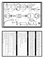
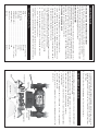
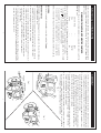
BENCH GRINDER
MODEL CBG6RZ
OPERATING & MAINTENANCE
INSTRUCTIONS
0100
9
Thank you for purchasing this CLARKE BENCH GRINDER.
Before attempting to operate this machine, please read this instruction manual
thoroughly and follow all directions carefully. By doing so you will ensure the safety
of both yourself and others around you, and at the same time, you should look
forward to long and trouble free service from your Bench Grinder.
GUARANTEE
PAGE
This product is guaranteed against faults in manufacture for 12 months from
purchase date. Keep your receipt as proof of purchase. This guarantee is invalid
if the product has been found to have been abused in any way, or not used for the
purpose for which it was intended, or to have been tampered with in any way. The
reason for return must be clearly stated. This guarantee does not affect your
statutory rights.
CONTENTS
Guarantee, General Safety Rules ......................................................... 2
Special Safety Rules for Grinders ........................................................... 3
Pre Assembly Check ............................................................................... 4
Electrical Connections, Fuse Rating ..................................................... 5
Assembly, (Eyeshield and Toolrest) ....................................................... 6
Maintenance (incl. changing the grinding wheel) ............................ 7
Technical data ........................................................................................ 7
Parts List and Diagram ............................................................................ 8
6.
5.
4.
3.
2.
1.
DO NOT FORCE YOUR BENCH GRINDER. It will do a better and safer job if used
at the rate for which it was designed.
MAKE YOUR WORKSHOP CHILDPROOF with padlocks, master switches, or by
removing starter keys.
KEEP CHILDREN AWAY. All visitors, but in particular children, should be kept at
a safe distance away from the work area.
DO NOT USE IN A DANGEROUS ENVIRONMENT. Do not use any power tools in
damp or wet areas, or expose them to rain. Keep work area well lit.
KEEP WORK AREA CLEAN. Cluttered areas and work benches invite
accidents.
REMOVE ADJUSTING KEYS AND WRENCHES. Make a habit of checking to see
that all adjusting keys and wrenches are removed from the machine before
turning it on.
KEEP GUARDS IN PLACE and check they are not damaged.
GENERAL SAFETY RULES
7.
2
9.
8.
WEAR THE PROPER APPAREL. No loose clothing, gloves, neckties, rings,
bracelets, or any other jewellery which might get caught in moving parts.
Non-slip footwear is recommended. Wear protective hair covering to contain
long hair.
USE THE RIGHT TOOL. Do not force your tool or attachment to do a job for
which it was not designed.
10. ALWAYS USE SAFETY GLASSES. Everyday glasses only have impact resistant
lenses, they are not safety glasses. Also use a face mask if grinding operation
is generating a lot of dust.
11. DO NOT OVERREACH. Keep a firm footing and proper balance at all times.
12. DISCONNECT FROM THE MAINS before attempting any kind of service work or
adjustment or when changing accessories such as grinding wheels.
13. MAINTAIN TOOLS WITH CARE. Keep tools sharp and clean for best and safest
performance.
14. REDUCE THE RISK OF UNINTENTIONAL STARTING. Make sure switch is in the OFF
position before plugging in.
15. CHECK FOR DAMAGED PARTS. Before further use of tool, any damaged part
should be carefully inspected and checked to determine that it will operate
properly and perform its intended function. Check for alignment of moving
parts, binding of moving parts, mounting, and any other damage that may
affect its operation. A guard or other part that is damaged should be properly
repaired or replaced. If in any doubt contact your local dealer.
2 Washer
1 Bolt
No. Description
HT6481902
HT6481901
Part No.
22 Spring Washer
21 Screw
20 Capacitor
No. Description
3040582
3040528
HT6481920
Part No.
PARTS LIST & DIAGRAM
3 Outer Protection Cover LH HT6481903
7B Grinding Wheel (Fine)
5 Wheel Flange
4A Wheel lock nut RH
4 Wheel lock nut LH
6501135
7A Grinding Wheel (Medium) 6501089
7 Grinding Wheel (Coarse)
HT6481908
6501088
HT6481905
29 Rotor /Shaft
28 Main Body End Cover
27 Bearing
26 Spring Washer
25 Screw
HT6481904A 24A Tool Rest RH
HT6481904
30 Stator/Body
HT6481932
HT6481930
HT6481929
HT6481928
HT6481927
HT6481926
HT6481925
3044576
8 Middle Ring
HT6481909
32 Base
3A Outer Protection Cover RH HT6481903A 23 Flat Washer
9 Screw
HT6481910
HT6481933
Replace a cracked wheel immediately.
15 Eye Shield
14 Eye Shield Bracket
HT6481915
HT6481914
39 Washer
38 Screw
35 Rubber Foot
11A Inner Protection Cover RH HT6481911A 34 Switch Assy.
HT6481939
HT6481938
HT6481935
HT6481934
HT6481924A
HT6481924
10 Spring Washer
33 Bottom Plate
Always use guards and eyeshield.
HT6481916
HT6481940
24 Tool Rest LH
11 Inner Protection Cover LH HT6481911
1.
16 Spring Washer
40 Capacitor Bracket
SPECIAL SAFETY RULES FOR BENCH GRINDERS
2.
Do not overtighten wheel nut.
HT6481917
HT6481941
3.
17 Nut
41 Washer
4.
HT6481918
Adjust distance between wheel and tool rest to maintain 1/16” (1.6mm) or less
separation as the diameter of the wheel will decrease with use.
18 Power Cable
Use a grinding wheel suitable for the speed of grinder. (See technical data).
HT6481942
5.
Stand slightly to one side of the bench grinder during operation, not facing
directly in front.
For Spare Parts and Servicing,please contact your nearest dealer, or
CLARKE International, on one of the following numbers.
42 Nut
6.
One minute of free rotation is necessary for a new grinding wheel: should the
new grinding wheel be faulty and break, it will happen within the first minute
of operation.
HT6481919
7.
Do not use the grinding wheel for any kind of cutting.
Do not remove the wheel guard except when changing a worn wheel.
19 Cable Clamp
8.
PARTS & SERVICE TEL: 020 8988 7400
PARTS & SERVICE FAX: 020 8558 3622
or e-mail as follows:
PARTS: [email protected]
SERVICE: [email protected]
9.
12. NEVER LEAVE A GRINDER RUNNING UNATTENDED. TURN POWER OFF. Do not
leave tool until it comes to a complete stop.
8
11. Use a file to remove burrs from the grinding wheel.
10. Do not over stress the grinding wheel.
3
MAINTENANCE
(A) EYESHIELD and SPARK ARRESTER BRACKET ADJUSTMENT
The see-through eye shields allow the user to see the operation clearly and to work
precisely. The eye shields can be adjusted up and down to suit operator.
The Spark Arrester brackets should be adjusted so that they are as close as possible
to the wheel without impairing the wheels rotation.
(B) TOOLREST ADJUSTMENT
The appropriate adjustment of the Tool Rests provides the operator with a correct
working angle and a firm and efficient base for working. Adjustments can be
made by loosening the mounting screws and moving the Tool Rest to within 1/16”
(1.6mm) from the wheel. Due to the wear on the grinding wheel, it will be
necessary to adjust the Tool Rests from time to time. Always re-tighten the
mounting screws once adjustment is complete.
(C) CHANGING THE GRINDING WHEEL
2.
1.
Hold the grinding wheel firmly and remove the nut and flange from the shaft,
noting that the left hand wheel nut has a left hand thread.
Slacken the Spark Arrester bracket and Tool Rest mounting screws, and pull
the bracket and Tool Rest away from the wheel.
Switch off and un-plug from mains power supply. Disassemble outer covers,
left or right, by removing the three cover retaining nuts, bolts and washers.
To renew or change the grinding wheels, follow the steps given below.
3.
the paper blotters are in place either side of the wheel.
Take off the used wheel and replace with the new one, ensuring:
that there is a good balanced rotation of the grinding wheel, and
4.
a.
Readjust the Tool Rest and Spark Arrester Brackets as described above.
b.
Switch ON the machine and allow it to rotate freely for at least one minute.
you do not overtighten the wheel nut.
5.
c.
6.
TECHNICAL DATA
MOTOR ........................................................................ 230V ~ 50HZ; 1Ph
SPEED ........................................................................... 2800 RPM
POWER RATING .......................................................... 210Watts
FUSE RATING ............................................................... 5 Amps
WHEEL SIZE .................................................................. 150 x 20 x12.7 mm
GRINDING WHEELS ..................................................... 1 x Fine; 1 x Coarse
WEIGHT (Packed) ....................................................... 9 KG
DUTY CYCLE ................................................................ 5/5 min.
PART NO. ..................................................................... 6500105
7
13. USE ONLY APPROVED REPLACEMENT GRINDING WHEELS. Contact your local
dealer or Clarke International (081-558 6696) for approved replacement
grinding wheels and accessories. The use of inferior accessories may cause
risk of injury.
14. Never use the side of the grinding wheel. Use only the front face.
PRE-ASSEMBLY CHECK
Before assembling your Bench Grinder, please check to ensure that all the parts,
shown below, have been included.
3.
2.
1.
Two Tool rests, each complete with 2 x screws, 2 x spring washers and 2 x flat
washers (C).
Two spark arrestor brackets, each complete with 1 x screw, 1 x spring washer
and 1 x flat washer (B).
Two Eyeshields, each complete with 1 x nut, 1 x bolt, 1 x spring washer and 2
x flat washers (A).
Main Body (switch and power cable with plug are included).
Note: if any parts are missing or damaged, please contact your local dealer or
Clarke International on 081-558 6696 for replacement.
4.
4
ELECTRICAL CONNECTIONS
Connect the mains lead to a standard, 240 volt (50Hz) electrical supply through a
fused good quality (rubber preferred)13 amp BS 1363 plug, or a suitable fused
isolator switch.
WARNING: THIS APPLIANCE MUST BE EARTHED
Blue
Green & Yellow
—-
—-
—Live
Neutral
Earth
IMPORTANT: The wires in the mains lead are coloured in accordance with the
following code:
Brown
As the colours of the flexible cord of this appliance may not correspond with the
coloured markings identifying terminals in your plug, proceed as follows:
Connect GREEN & YELLOW cord to terminal marked with a letter “E” or Earth
symbol ‘ ’ or coloured GREEN or GREEN & YELLOW.
Connect BROWN cord to terminal marked letter “L” or coloured RED.
Connect BLUE cord to terminal marked letter “N” or coloured BLACK.
We recommend that this unit is fitted with a Residual Current Device (RCD).
FUSE RATING
The fuse in the plug for this appliance must be rated at 5 amps.
IMPORTANT NOTICE
4.
3.
2.
1.
Replacement fuse covers can be obtained from your local dealer, an
electrical stockist, or CLARKE INTERNATIONAL Spares Department
(tel. 020 8988 7400).
Should you wish to replace a detachable fuse carrier, ensure that the correct
re-placement is used (as indicated by marking or colour code).
Never use the plug without the fuse cover fitted.
This plug must be thrown away if it is cut from the electric cable. There is a
danger of electric shock if it is subsequently inserted in a socket outlet.
If this appliance is fitted with a plug which is moulded onto the electric cable (i.e.
non rewirable) please note:
5.
The fuse in the plug must be replaced with one of the same rating (see wiring/
electrical connection section in the instruction manual) and this replacement
must be ASTA approved to BS1362.
5
1.
Assemble the Spark Arrester brackets onto the wheel guards, using the screws
and washers provided, in the manner shown in Fig.2.
Fix the Tool Rests, with the screws and washers provided, in the manner shown
in Fig.1. The Tool Rests are adjustable and should be positioned 1/16" (1.6mm)
from the grinding wheels. Ensure that the Tool Rest is firmly fixed and horizontal.
ASSEMBLY
2.
3.
Assemble the Eye Shields on to the Spark Arrester brackets using the nuts, bolts
and washers supplied, in the manner shown in Fig.3. The angle for the Eye
Shields can be adjusted to suit the operator.
NOTE: Before fully tightening the screws, each bracket should be adjusted by
sliding it as close to the grinding wheels as possible, without impairing the
wheels rotation. As the wheel wears down with use, it will be necessary to readjust the Spark Arrester brackets accordingly.
4.
Fig. 2
We recommend that your Clarke Bench Grinder is secured to your workbench
before operation, using the pre-drilled holes in the base. Do not overtighten
the mounting bolts as this could damage the plastic base.
Fig. 1
Fig.3
6