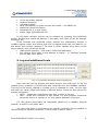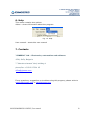
1
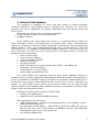
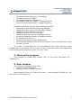
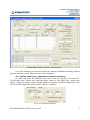
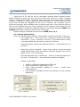
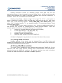
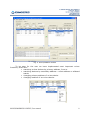
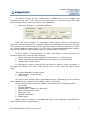
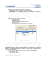
M-BUS/MODBUS CONFIGURATION SOFTWARE FOR GINEERS MMCR-64 USER MANUAL TABLE OF CONTENTS 1. General information 3 2. Starting the program 4 3. Main window 3.1.Setting serial port 3.2.Setting general m-bus flags 3.3. Setting MMCR interfaces 4 5 6 7 4. M-bus and ModBus window 7 5. Log 11 6. Help 12 7. Contacts 12 M-BUS/MODBUS CONFIG, User manual 2 1. General information The program is intended for quick and easy setup of mbus-to-modbus converter MMCR-64. The ModBus map is available from Gineers, but using this software the user of MMCR-64 can quickly understand how this device works and how to set it. Generally, the device has two separate interfaces: 9 M-bus master interface for up to 64 devices 9 ModBus interface Since ModBus has wide usage and m-bus is a special protocol mainly for heat- and water meters, this device aims to connect heat-, water- and electricity meters in a building to the main SCADA. Selected m-bus devices can be activated in MMCR memory. Then, with programmed period, every m-bus device is read and information for it is updated in dedicated ModBus registers. This interval can be from 1 minute to 12 hours. For every device there is 24 register blocks, in which are saved all m-bus parameters: main counter value m-bus primary address m-bus secondary address medium measured unit and constant tariff information (for pulse counter with tariffs – like MBSS-xx) additional inputs information manufacturer of m-bus device status, flags and additional info All m-bus details are important and we keep them updated. Devices in ModBus memory can be activated or deactivated. Automatic search and activate for m-bus is available. In ModBus memory devices are activated consequentially up to 64 devices, but primary m-bus addresses may not be from 1 to 64 – this does not matter. In which data record which m-bus device stands can be read through special registers (see ModBus map). Readout intervals are settable and some other things, which are described further. Software for setting device has two main TAB’s: setting main parameters reading m-bus, activating ModBus devices Main parameters for setting are: read general status – number of activated devices, m-bus details, version read activated addresses set important m-bus details – using 0x5B or 0x7B when REQ_UD, stop mbus for one hour, sort m-bus devices in ModBus memory, use SND_NKE initialization when m-bus commands, etc set readout/update time M-BUS/MODBUS CONFIG, User manual 3 set set set set set timeout between two m-bus readings date and time of MMCR ModBus address of MMCR-64 ModBus serial port details – speed and parity m-bus serial port details – speed and parity Software options for working with m-bus devices are: searching m-bus network by primary address searching m-bus network by secondary address changing primary address of a device changing medium of m-bus devices activating particular device in ModBus memory de-activate particular device in ModBus memory de-activate ALL devices read all active devices from ModBus side set automatic SEARCH AND ACTIVATE option – easy and quick way to set all with one click Of course, all described can be accomplished with other software using ModBus map of the device. But it is good to have quick-start and to see capabilities of the device before starting to write your own code. 2. Starting the program The program is started with double click on the main executable file – “MMBus.exe”. 3. Main window The program is divided in two TABs: setting of MMCR-64 device setting of m-bus/modbus relations When logging in the first TAB will be active – main settings of MMCR-64. The main look of the program is: M-BUS/MODBUS CONFIG, User manual 4 Fig. 1. Main settings window (TAB ‘Settings’) From this window user can set serial port settings (ModBus interface) and all general settings, which affect normal work conditions. 3.1. Setting serial port of personal computer/notebook To read and write to MMCR-64 first user must set correctly PC serial RS232/RS-485 port. Serial port settings affect name of the COM port, speed and parity. Device is always read through ModBus interface. Possible speeds are from 300 to 115200 bps, with parity (even, odd) or no parity. Fig. 2. PC serial port settings M-BUS/MODBUS CONFIG, User manual 5 Serial port of PC can be set for automatic opening when program starts. When settings of serial port are gray this notify that the port is open. Program works in mode Master-Slave. This means that program sends command to ModBus interface (reading or writing registers) and then waits for device response. How much time will wait the response can be set in “Timeout, ms” property, right to serial port settings. Since ModBus has no special stop byte in the protocol and you can not tell automatically how many registers will be returned user should set this timeout according to speed and reading registers. Something between 600ms and 1000ms should be enough for most of the commands. Default settings of MMCR-64 device are 19200, Even, 8, 1. 3.2. Setting general flags There are several global settings, which affect normal work mode. These are: o Full readout time – time interval for reading all devices and update information – from 1 minute to 12 hours. This means that on every X minutes MMCR-64 will perform read of all devices o interval between reading two different devices – value between 0.1s and 9.9s o Interval for device respond – when m-bus device is sent command ‘Read’ MMCR waits some time before decodes respond. This can be again from 0.1 to 9.9 seconds o set/read date and time of MMCR-64 – there is no backup battery for the clock. If power fails – time and date should be set again o setting m-bus flags 0x5B or 0x7B when reading with REQ_UD Using initialization (SND_NKE) or not Stop m-bus automatic reading for 1 hour – useful when setting devices Sort devices in ModBus memory according to m-bus primary addresses Fig.3. Timeouts M-BUS/MODBUS CONFIG, User manual Fig.4. Status 6 Setting timeouts is done by selecting proper value and the use the appropriate button. M-bus timeouts are set as integer from 1 to 99, but this actually means time between 0.1s and 9.9 seconds. Readout time of whole network is in minutes – from 1 to 720 minutes (12 hours max). Setting m-bus flags is done as logic “1” or logic “0”. If “1” – this option is active, otherwise is inactive. Only one flag at a time can be set. So, user must select one of the following options - 0x7B, SND_NKE, Start Mbus, Sort; then select “0/1” (checked means “1”, un-checked means “0”) and press button “Send Universal Mbus Flags”. If user wants to check what is active or not – he must read general status of the devices. This is done by pressing button “Read General Status”. There are several registers which are read and following info is obtained: number of activated devices and maximum number; m-bus flags settings – 7B, SND_NKE, etc; current date and time of MMCR software version of ModBus map hardware and software version of MMCR-64 All data is displayed in log window in the lower left side of the screen. 3.3. Setting MMCR interfaces ModBus address of the device can be changed from 1 to 250. M-bus and ModBus port settings also can be changed, but keep in mind that m-bus serial port is limited to 4800bps maximum speed. 4. M-bus/ModBus window The other TAB is intended for real mbus/modbus setting of MMCR-64. In this TAB user can see m-bus devices, change their characteristics and activate/deactivate devices in MMCR-64 memory. All activate devices are read in timeout interval set and information is updated in ModBus registers. M-BUS/MODBUS CONFIG, User manual 7 Fig. 5. M-bus/ModBus window To be easy for the user we have implemented most important m-bus functions, which are: searching m-bus devices by primary address, from-to searching devices by secondary address – exact address or wildcard search changing primary address of m-bus device changing medium of an m-bus device M-BUS/MODBUS CONFIG, User manual 8 All devices found can be transferred to ModBus part of the window and activated one by one. To be easy for the user there is a context menu with right mouse button click, in which all options are visualized. Search by primary or secondary address Fig.7. Searching m-bus network options User can select primary or secondary m-bus search. When a command is send user can set timeout for a respond, before the operation is retried or ignored. This timeout is in milliseconds and the minimum value is 300ms. Maximum is 9900 ms. Primary address search from 0 to 250 can be selected and secondary read by exact ID (8-digit) or full secondary read by wildcard search FFFFFFFF. Primary search is limited from 0 to 250, according to m-bus protocol. For primary search user must do the following: select minimum primary address for the search (1 on the picture) select maximum primary address for the search (4 on the picture) press button “Scan mbus”. A message will pop-up, asking the user does he want to clear the table, or just add new devices in it. User must choose “Yes” or “No”, then the search takes place. The search depends on two things: scan timeout in milliseconds retry times Of course user should select reasonable timeout, depending on the devices (some devices have respond of 200 bytes, other – 30 bytes). Every devices that is found, is added to the table with the following data: ID number Primary address Manufacturer, coded in m-bus style Main instantaneous value Measuring unit Medium measured Status byte Status byte is written in hexadecimal value since different manufacturers code different thing in status byte. M-BUS/MODBUS CONFIG, User manual 9 Secondary search can be performed in two manners: typing real ID number and try to find it in the network use wildcards – for now only full wildcard ID can be used, i.e. FFFFFFFF. This should find ALL devices in a network, of course if they are with different ID numbers. For now this search is not complicated further with manufacturer and medium wildcards. Both Primary and secondary search can be stopped at any time by pressing button “Stop”. In ModBus part user can do the following: activate devices de-activate devices read active devices in ModBus memory delete all devices automatically search and activate m-bus devices Fig.8. ModBus functions All these functions are made with corresponding buttons and sub-menu options. The most useful function is the automatic ‘search and activate’ option. Using this option MMCR will find automatically all m-bus devices in the network (of course, if they are with unique Primary addresses) and activate them for regular reading. This is a quick-start for the user, without doing anything else except pressing one button, he can have activated devices. Just press button “Search and activate”, sit back and wait device to activate all unique primary addresses in the m-bus network for reading. For each device in ModBus memory user can see the following details: main counter value m-bus primary address M-BUS/MODBUS CONFIG, User manual 10 m-bus secondary address medium measured unit and constant tariff information (for pulse counter with tariffs – like MBSS-xx) additional inputs information manufacturer of m-bus device status, flags and additional info In this table multiple devices can be selected by pressing Ctrl+LeftMouse button. Double click selects all devices in the table, then they all can be deleted, activated, etc. Since founded and activated m-bus devices are sequentially written in ModBus register maps, this means that first 24 register block can hold data for mbus device with primary address 5. To know in which register block which m-bus device stands, user can do two things: read special registers – click button “Read real addresses” sort devices from lower m-bus address to higher – in “Settings” window just set flag “Sort” active 5. Log and additional tools Fig. 9. Log window and direct write to serial port Here user can see log window and direct write to the serial port. In the log window every operation is notified and also responds from the ModBus interface. This log can be saved, cleared or printed (print is disabled for now). On the right side user can send custom commands to desired device. There are two options for sending command: ASCII – sends the command as plain text, written in the box HEX – sends the command in hex values. For that purpose commands should be send in a manner of ‘xx’ with spaces between every byte. For this device particularly all commands should be in ModBus protocol manner, so ASCII is not useful here. The user must have in mind that he will see the respond in the log window in the same way he sends a command, in other words in hex or ASCII M-BUS/MODBUS CONFIG, User manual 11 6. Help This menu contains two options: About – shows information about the program Fig. 10. Help User manual – starts this user manual 7. Contacts "GINEERS" Ltd. - Electronics, automation and software 1528, Sofia, Bulgaria 7 “Iskarsko shausse” blvd, building 4 phone/fax: +359 2 975 81 05 [email protected] If any questions, suggestions or troubles using this program, please write to [email protected] or [email protected] M-BUS/MODBUS CONFIG, User manual 12