1
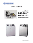
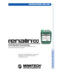
CER-1 & CER-2 Installation & Testing Instructions i Read all installation instructions completely before installing this device. 1 INTRODUCTION 2 CUSTOMER REQUIREMENTS 3 SET UP OF REPROCESSOR This document details the installation procedure for the CER-1 OPTIMA and CER-2 OPTIMA model automated endoscope reprocessors. Refer to the SITE REQUIREMENTS document (p/n 50097-820) and verify using the check list, that all site preparations are complete prior to installing the reprocessor. For installation of the Water Filtration System, refer to the CER OPTIMA WATER FILTRATION SYSTEM INSTALLATION INSTRUCTIONS (p/n 50097-822), which is supplied with the filtration system. All documents referenced in these instructions are also available at www.medivators.com. The customer is responsible for providing and installing the water supply and drain, including all necessary plumbing needs, and installation of the water filtration system. The customer is responsible for having all plumbing and drains installed and ready before the reprocessor installation. The customer is also responsible for ensuring and providing adequate electrical and ventilation. READ ALL INSTRUCTIONS COMPLETELY BEFORE STARTING INSTALLATION 1. If installing an Active Vapor Management System (AVMS) in conjunction with the reprocessor, please refer to the AVMS instructions for assembly and installation information. 2. Open the box containing the CER OPTIMA reprocessor. Place the reprocessor on either a MEDIVATORSdesigned cart or a counter top (having holes for hoses pre-drilled). 3. Open the CER OPTIMA reprocessor lid and remove all bagged items from the basin. 4. Once the unit is set into its final location, place a bubble level on the side edges of the CER OPTIMA reprocessor basin. Level the unit using the four (4) adjustable feet on the bottom of the reprocessor. Refer to Figures A and B. To adjust the level of the reprocessor, rotate the foot clockwise to raise or counterclockwise to lower the corner. Refer to Figure C. The level should be moved to the front, sides and back basin edges and the feet adjusted until the level shows all four sides are in proper level. Proper system leveling will ensure the liquid level is even when the CER OPTIMA reprocessor basin is filled and prevent the unwanted loss of disinfectant down the basin overflow opening on the back left hand corner of the basin. 1 Figure A Figure B Figure C 2 4 WATER SUPPLY 1. Attach one end of the stainless steel hose to the blue water connection labeled “Water Inlet” located on the back of the reprocessor. 2. Attach the other end of the stainless steel hose to the output T fitting of the water filter housing. 3. The water pressure must be between 40PSI (2.75 BAR) and 60 PSI (4.15 BAR) for proper operation. If the incoming water pressure is outside of this range, consult a qualified plumber to obtain the optimal pressure. Water Inlet Connection Figure 1: CER OPTIMA® Reprocessor Back Panel Attach one end of the stainless steel hose here Water outlet to CER OPTIMA reprocessor Incoming water connection Figure 2: Water Filter System 3 5 DRAIN Attach the flexible drain hose to the back of the reprocessor to the port labeled DRAIN. Use a hose clamp to secure the hose to the drain. Note: The drain hose must not loop up higher than the drain connection. Confirm there are no loops in the drain hose, and that it has a constant slope to the facility drain. The drain hose requires an air gap at the point it enters the facility drain. Note: Never use a dishwasher attachment to the sink drain, refer to Figure 3. Figure 3: Drain configuration 4 Drain requirements: 1. The facility drain must be at least 12 inches (30 cm) below the drain fitting on the reprocessor. 2. The drain must be capable of handling a discharge rate of 5 gallons (19L) per minute. 3. Eliminate all loops in the drain hose to allow proper fluid draining, refer to figure 4. 4. An open drain provides the best drain air gap and flow conditions. 5. Never use a “dishwasher” type drain attachment connected to the trap of a sink. This will result in poor machine draining and potential system alarms conditions. Incomplete draining could also result in dilution of the disinfectant chemistry or inadequate endoscope rinsing, refer to figure 3. Figure 4: 5 6 ELECTRICAL 1. Electrical Cord: For all CER OPTIMA® reprocessor models, plug the hospital-grade electrical cord FIRMLY into the power entry module located on the right side of the reprocessor (see Figure 5). Plug the other end into a power outlet having a Ground Fault Interrupter (GFI), or Residual Current Device (RCD). Power cord in power entry module Figure 5: CER OPTIMA Power Entry 6 NOTE: For maximum safety, MEDIVATORS recommends the CER OPTIMA system only be used when connected to an electrical outlet containing a Ground Fault Interrupter (GFI), or Residual Current Device (RCD). NOTE: MEDIVATORS recommends surge protectors be used for protection against electrical power spikes and surges. Consult local electrical codes to ensure proper compliance. 7 DRAIN SCREEN Make sure that the drain screen is in place (Remove the tape used for shipping). Drain screen Figure 6: CER OPTIMA® Reprocessor Basin 8 HLD RESERVOIR (High-level Disinfectant Reservoir) The reservoir can be installed: 1. Under a counter 2. In the bottom of the cart CAUTION: Do not place the disinfectant reservoir on the same level as the CER OPTIMA reprocessor. The top of the disinfectant reservoir must be lower than the bottom of the CER OPTIMA reprocessor. NOTE: It is imperative the elbow connector must be connected to the back of the reprocessor and not the reservoir. Failure to do so will prevent disinfectant from being drawn up into the reprocessor. 7 Typical placement of a reservoir in the CER OPTIMA® cart with water filters Figure 7: CER OPTIMA Cart with Reservoir and Filtration System 3. Connect the disinfectant reservoir tubing having the right-angled connector and the contained disinfectant filter, to the connection point labeled "Chemical Inlet" located on the reprocessor's back panel. Connect the other end having the straight connector to any one of the mating disinfectant reservoir connectors. The order does not matter in how the hoses are connected. 4. Connect the disinfectant reservoir tubing having the right-angled connector and no disinfectant filter, to the connection point labeled "Chemical Return" located on the reprocessor's back panel. Connect the other end having the straight connector to any one of the mating disinfectant reservoir connectors. 5. Using the supplied plug, block off the unused connection point located on the disinfectant reservoir. 9 AIR FILTER The CER OPTIMA reprocessor utilizes a 0.2 micron air filter to block any air-borne bacteria from entering the endoscope during the air purge step of the reprocessing cycle. The filter can be mounted in two different configurations. 1. The air filter is attached directly to the “AIR FILTER” connection located on the back of the reprocessor. See Figure 8. 2. The air filter connection tubing is attached to the “AIR FILTER” connection located on the back of the machine, and then the air filter is connected to the end of the tubing. This allows the air filter to be positioned to a more user-accessible position for access and replacement. See Figure 9. 3. 8 The air filters "white" connection will attach to the "white" mating connector of the machine or the air filter connections tubing. The air filters "blue" connection is then open to air (nothing is connected to it). Air filter attached directly to machine Figure 8: Air Filter Direct Connection Barcode scanner connection Air filter hose; filter attached at other end (not in photo) Figure 9: Air Filter Tubing Connection 10 BAR CODE READER The CER OPTIMA® reprocessor is equipped with a barcode reader used for scanning and recording specific information including; Endoscope ID, Operator ID, Patient ID, and Physician ID. The barcode reader is positioned in a holder which is mounted on the right side of the reprocessor. 1. Using a Phillips screw driver, attach the mounting bracket using the two mounting screws. See Figure 10. 2. Plug the barcode reader’s electrical connector into the port labeled BARCODE located on the back panel of the CER OPTIMA unit. See Figure 9. 9 Barcode scanner mounting position Figure 10: CER OPTIMA® Barcode Reader 11 FILLING THE HIGH-LEVEL DISINFECTANT (HLD) RESERVOIR Refer to the CER OPTIMA User Manual (p/n 50097-776) for instructions on filling the disinfectant reservoir. 1. For the CER-1 OPTIMA model, add four gallons of HLD. 2. For the CER-2 OPTIMA model, add five gallons of HLD 3. Verify the HLD is filled up to or slightly above the correct disinfectant reservoir level mark, for the specific CER OPTIMA model in use. 12 RESERVOIR ELECTRICAL (If using heated HLD) 1. Connect the electrical cord FIRMLY into the power entry module located on the front of the reservoir. Plug the other end into a wall outlet. 2. Turn the reservoir power switch to ON. The switch is located on the front of the heated reservoir. 3. Set the reservoir temperature display to the appropriate temperature for the HLD in use. Please note the temperature indicated on the display is the set temperature; verify the actual reservoir temperature by checking the dial thermometer located on the top of the reservoir. 4. The red light on the reservoir controller will illuminate when the reservoir is heating. Verify the reservoir is filled to the proper volume level based on the CER OPTIMA model in use. 5. Depending on the amount of fluid and the required temperature of HLD, the reservoir may take up to two hours to reach operating temperature. 10 NOTE: For maximum safety, MEDIVATORS recommends the CER OPTIMA system only be used when connected to an electrical outlet containing a Ground Fault Interrupter (GFI), or Residual Current Device (RCD). NOTE: MEDIVATORS recommends surge protectors be used for protection against electrical power spikes and surges. Consult local electrical codes to ensure proper compliance. 13 ALCOHOL The CER OPTIMA® unit has a compartment that houses the alcohol bottle, which is located on the front left-hand side of the CER OPTIMA unit and is labeled “ALCOHOL”. To open the alcohol compartment, press in on the small door indentation and then release; the door will now pop open slightly. Open the door fully to reveal alcohol bottle. The alcohol bottle should be checked daily as part of the Quality Assurance Test, and refilled or replaced if low. The alcohol compartment is designed to allow the use of round or oblong sized 500ml volume alcohol bottles. Only use 70% Ethyl Alcohol or Isopropyl Alcohol for end-of-cycle endoscope drying. See Figure 11. Figure 11: CER OPTIMA Alcohol Compartment 14 PRINTER Open the printer door and insert a new roll of thermal printer paper. The paper must be placed into the printer compartment so that the leading edge comes off the top of the roll. Pull a short length of paper from the roll and then gently close the printer door. Refer to Figure 12. Additional paper can be ordered using part number 45040061, which is a package of five rolls. Printer: Lift cover to insert paper Figure 12: CER OPTIMA Printer 11 15 TESTING THE REPROCESSOR Use this procedure for initially testing the CER OPTIMA® system, immediately after installation setup. Refer to the CER OPTIMA user manual for detailed instructions on operating the CER unit, and to perform an endoscope reprocessing cycle. 16 POWER 17 SETTING DATE AND TIME Press the power switch located on the right side of the CER OPTIMA reprocessor to ON. The CER unit will now power up. The lights on the FULL, HLD/RINSE and MANUAL buttons must be OFF. Press ↓ until the following is displayed: SET DATE 01/01/12 Press → to change the date Once the proper date is selected, press ↓ SET MONTH MONTH =01 Press → to change the month. Once the proper month is selected, press ↓ SET DAY Day =01 Press → to change the day. Once the proper day is selected, press ↓ SET YEAR Year =2012 Press → to change the year. Once the proper year is selected, press ↓ SET TIME 15:54 Press → to change the time. Once the proper time is selected, press ↓ SET HOUR Hour = 15 Press → to change the hour. Once the proper hour is selected, press ↓ SET MINUTES MINUTES= 54 Press → to change the minutes. Once the proper minutes is selected, press ↓ press ↓ until you exit the menu options 12 18 SETTING AC LINE FREQUENCY The CER OPTIMA® AC Line frequency must be set to the frequency of the country. If not set correctly, the cycle time information displayed will be inaccurate. Place the CER OPTIMA unit into an idle state, deselect/shut off the AUTOMATIC FULL and HLD/RINSE touch pads, and also the four MANUAL touch pads, so their respective green lights are OFF. 1. Press ↓ until SERVICE MENU is displayed 2. Press → to toggle between 50 and 60 Hz. When the appropriate AC Line Frequency is displayed, press ENTER. 3. Press the ↓ until back to the main menu. 19 SETTING THE DISINFECTANT TYPE The CER OPTIMA reprocessor has preset programming based on the type of disinfectant used. Disinfectant options Confirm the CER OPTIMA reprocessor is configured to run aldehyde-based HLD only: configure the unit if necessary. Selecting the correct HLD type will set the pre-programmed contact time, use temperature and required rinse cycles. Set the HLD reservoir temperature a minimum of two degrees higher than the minimum required use temperature for the selected HLD. NORTH AMERICAN MINIMUM AND MAXIMUM ALARM PARAMETERS DISINFECTANT TYPE Minimum Temp alarm HLD Contact Time Number of Rinses Maximum Temp alarm RAPICIDE® Disinfectant 35°C 5 min 2 40° RAP OPA28H 25°C 5 min 2 40° RAP OPA28U 20°C 10 min 2 40° OPA 20°C 12 min 3 40° GLUT 20°C 20 Min 2 40° GLUT 25°C 20 Min 2 40° GLUT 20°C 45 min 2 40° INTERNATIONAL MINIMUM AND MAXIMUM ALARM PARAMETERS DISINFECTANT TYPE RAP OPA INT Minimum Temp alarm HLD Contact Time Number of Rinses Maximum Temp alarm 20°C 5 min 2 40° 13 To Change the Disinfectant Type: 1. Place the CER OPTIMA® reprocessor into an idle state, deselect/shut off the AUTOMATIC FULL and HLD/ RINSE touch pads, and also the four MANUAL touch pads, so their respective green lights are OFF. 2. Press the ↓ arrow until SERVICE MENU is displayed. 3. To access the SERVICE MENU, press and hold the → arrow and then press the ↓ arrow. 4. The current programmed disinfectant type will now appear on the screen. NOTE: From the factory default is for RAPICIDE® Disinfectant For North America: Proceed to line 5. For International: Press the ↓ arrow key one time and INT’L DISINFECTANT should be displayed. Press the → arrow until the desired disinfectant type is displayed. Proceed to step 6. 5. Press the → arrow until the desired disinfectant type is displayed. 6. Press ENTER to select the disinfectant: the CER OPTIMA reprocessosr is now programmed to this disinfectant. 20 WATER 1. Connect the water supply hose to the input of the water filtration system. Refer to Figure 2. 2. Slowly open the water supply valve to the water filtration system. 3. Check for leaks on the water filtration unit and all the hose connections to the CER OPTIMA reprocessor. No water should be entering the unit at this point. If so, then turn the power OFF and contact Medivators Technical Support. 21 DRAIN 22 INSTALLATIONS OF DRAIN SCREEN AND DRAIN COVER Verify the CER OPTIMA drain hose is attached to the facility drain. Periodically check during the CER test cycle for leaks in the drain line system. 1. Install the drain screen into the drain, see Figure 13. This screen must be cleaned daily. Refer to the operations manual for details. 2. Place the drain cover over the drain screen. This cover prevents the endoscope from blocking the drain. See Figure 14. 14 Figure 13 Figure 14 23 QUALITY ASSURANCE TEST 24 OPERATION NOTE: The CER OPTIMA reprocessor configured disinfectant type will display on the CER screen during the Automatic reprocessing cycle. 25 FINAL TEST Refer to the CER OPTIMA® User Manual (p/n 50097-776) for instructions on performing the Daily Quality Assurance Test (QA Test). Run and successfully complete the QA test. Refer to the CER OPTIMA User Manual (p/n 50097-776) for instructions on proper use and operation of the CER OPTIMA automated endoscope reprocessor. Upon successful completion of the Quality Assurance Test, perform an Automatic HLD/Rinse cycle. 1. Select the AUTOMATIC HLD/RINSE cycle. 2. Press START to begin the cycle. 3. While the system is filling with water, observe the dynamic pressure readings on the three pressure gauges located on the water filtration system. The pressure on the incoming pressure gauge #1 should read between 40PSI (2.75BAR) and 60PSI (4.15BAR). Gauges #2 and #3 should be within 5PSI (0.35BAR) of the incoming water pressure gauge # 1. If the incoming water pressure is not within the 40-60PSI (2.75-4.15BAR) range, the reprocessor may experience an alarm condition and/or premature component failure due to low incoming water flow. Refer to a qualified plumber to correct the incoming water pressure to meet the specifications of the machine. See Figure 15. 15 Gauge #3 Gauge #2 Gauge #1 Water output to the reprocessor Water input Figure 15: Water Filtration System Gauges 4. When the CER OPTIMA® basin is almost full, observe the overflow drain located on the top left portion of the basin. No fluid should go down the overflow drain at this point of the cycle. If it does, the CER OPTIMA unit may not be level. Re-adjust the legs of CER OPTIMA unit until the water level is even around the top of the basin. If fluid level indicates the reprocessor is not level, refer back to section 3 to correct the machine level. See Figure 15. 16 Overflow drain. In normal operations, no fluid should go down this drain Figure 16: CER OPTIMA® Reprocessor Overflow Drain 5. If the AUTOMATIC HLD/RINSE cycle completes without errors or leaks, then run two additional error-free reprocessing cycles. Once all test cycles are completed, perform the waterline disinfection step, as outlined in the CER OPTIMA USERS MANUAL. 6. Once all of the above steps are completed, the CER OPTIMA system is ready to be placed into service. MEDIVATORS®, RAPICIDE® and CER OPTIMA® are registered trademarks of Medivators Inc. Medivators Website “Resource Center” Go to: www.medivators.com, Select “Resource Center” and “User Library” for detailed user guides and hookup information, report forms and logs, and product bulletins MEDIVATORS Customer and Technical Support Toll Free: Phone: 1-800-444-4729 · FAX: 1-866-553-9444 17 Manufactured in the USA by: Medivators Inc. 14605 28th Avenue North Minneapolis, MN 55447 USA Toll Free: +1.800.444.4729 Medivators BV Sourethweg 11 6422PC Heerlen The Netherlands Tel: +31.45.5.471.471 www.medivators.com © 2015 Medivators Inc. All rights reserved. 50097-821/E 18 Cantel Medical Asia/Pacific Pte. Ltd. 1A International Business Park #05-01 Singapore 609933 Tel: +65.6227.9698 Medivators Inc. Beijing Representative Office Room 1801, Floor 18th, Tower A, Beijing Marriott Hotel, Office Building No. 7, Jianguomen South Avenue, Dongcheng District, Beijing 100005 China Tel: +86 10 65204039