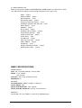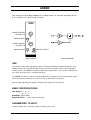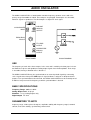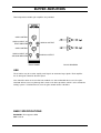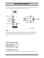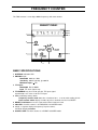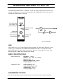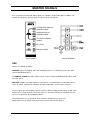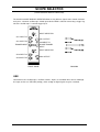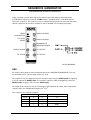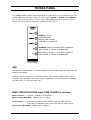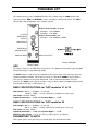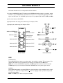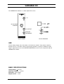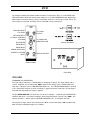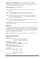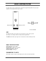
1
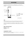
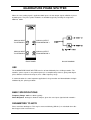
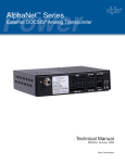
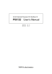
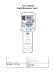
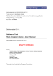
TIMS-301 USER MANUAL
Telecommunications Instructional Modelling System
TIMS-301 USER MANUAL
Author: Alfred Breznik and Carlo Manfredini
Issue Number 1.6 October 2004
All specifications are subject to change without notice.
Published by:
EMONA INSTRUMENTS PTY LTD
a.c.n. 001 728 276
86 Parramatta Road
Camperdown NSW 2050
Sydney AUSTRALIA
web: www.tims.com.au
telephone: + 61-2-9519-3933
fax:+ 61-2-9550-1378
Copyright (C) 1988 - 2004 Emona Instruments Pty Ltd and its related entities. All rights reserved.
No part of this publication may be reproduced, distributed or translated in any form or by any
means, including any network or Web distribution or broadcast for distance learning, or stored
in any database or in any network retrieval system, without the prior written constent of Emona
Instruments Pty Ltd.
For licensing information, please contact Emona Instruments Pty Ltd.
The TIMS logo
Printed in Australia
is a registered trademark of Emona TIMS Pty Ltd.
CONTENTS
Part I
TIMS INTRODUCTION
TIMS OVERVIEW
SYSTEM CONVENTIONS
Front Panel Sockets
Plug-in Modules
Labelling
Basic Modules List
Basic Specifications
Part II BASIC MODULES USER INSTRUCTIONS
Adder
Audio Oscillator
Buffer Amplifiers
Dual Analog Switch
Frequency and Event Counter
Headphone Amplifier and 3kHz LPF
Master Signals
Multiplier
Phase Shifter
Quadrature Phase Splitter
Scope Selector
Sequence Generator
Trunks Panel
Tuneable LPF
Twin Pulse Generator
Utilities Module
Variable DC
Voltage Controlled Oscillator
60kHz Lowpass Filter
1
2
3
4
5
6
7
8
9
10
12
13
15
16
17
19
20
21
23
25
26
28
TIMS INTRODUCTION
TIMS OVERVIEW
TIMS is a telecommunications modelling system. It models mathematical equations representing
electrical signals, or block diagrams representing telecommunications systems.
TIMS is primarily a hands-on rather than demonstration style teaching system, which combines
both the theoretical and practical aspects of implementing systems. We are confident that TIMS
will provide the student with a clearer understanding of the concepts behind telecommunications
theory.
Physically, TIMS is a dual rack system. The top rack accepts up to 12 Eurocard sized, compatible "black boxes", or modules. The lower rack houses a number of fixed modules, as well as the
system power supply.
The modules are very simple electronic circuits, which function as basic communications building blocks. Each module, fixed or plug-in, has a specific function; functions fall into four general
categories:
Signal Generation - oscillators, etc
Signal Processing - multipliers, filters, etc
Signal Measurement - frequency counter
Digital Signal Processing - TMS320C50 based
(DSP & Advanced Modules are not included in the BASIC TIMS-301 SYSTEM)
Modules are patched together via the front panel sockets using interconnecting leads, to model
the system under investigation.
TIMS-301 User Manual 1
SYSTEM CONVENTIONS
All TIMS modules conform to the following mechanical and electrical conventions.
A - FRONT PANEL SOCKETS
Signal interconnections are made via front panel, 4mm sockets
Sockets on the LEFT HAND SIDE are for signal INPUTS.
All inputs are high impedance, typically 56k ohms.
Sockets on the RIGHT HAND SIDE are for signal OUTPUTS.
All outputs are low impedance, typically 330 ohms.
YELLOW sockets are only for ANALOG signals.
ANALOG signals are held near the TIMS standard reference level of 4V pk-pk.
RED sockets are only for DIGITAL signals.
DIGITAL signals are TTL level, 0 to 5 V.
GREEN sockets are all common, or system GROUND.
Note that input and output impedances are intentionally mismatched, so that signal connections
may be made or broken without changing signal amplitudes at module outputs.
B - PLUG-IN MODULES
Any plug-in module may be placed in any of the 12 positions of the upper rack. All modules use
the back plane bus to obtain power supply : only the DSP modules (not part of the BASIC SYSTEM) use the bus to transfer signals. The modules are designed so that they may be plugged-in
or removed at any time, without turning off the system power. The modules are not locked
into position and may need to be held while interconnecting leads are removed.
C - LABELLING
All modules are identified as to the function they perform.
Inputs, outputs, controls and switches are labelled so that a student who has had only a brief introduction to TIMS can use the modules without needlessly referring back to this USER
MANUAL.
It should be noted that no variable controls have calibration marks. This is intentional, as the philosophy behind TIMS is that students setup and adjust systems by observing and measuring signals. This assists the student in gaining a much greater understanding, feel and insight into the
operation of a communications implementation.
TIMS-301 User Manual 2
D - BASIC MODULE LIST
Below are listed all the BASIC SYSTEM MODULES. FIXED modules are located in the lower
rack, while PLUG-IN modules can be positioned anywhere in the upper rack.
Adder - plug-in
Audio Oscillator - plug-in
Buffer Amplifiers - fixed
Dual Analog Switch - plug-in
Frequency and Event Counter - fixed
Headphone Amplifier and 3kHz LPF - fixed
Master Signals - fixed
Multiplier - plug-in
Phase Shifter - plug-in
Quadrature Phase Splitter - plug-in
Scope Display Selector - fixed
Sequence Generator - plug-in
Trunks Panel - fixed
Tuneable LPF - plug-in
Twin Pulse Generator - plug-in
Utilities Module - plug-in
Variable DC - fixed
Voltage Controlled Oscillator - plug-in
60kHz Lowpass Filter - plug-in
BASIC SPECIFICATIONS
POWER SUPPLY
Input 120, 127, 220 or 240V AC, 47Hz to 63Hz
Output + 15V, 2.2A DC
-15V, 2.2A DC
Protection short circuit, overload, thermal
Regulation 0.2%
PHYSICAL
Case Dimensions 490(W) x 330(D) x 310(H) mm
System Weight 10kg
Plug-in Card Dimensions 160 x 100 mm
Plug-in Card Bus Connectors 64 way, 2 row, Eurocard
MODULES
Specifications for each module are listed in the following pages.
TIMS-301 User Manual 3
ADDER
Two analog input signals A(t) and B(t) may be added together, in adjustable proportions G and
g. The resulting sum is presented at the output.
G:GAIN CONTROL
FOR INPUT A
ANALOG INPUT
g:GAIN CONTROL
FOR INPUT B
ANALOG OUTPUT
ANALOG INPUT
FRONT PANEL
BLOCK DIAGRAM
USE
Care must be taken when adjusting the gains to avoid overloading the following modules. Overloading will not cause any damage but it means non-linear operation, which is to be avoided in
analog systems. The ADDER is capable of delivering a signal well in excess of the standard reference level, 4V pk-pk, given a standard level input.
The ADDER can also be used as a normal amplifier by using only one input and turning the gain
of the other input to minimum. It is not necessary to ground the unused input.
Note that gains G and g are negative. All inputs and outputs are DC coupled.
BASIC SPECIFICATIONS
Gain Range 0 < G < 2;
0 < g < 2;
Bandwidth approx 1MHz
Output DC Offset < 10mV, open circuit inputs
PARAMETERS TO NOTE
maximum output level; linearity; polarity inverting; phase shift
TIMS-301 User Manual 4
AUDIO OSCILLATOR
The AUDIO OSCILLATOR is a low distortion tuneable frequency sinewave source with a frequency range from 500Hz to 10kHz. Three outputs are provided. Two outputs are sinusoidal,
with their signals in quadrature. The third output is a digital TTL level signal.
INPHASE
ANALOG
OUTPUT
SYNCHRONIZE
INPUT
FREQUENCY
ADJUST
TTL LEVEL
OUTPUT
QUADRATURE
ANALOG
OUTPUT
FRONT PANEL
BLOCK DIAGRAM
USE
The frequency of each of the three outputs is the same and is varied by the front panel ∆ f control. Both the in-phase and quadrature analog output signals have fixed amplitude. Their shape
is sinusoidal, having a distortion of less than 0.1%.
The AUDIO OSCILLATOR may be synchronized to an external periodic signal by connecting
such a signal to the front panel SYNC input. A signal of about 1 volt peak is adequate for this
purpose. For synchronization to be achieved, the AUDIO OSCILLATOR must be manually tuned
to within a few percent of the frequency to which synchronization is desired.
BASIC SPECIFICATIONS
Frequency Range 300Hz to 10kHz
Analog Output Level 4V pk-pk
Distortion < 0.1% analog outputs only
Digital Output TTL level
PARAMETERS TO NOTE
frequency range; relative phase of outputs; amplitude stability with frequency range; harmonic
content; short term stability; synchronizing characteristic.
TIMS-301 User Manual 5
BUFFER AMPLIFIERS
Two independent variable gain amplifiers are provided.
GAIN CONTROL
ANALOG INPUT OF
FIRST AMPLIFIER
ANALOG OUTPUT
GAIN CONTROL
ANALOG INPUT OF
SECOND AMPLIFIER
ANALOG OUTPUT
FRONT PANEL
BLOCK DIAGRAM
USE
These buffers may be used to amplify small signals or attenuate large signals. Each amplifier
has its own gain control on the front panel.
Care should be taken to ensure that later modules are not overloaded due to excessive gain.
Overload will not cause any damage but it means non-linear operation, which is to be avoided in
analog systems. If overload occurs, turn the gain control counter clockwise.
BASIC SPECIFICATIONS
Bandwidth DC to approx 1MHz
Gain 0 to 10
TIMS-301 User Manual 6
DUAL ANALOG SWITCH
Two identical analog switches are controlled by digital, TTL level signals. The outputs of the two
switches are added internally and presented at the output of the module.
ANALOG INPUT 1
TTL CONTROL
FOR INPUT 1
TTL CONTROL
FOR INPUT 2
ANALOG INPUT 2
OUTPUT
FRONT PANEL
BLOCK DIAGRAM
USE
Each switch may be closed independently by a TTL HIGH at the respective control input. The
switch outputs are combined internally and are presented at the common output socket. Open
circuit voltage gain between each input and the module output is unity when the switch is
closed.
BASIC SPECIFICATIONS
Analog Input Bandwidth > 300kHz
Maximum CONTROL clock > 100kHz
CONTROL Input Levels TTL only
Maximum Analog Input Level + 8V
PARAMETERS TO NOTE
switch On/Off ratio; linearity; switching speed; analog bandwidth; channel cross talk; DC off-set
TIMS-301 User Manual 7
FREQUENCY COUNTER
The TIMS counter is an 8 digit, 10MHz frequency and event counter.
9
8
7
1
2
6
3
4
5
BASIC SPECIFICATIONS
1 OVERflow indication LED
2 ANALOG input:
Bandwidth 40Hz to 1 MHz
Sensitivity 250mV typically, @ 100kHz
Maximum input + 12V
3 TTL Input:
Bandwidth DC to 10MHz
Input TTL level signals only
4 TTL ENABLE may be used to gate the TTL input signal.
Specifications are same as for the TTL input.
5 Mode and Range rotary switch
Frequency counter mode Gate time selection of 0.1s, 1s or 10s with reading in kHz
Event counter mode displays number of pulses counted since the last RESET
6 RESET Push Button resets the count of the Event Counter to zero
7 kHz LED is lit when counter is in FREQUENCY COUNTER mode
8 8 digit, 7 segment display of frequency or pulse counts;
maximum display 99999999
9 COUNTS LED is lit when counter is in EVENT COUNTER mode
TIMS-301 User Manual 8
HEADPHONE AMPLIFIER and 3kHz LPF
The HEADPHONE AMPLIFIER is a wideband, variable gain audio amplifier which will drive standard 8ohm headphones or a speaker. An independent 3kHz LOWPASS FILTER may be switched
in before the audio amplifier, if required.
FOR SWITCHING
LPF OUTPUT TO
AMPLIFIER INPUT
LOWPASS FILTER
OUTPUT
AMPLIFIER
GAIN ADJUST
AMPLIFIER AND
FILTER INPUT
HEADPHONE
OUTPUT
FRONT PANEL
BLOCK DIAGRAM
USE
This module serves as an electro-acoustic interface between the audio signals within the system
and the user. Included within the HEADPHONE AMPLIFIER module is an independent LOWPASS FILTER with a 5th order elliptic characteristic. The filter’s cutoff frequency is 3kHz, stopband attenuation is 50dB and passband ripple is 0.2dB.
BASIC SPECIFICATIONS
AUDIO AMPLIFIER
Bandwidth < 100kHz
THD 0.2% (RL= 8ohms, P= 125mW)
Maximum Gain 20
Maximum Output Power 500mW
Output Impedance 8 ohms
LOWPASS FILTER
Cutoff Frequency 3kHz
Stopband Attenuation 50dB
Passband Gain approx 1
Passband Ripple 0.2dB
PARAMETERS TO NOTE
filter corner point; filter shape; passband ripple; out-of- band attenuation; amplifier distortion
TIMS-301 User Manual 9
MASTER SIGNALS
Five synchronized analog and digital signals are available, ranging from 2kHz to 100kHz. The
function and frequency of each signal is indicated on the front panel.
QUADRATURE ANALOG
CARRIER SIGNAL
INPHASE ANALOG
CARRIER SIGNAL
TTL LEVEL CARRIER
SIGNAL
TTL LEVEL
ANALOG SIGNAL
FRONT PANEL
BLOCK DIAGRAM
USE
Signals are labelled as follows:
CARRIER signals are 100kHz, which for modelling purposes is sufficiently far from the audio
channel bandwidth of 3kHz.
The SAMPLE CLOCK of 8.3kHz, which may be used to sample bandwidth-limited (3kHz) audio
message signals.
MESSAGE provides an audio frequency signal which is synchronized to a sub-multiple of the
carrier to enable ’text-book’ like displays of simple modulation schemes to be achieved.
The five signals are derived from a master crystal oscillator resulting in low frequency drift. Their
frequencies are fixed internally. The output levels are also fixed. To vary the amplitude, the signals may be applied to the neighboring buffers.
The analog signals are sinusoidal in shape, having a distortion of less than 0.1%.
Digital signals are all standard TTL level, with rise times of better than 80nsec.
TIMS-301 User Manual 10
BASIC SPECIFICATIONS
Output Frequencies 100kHz, carrier
8.333kHz, sample clock
2.083kHz, audio (carrier sub-multiple)
Output Levels 4V pk-pk, analog
TTL level, digital
Distortion < 0.1%, analog outputs only
PARAMETERS TO NOTE
short term frequency stability; relative phase of quadrature outputs; harmonic content.
TIMS-301 User Manual 11
MULTIPLIER
Two analog input signals X(t) and Y(t) may be multiplied together. The resulting product is
scaled by a factor of approximately 1/2 so that, with standard level inputs, later stages are not
overloaded.
INPUT COUPLING
SWITCH
ANALOG INPUT
ANALOG OUTPUT
ANALOG INPUT
FRONT PANEL
BLOCK DIAGRAM
USE
The input coupling switch may be used to remove input DC components by switching to AC
coupling. It should be noted that any DC component in the output will not be removed.
The "k" factor (a scaling parameter associated with "four quadrant" multipliers) is approximately
one half. It is defined with respect to the OUTPUT from the module and may be measured experimentally.
BASIC SPECIFICATIONS
Bandwidth approx 1MHz
Characteristic k.X(t).Y(t)
k approx 1/2
PARAMETERS TO NOTE
linearity; k factor; carrier leak; phase response; DC off-set; performance as a squarer; frequency
response; "conversion gain" as a (de)modulator.
TIMS-301 User Manual 12
PHASE SHIFTER
The PHASE SHIFTER introduces a phase shift between its input and output. This phase shift is
adjustable by the user. The frequency range of operation can be selected by PCB mounted
switch.
BLOCK DIAGRAM
COARSE PHASE
ADJUST
FINE PHASE
ADJUST
180O PHASE
CHANGE
ANALOG OUTPUT
ANALOG INPUT
FRONT PANEL
PCB VIEW
USE
This variable PHASE SHIFTER is capable of varying the magnitude of the phase shift through
360 degrees in two steps. The 180 degree switch selects the step or region of interest; the
COARSE and FINE controls are used to then obtain the required phase shift, Φ.
If the input is COS(µt), then the output is COS(µt- Φ), where Φ lies between 0 and 180 degrees.
Although the PHASE SHIFTER will operate from a few hertz up to 1MHz it has been optimized
to operate in the neighborhood of two frequencies: around 100kHz in the HI range and around
2kHz in the LO range. A PCB mounted switch is used to select the frequency range.
The open circuit gain through the PHASE SHIFTER is essentially unity for all phases, but note
that the amount of phase shift, Φ, is a function of frequency. This is NOT a wideband phase
changer: thus all the frequency components of a complex signal’s spectra are not shifted by the
same phase.
TIMS-301 User Manual 13
BASIC SPECIFICATIONS
Bandwidth < 1MHz
Frequency Range HI approx 100kHz *
LO approx 2kHz *
* For 0 to 360 degree range of phase shift. The phase shift range increases (i.e. resolution
decreases) as the input frequency increases.
Coarse approx 180 degrees shift
Fine approx 20 degrees shift
PARAMETERS TO NOTE
Variation of phase change with frequency change.
TIMS-301 User Manual 14
QUADRATURE PHASE SPLITTER
When the same analog signal is applied to both inputs, the two output signals will differ in phase
by 90 degrees. The phase splitter networks are wideband, typically covering the range from
200Hz to 10kHz.
ANALOG INPUT
TO NETWORK 1
ANALOG OUTPUT
FROM NETWORK 1
ANALOG INPUT
TO NETWORK 2
ANALOG OUTPUT
FROM NETWORK 2
FRONT PANEL
BLOCK DIAGRAM
USE
The QUADRATURE PHASE SPLITTER consists of two wideband phase shifting networks. The
networks’ phase responses vary with frequency in a complimentary manner, giving a 90 degree
phase difference between the outputs, over a wide frequency range.
In communications the most important application is the generation and demodulation of Single
Sideband by the "phasing method".
BASIC SPECIFICATIONS
Frequency Range 200Hz to 10kHz typically
Phase Response 90 degrees between outputs, given the same input signal to both networks.
PARAMETERS TO NOTE
Phase error from 90 degrees. This may be measured directly (difficult !) or calculated from sideband suppression measurements.
TIMS-301 User Manual 15
SCOPE SELECTOR
(OSCILLOSCOPE DISPLAY SELECTOR)
The OSCILLOSCOPE DISPLAY SELECTOR allows 2 of 4 different signals to be viewed simultaneously on a 2 channel oscilloscope. A third input labeled TRIG is ideal for connecting a trigger signal to the oscilloscope’s external trigger input.
INPUT SELECTOR
CH1 INPUT "A"
CH1 OUTPUT
CH1 INPUT "B"
CONNECT TO
SCOPE TRIGGER
INPUT
TRIGGER INPUT
INPUT SELECTOR
CH2 INPUT "A"
CH2 OUTPUT
CH2 INPUT "B"
FRONT PANEL
DIAGRAM
USE
Connection to the oscilloscope is via BNC sockets. Inputs are standard 4mm sockets. Although
the input sockets are YELLOW (analog), either analog or digital signals may be examined.
TIMS-301 User Manual 16
SEQUENCE GENERATOR
(PSEUDORANDOM SEQUENCE GENERATOR)
Using a common external clock signal, the sequence generator outputs two independent
pseudorandom sequences X and Y. A SYNC output is provided which is coincident with the
start of the sequences. The sequences may be stopped and restarted at any time via front panel
controls. Sequences X and Y are available as either standard TTL or analog level output.
RESET
PUSH BUTTON
ANALOG OUTPUT
TTL LEVEL
RESET
ANALOG OUTPUT
BEGINNING OF
SEQUENCE SYNCH
ANALOG CLOCK
TTL OUTPUT
TTL CLOCK
TTL OUTPUT
FRONT PANEL
BLOCK DIAGRAM
USE
An external clock signal must be provided to operate the SEQUENCE GENERATOR. This may
be sinusoidal or TTL: separate input sockets are used.
The sequences may be stopped at any time by either depressing the RESET button or applying
a TTL HI signal to the RESET input. To restart the sequences from the beginning, release the
RESET button or apply a TTL LO to the RESET input.
The length of the sequences may be selected by a PCB mounted dip switch. Four independent
sequence pairs are available from lengths of 25 to 211.
The sequences are selected as follows:
DIP SWITCH CODE
n
SEQUENCE LENGTH 2n
msb 0
0
5
32
0
1
8
256
1
0
8
256
1
1
11
2048
TIMS-301 User Manual 17
BASIC SPECIFICATIONS
Input Clock Range TTL 1Hz to 1MHz
Analog < 500Hz to > 10kHz
Number of Sequences 4 pairs
Sequence Lengths 25, 28, 28, 211
Sync indicates start of sequence
PARAMETERS TO NOTE
sequence distribution; noise generation using pseudorandom sequences.
TIMS-301 User Manual 18
TRUNKS PANEL
The TRUNKS PANEL provides inputs and outputs to signals which are transmitted along the OPTIONAL TIMS BUS classroom network. The three outputs SIGNAL 1, SIGNAL 2 and SIGNAL 3
present signals from the lecturer’s master system. IN and OUT allow for signals to be respectively received from and transmitted to a neighboring TIMS system.
SIGNALS 1, 2 & 3
COME FROM THE
MASTER TIMS SYSTEM
IF TRUNKS IS CONNECTED
INCOMING SIGNAL FROM ADJACENT STUDENT’S
TIMS SYSTEM, IF TRUNKS IS CONNECTED
OUT SENDS A SIGNAL TO THE NEXT STUDENT’S
TIMS SYSTEM, IF TRUNKS IS CONNECTED
FRONT PANEL
USE
Note that the TRUNKS PANEL is a module that differs from the TIMS’ front panel color code and
alignment conventions.
Though the inputs and outputs are YELLOW (analog), either analog or digital signals may be
used. Also, the signal input, OUT, which accepts a signal that is to be transmitted to a neighboring TIMS system, is on the right hand side.
BASIC SPECIFICATIONS when TIMS-TRUNKS is installed
Master Channels 3 : SIGNAL 1, SIGNAL 2 and SIGNAL 3;
Master Channel Bandwidth 700kHz (typ), ac coupled.
Local Channels 2 : IN brings the incoming signal FROM an adjacent TIMS’ OUT port.
OUT carries the outgoing signal TO the other adjacent TIMS’ IN port.
Local Channel Bandwidth 350kHz (typ), ac coupled
TIMS-301 User Manual 19
TUNEABLE LPF
The cutoff frequency of this LOWPASS FILTER can be varied using the TUNE control. Two
frequency ranges, WIDE and NORMAL, can be selected by a front panel switch. The GAIN
control allows signal amplitudes to be varied if required.
CLK for TLPF modules V1 to V3:
CLK/880 = f-3dB; NORMAL
CLK/360 = f-3dB; WIDE
CLK for TLPF modules V4:
CLK/100 = f-3dB; NORMAL & WIDE
CUT-OFF
FREQUENCY
ADJUST
GAIN ADJUST
FREQUENCY
RANGE SELECT
ANALOG OUTPUT
ANALOG INPUT
BLOCK DIAGRAM
USE
FRONT PANEL
This lowpass filter has an elliptic filter characteristic. The stopband attenuation is typically 50dB
and passband ripple is approximately 0.5dB.
The GAIN control is used to vary the amplitude of the output signal. Care should be taken to
avoid overloading/saturation. Two frequency ranges are provided. NORMAL range provides
more precise control over the lower audio band, used for telecommunications message
channels. The WIDE range expands the filter’s range to above 10kHz. The CLK output provides
an indication of the filter’s cutoff frequency.
BASIC SPECIFICATIONS for TLPF modules V1 to V3
Filter Ranges 900 Hz < NORMAL < 5 kHz and
2.0 kHz < WIDE < 12 kHz, continuously variable over each range.
Filter Order 7th order, Elliptic
Stopband Attenuation > 50dB and Passband Ripple < 0.5dB
BASIC SPECIFICATIONS for TLPF modules V4
Filter Ranges 200 Hz < NORMAL < 5 kHz and
200 Hz < WIDE < 12 kHz, continuously variable over each range.
Filter Order 5th order, Elliptic
Stopband Attenuation > 50dB and Passband Ripple < 0.5dB
Maximum Input Voltage + 5V to -5V (TTL-level input signal is acceptable)
PARAMETERS TO NOTE
corner point; phase shift; gain range; passband ripple; out of band attenuation.
TIMS-301 User Manual 20
TWIN PULSE GENERATOR
(TWIN PULSE GENERATOR - VERSION 2.0)
A positive going edge applied at the CLOCK input causes a positive pulse to occur at the output terminals. There are two operating modes: TWIN and SINGLE. Only TWIN mode is limited to
low frequency CLOCK inputs.
In TWIN mode, Q1 outputs the leading pulse and Q2 outputs the delayed pulse. The time between pulses Q1 and Q2 can be varied, as can the pulses’ widths.
In SINGLE mode, only Q1 outputs a positive going pulse, while Q2 outputs the inverse of Q1.
The pulse width can be varied.
ERROR LED, INDICATES
IF 2tW + tD > tCLK
BLOCK DIAGRAM
PULSE WIDTH
CONTROL
DELAYED PULSE
OUTPUT:
TTL LEVEL
LEADING PULSE
OUTPUT:
AC COUPLED
DELAY TIME
CONTROL
DIGITAL CLOCK
TTL LEVEL OUT
FRONT PANEL
TIMING DIAGRAM
USE
A digital TTL level signal is applied to the CLK input. The GENERATOR then outputs one or two
pulses, depending upon the operating mode selected. Use the PCB mounted MODE switch to
select either SINGLE or TWIN operating mode.
TWIN MODE
TWIN mode is used when two sequential pulses are needed. Two equal width positive pulses occur as a result of each CLK signal positive edge. Pulse Q1 always occurs before pulse Q2. The
width of both pulses is controlled by the front panel WIDTH control. The DELAY control varies
the spacing between the two pulses. Note that TWIN mode will only accept CLOCK input signals
of up to 50kHz, depending upon front panel settings.
If WIDTH and DELAY have been incorrectly set, causing anomalous operation, the ERROR
LED will be lit. To eliminate the error reduce DELAY and then WIDTH - by turning counter clockwise.
TIMS-301 User Manual 21
SINGLE MODE
SINGLE mode is used to obtain a train of equal width pulses from any TTL level signal.
Equal width positive pulses occur at Q1 output as a result of each CLK signal positive edge. The
width of the pulses is controlled by the front panel WIDTH control. Q2 simultaneously outputs
the compliment of Q1. The DELAY control is not used in this mode.
Note that Q1 includes both a TTL level and an AC coupled output pulse.
BASIC SPECIFICATIONS
TWIN MODE
Clock Frequency Range < 50kHz
Pulse WIDTH 3µs < tw < 25µs
Pulse DELAY Q2-Q1 10µs < td < 120µs
Error Indication 2tw + td > tCLK
SINGLE MODE
Clock Frequency Range < 200kHz
Pulse WIDTH 3µs < tw < 25µs
TIMS-301 User Manual 22
UTILITIES MODULE
The Utilities Module houses 4 independent functional blocks:
(i) A signal COMPARATOR with TTL output and CLIPPER with bipolar output, for squaring analog
waveforms. The COMPARATOR’s threshold level may be set as required by applying a DC voltage to the REF input. The CLIPPER’s gain may be set by adjusting DIP switches SW1 and SW2.
(ii) Precision halfwave RECTIFIER.
(iii) Simple diode and single pole, audio range, RC Lowpass Filter.
(iv) Single pole, audio range, RC Lowpass Filter.
CLIPPER
BIPOLAR OUTPUT
ANALOG REFERENCE
INPUT
ANALOG SIGNAL
INPUT
COMPARATOR
TTL OUTPUT
ANALOG INPUT
ANALOG OUTPUT
ANALOG INPUT
ANALOG OUTPUT
ANALOG INPUT
ANALOG OUTPUT
FRONT PANEL
BLOCK DIAGRAM
USE
COMPARATOR
The COMPARATOR will square any analog signal and provide a standard TTL level output. The
switching threshold level is determined by the voltage level applied to the REF input.
NOTE: For correct COMPARATOR operation, the REF input must never be left unconnected.
The REF input may be connected to GROUND, VARIABLE DC or any other signal source.
CLIPPER
The CLIPPER will amplify any analog TIMS level signal and then clip the amplitude of the amplified signal, to a fixed level of approximately + 1.8V. The clipping action is performed by standard small signal diodes.
NOTE: The REF input is NOT used by the CLIPPER.
TIMS-301 User Manual 23
Adjusting the gain of the CLIPPER, determines whether the clipping action is "SOFT", "MEDIUM"
or "HARD". The following table, UTIL-1, relates DIP switch settings to CLIPPER gains and clipping action,
CLIPPING
GAIN
DIP SWITCH SETTINGS
ACTION
(approx)
SW1 (both a & b)
SW2 (both a & b)
SOFT
x0.8
ON - ON
OFF - OFF
MEDIUM
x8
OFF - OFF
OFF - OFF
HARD
x40
OFF - OFF
ON - ON
-
not applicable
ON - ON
ON - ON
Table UTIL-1: CLIPPER gain settings
DIP switches SW1 and SW2 will be found in the middle of the UTILITIES module’s circuit board.
NOTE: Both halves (bits) of each switch must be in the SAME position at all times.
BASIC SPECIFICATIONS
COMPARATOR
Operating Range > 500kHz
TTL Output Risetime 100nsec (typ)
CLIPPER
Operating Range > 500kHz
Output Level 1.8Vpk (typ)
Adjustable Gains 3 steps; x0.8, x8 and x40 (approx)
RECTIFIER
Bandwidth DC to 500kHz (approx)
DIODE & LPF
LPF -3dB 2.8kHz (approx)
RC LPF
LPF -3dB 2.8kHz (approx)
TIMS-301 User Manual 24
VARIABLE DC
The VARIABLE DC module is a stable, bipolar DC source.
+ 5V
DC VOLTAGE
CONTROL
DC OUTPUT
GROUND
REFERENCE
FRONT PANEL
BLOCK DIAGRAM
USE
The DC voltage output varies from about -2.5V when the control is fully counter clockwise
through zero to + 2.5V when control is turned fully clockwise. If greater resolution or wider
range is required, then one of the BUFFER AMPLIFIERS can be used in conjunction with the
VARIABLE DC module.
BASIC SPECIFICATIONS
Voltage Range + 2.5V DC
Short-term Stability < 2mV/hr
Resolution approx 20mV
Output Current < 5mA
TIMS-301 User Manual 25
VCO
The Voltage Controlled Oscillator module functions in two modes: either as a VOLTAGE CONTROLLED OSCILLATOR with analog input voltage or as an FSK GENERATOR with digital input.
Both modes have two frequency ranges of operation which are selected by a range switch. The
VCO frequency and input sensitivity can be controlled from the front panel.
FSK DATA INPUT
- TTL LEVEL
TTL LEVEL
OUTPUT
SET SENSITIVITY
OF INPUT CONTROL
VOLTAGE
Vin OVERLOAD
INDICATION LED
SET CENTER
FREQUENCY
BLOCK DIAGRAM
FREQUENCY
RANGE SELECTION
CONTROL VOLTAGE
INPUT
ANALOG OUTPUT
FRONT PANEL
PCB VIEW
VCO USE
STANDARD VCO OPERATION
The VCO output frequency is controlled by an analog input voltage. The input voltage, Vin, is
scaled - amplified - by the front panel GAIN control. A DC voltage can be added to Vin internally, thus setting the start or CENTER FREQUENCY, fo . The CENTER FREQUENCY is defined
as the VCO output frequency, when no voltage is applied to the Vin connector. The Vin input is
internally tied to ground if no signal is applied.
The Vin OVERLOAD LED is lit when the sum of these voltages - scaled Vin plus CENTER FREQUENCY DC offset - exceed the oscillator’s internal operating limits. Decrease the GAIN - turn
counter clockwise - and/or shift the CENTER FREQUENCY, fo , to extinguish the LED.
The frequency range switch selects between the HI or carrier band and the LO or audio band.
Both sinewave and digital outputs are available.
TIMS-301 User Manual 26
SPECIAL VCO OPERATION - FINE FREQUENCY CONTROL
In some applications, fine control may be required over the output frequency of the VCO. This
may be easily achieved by following these four steps:
MODULES REQUIRED: VCO and VARIABLE DC.
STEP 1 - Set the VARIABLE DC module’s output close to zero (marker knob at 12 o’clock
position).
STEP 2.1 - Turn the GAIN control of the VCO to zero, fully counter-clockwise.
STEP 2.2 - Now, turn the GAIN control up, clockwise, just a little (only a few degrees).
STEP 3 - Set the VCO module’s output frequency as close as possible to the frequency of
interest. Use the frequency adjust knob, fo. Use the FREQUENCY COUNTER to
measure the VCO’s output frequency.
STEP 4 - Finally, patch the VARIABLE DC module’s output to the VCO module’s frequency
control input, Vin, with a standard patching lead.
FINE FREQUENCY CONTROL of the VCO module is now achieved by turning the VARIABLE DC
module’s voltage control knob.
FSK USE
A PCB mounted slide switch selects between FSK and VCO modes of operation. The two output frequencies, FSK1 and FSK2 , (MARK and SPACE), are set by varying the PCB mounted, finger adjustable trimmers. As in VCO mode, the frequency range switch selects between the HI or
carrier band and the LO or audio band. The digital data input accepts only TTL level signals.
Both sinewave and digital outputs are available.
GAIN and CENTER FREQ, fo , controls and the Vin connector are not used in the FSK mode.
BASIC SPECIFICATIONS
VCO MODE
Frequency Ranges 1.5kHz < LO < 17kHz; sinewave and TTL
( < 300Hz with external input voltage, Vin )
70kHz < HI < 130kHz; sinewave and TTL
Input Voltage -3V < Vin < 3V
Overload limit indication LED Vvco > + 3V;
Vvco is the internal voltage finally applied to the VCO circuitry.
GAIN G.Vin : 1 < G < 2
Center Frequency Voltage Range - 3V < Vfc < 3V;
Vfc is a DC voltage added INTERNALLY to G.Vin
FSK MODE
Frequency Ranges 1.5kHz < FSK1, LO < 9kHz
500Hz < FSK2, LO < 4kHz
80kHz < FSK1, HI < 200kHz
20kHz < FSK2, HI < 120kHz
Data Input TTL level message
TIMS-301 User Manual 27
60kHz LOWPASS FILTER
An elliptic lowpass filter is provided with a cutoff point of approximately 60kHz. The input signal
amplitude can be adjusted with the gain control.
ANALOG OUTPUT
ANALOG INPUT
FRONT PANEL
BLOCK DIAGRAM
USE
The 60kHz LPF allows carrier signals to be removed from a given signal spectrum.
For example, as the lowpass filter for envelope detector applications.
The GAIN control allows input signals to be attenuated, to avoid overloading the filter.
BASIC SPECIFICATIONS
Cutoff Frequency approx 60kHz
Passband Gain variable, 0 to 5 (approx)
Stopband Attenuation 50dB (typ)
Passband Ripple 0.1dB (typ)
PARAMETERS TO NOTE
corner point; response shape; passband ripple; phase shift; out of band attenuation.
TIMS-301 User Manual 28
TIMS-301/C Safety Information
The Emona TIMS-301/C User Manual contains important information and warnings which have to be
followed by the user to ensure safe operation.
The TIMS-301/C System is Safety Class I laboratory equipment and is designed to meet the requirements
of EN61010-1. The Installation Category is Category II, intended for operation from a normal single phase
supply.
The TIMS-301/C System has been designed for indoor use in a Pollution Degree I environment (no
pollution, or only dry non-conductive pollution) in the temperature range of 5 degrees C to 40 degrees C,
20% to 80% RH (non-condensing). It may occasionally be subjected to temperature between +5 degrees
and -10 degrees without degradation of its safety.
WARNING! TIMS EQUIPMENT MUST BE EARTHED
Any interruption of the mains earth conductor inside or outside the equipment will make the equipment
dangerous. Intentional interruption is prohibited.
Make sure that only fuses with the required rated current and of the specified type are used for
replacement.
Use of this equipment in a manner not specified by these instructions may impair the safety protection
provided. Do not operate the equipment outside its rated supply voltages or environmental range. In
particular, excessive moisture may impair safety.
Front Panel Connections
- INPUT SOCKETS, RED
WARNING!
DO NOT APPLY EXTERNAL VOLTAGES EXCEEDING +5.5V or -0.5V
and FREQUENCIES EXCEEDING 1MHz.
- INPUT SOCKETS, YELLOW
WARNING!
DO NOT APPLY EXTERNAL VOLTAGES EXCEEDING +/-15V
and FREQUENCIES EXCEEDING 200kHz.
- OUTPUT SOCKETS, RED and YELLOW
WARNING!
DO NOT APPLY EXTERNAL VOLATGES TO ANY OUTPUT SOCKET
Safety Terms and Symbols
WARNING. Warning of potential hazard
O
I
mains supply OFF
mains supply ON
Installation
Check the operating voltage marked on the rear panel is suitable for the local supply. Should it be
necessary to change the operating voltage, please contact your supplier or Emona Instruments Pty Ltd.
FUSE
Ensure that the correct mains fuse is fitted for the set operating voltage, as follows:
for 220 or 240V operation:
for 110V or 127V operation
630mA (T) 250 V
1.2A (T) 250V
MAINS LEAD
Ensure an approved type IEC mains lead with earth connection is used.
WARNING! TIMS EQUIPMENT MUST BE EARTHED
Any interruption of the mains earth conductor inside or outside the equipment will make the equipment
dangerous. Intentional interruption is prohibited.
MOUNTING
The equipment is designed for bench use.
Sicherheitsanweisung für das System TIMS-301/C
Die Gebrauchsanweisung des Systems TIMS-301/C beinhaltet wichtige Informationen und
Sicherheitswarnungen, die vom Benutzer beachtet werden müssen.
Dieses System ist ein Laborgerät der Sicherheitsklasse 1, das der Norm EN 61010-1 und der
Kategorie 2 entspricht und für einphasigen Strom vorgesehen ist.
Es ist nur für den Betrieb in Innenräumen zulässig, in einer Umgebung des Verschmutzungsgrades 1
( keine Verschmutzung oder trockene, nichtleitende Verschmutzung ), bei Temperaturen
zwischen 5 und 40°Celsius und 20-80% relativer Luft feuchtigkeit (ohne Kondensation).
Achtung! Das TIMS System muss geerdet werden
Jedes Abtrennen der Masseleitung im Inneren oder Äußeren des Systems ist lebensgefährlich. Der
Schutzleiter darf auf keinen Fall unterbrochen werden.
Benutzen Sie ausschließlich Sicherungen, deren Nennstrom und Typ den spezifizierten Werten
entsprechen.
Jeder Gebrauch dieses Apparats unter Bedingungen, die in dieser Gebrauchsanweisung nicht
festgesetzt sind, kann die Sicherheit beeinträchtigen. Benutzen Sie den Apparat keinesfalls außerhalb
der spezifizierten Versorgungsspannung oder der beschriebenen atmosphärischen Bedingungen. Ein
Übermaß an Feuchtigkeit vermindert die Sicherheit.
Frontplattenanschlüsse
ROTE EINGÄNGE
Achtung! Keine externe Spannung > +5,5 V / < -0,5 V oder Signale
anschließen.
> 1 MHz
GELBE EINGÄNGE
Achtung! Keine externe Spannung die +/-15 V übersteigt oder Signale mit einer
Frequenz > 200 MHz anschließen
ROTE UND GELBE AUSGÄNGE
Achtung! Keine Signale an die Ausgänge anlegen
Sicherheitssymbole und Sicherheitsbegriffe
ACHTUNG. Warnung bezüglich eines Gefahrenpotentials
O
Stromversorgung ausgeschaltet
I
Stromversorgung eingeschaltet
Installierung
Stellen Sie sicher, dass die Betriebsspannung, die auf der Rückwand angegeben ist, Ihrer
Stromversorgung entspricht. Um die Betriebsspannung zu verändern, kontaktieren Sie Ihren
Lieferanten oder Emona Instruments Pty Ltd.
SICHERUNG
Stellen Sie sicher, dass Sie eine Sicherung benutzen, die Ihrer Betriebsspannung entspricht:
Für einen Gebrauch von 220 oder 240 V: 630 mA (T) 250 V
Für einen Gebrauch von 110 oder 127 V: 1,2 A (T) 250 V
VERSORGUNGSKABEL
Benutzen nur Netzkabel mit einem Schutzleiter.
Consignes de sécurité concernant le système TIMS-301/C
Le manuel utilisateur du système TIMS-301/C comprend d’importantes informations et mises en garde de
sécurité devant être prises en compte par l’utilisateur.
Ce système est un appareil de laboratoire de classe de sécurité 1 conforme à la norme EN61010-1 et de
catégorie d’installation 2, prévu pour fonctionner sous courant monophasé.
Il a été conçu pour être utilisé en intérieur, dans un environnement de degré de pollution 1 (pas de pollution
ou pollution sèche non conductrice) sous des températures variant entre 5 et 40 ºC, avec 20 à 80 %
d’humidité relative (sans condensation). Il peut occasionnellement être utilisé à des températures entre 5
et -10 ºC.
ATTENTION ! LE SYSTÈME TIMS DOIT ÊTRE MIS À LA TERRE
Toute déconnexion du fil de masse à l'intérieur ou à l'extérieur du système rendra son utilisation
dangereuse. Ce fil ne doit en aucun cas être déconnecté.
N’utilisez que des fusibles dont le courant nominal et le type correspondent aux valeurs spécifiées.
Toute utilisation de cet appareil dans des conditions non stipulées dans le manuel est susceptible
d’endommager les dispositifs de sécurité. N’utilisez pas l’appareil hors des tensions d’alimentation ou des
conditions atmosphériques prescrites. Un excès d’humidité peut notamment nuire à la sécurité du système.
Connexions du panneau avant
- ENTRÉES, ROUGES
ATTENTION !
NE PAS APPLIQUER DE TENSIONS EXTÉRIEURES SUPÉRIEURES À +5,5 V OU
INFÉRIEURES À -0,5 V
ni de FRÉQUENCES SUPÉRIEURES À 1 MHz.
- ENTRÉES, JAUNES
ATTENTION !
NE PAS APPLIQUER DE TENSIONS EXTÉRIEURES DÉPASSANT +/-15 V
ni de FRÉQUENCES SUPÉRIEURES À200 MHz
- SORTIES, ROUGES et JAUNES
ATTENTION !
NE PAS APPLIQUER DE TENSIONS EXTÉRIEURES AUX SORTIES
Termes et symboles de sécurité
ATTENTION. Avertissement concernant un danger potentiel
O
I
alimentation secteur désactivée
alimentation secteur activée
Installation
Vérifier que la tension de fonctionnement stipulée sur le panneau arrière correspond à votre tension
d’alimentation. Pour changer la tension de fonctionnement, veuillez contacter votre fournisseur ou Emona
Instruments Pty Ltd.
FUSIBLE
Vérifiez que vous utilisez le fusible d’alimentation correspondant à votre tension de fonctionnement :
pour une utilisation en 220 ou 240 V :
pour une utilisation en 110 ou 127 V :
630 mA (T) 250 V
1,2 A (T) 250 V
CÂBLE D’ALIMENTATION
Utilisez un câble d’alimentation avec prise de terre approuvé par la CEI.
ATTENTION ! LE SYSTÈME TIMS DOIT ÊTRE MIS À LA TERRE
Toute déconnexion du fil de masse à l'intérieur ou à l'extérieur du système rendra son utilisation
dangereuse. Ce fil ne doit en aucun cas être déconnecté.
MONTAGE
Cet appareil est conçu pour une utilisation en laboratoire.
EC Declaration of Conformity
for the
Emona TIMS series of Telecommunications Teaching Equipment –
Modular electronic building-blocks of open architecture intended to be used
exclusively for the purposes of experimentation, learning and practical training
to investigate the phenomena of modulation, coding and signal transmission
in telecommunications.
Manufactured by:
Emona Instruments Pty Ltd
86 Parramatta Road, Camperdown NSW AUSTRALIA
Statement of Conformity:
Based on test results using appropriate standards, the product is in conformity
with Low Voltage Directive 73/23/EEC.
“The use of the apparatus outside the classroom, laboratory, study area or
similar such place invalidates conformity with the protection requirements of
the Electromagnetic Compatibility Directive (89/336/EEC) and could lead to
prosecution.
The equipment when operated does not cause electromagnetic disturbance to
apparatus situated outside its immediate electromagnetic environment.”
Standard used:
EN 61010-1 (1993) Safety Requirements for Electrical Equipment for
Measurement, Control, and Laboratory Use.
The tests have been performed in a typical configuration.
This Conformity is indicated by the
Alfred Breznik
Technical Director
symbol.