1
BTL-4000 Topline
Electrotherapy
USER‘S GUIDE
Page 1 of 39
100IE20/12/2007
CONTENTS
1
GENERAL EFFECT OF ELECTROSTIMULATION ........................................................................................... 5
2
CLASSIFICATION OF ELECTROTHERAPEUTIC CURRENTS ........................................................................ 6
2.1
2.2
2.3
2.3.1
2.3.2
2.3.3
2.3.4
2.3.5
3
Galvanic Current............................................................................................................................................ 6
Pulse Direct Current ...................................................................................................................................... 6
Alternating Current......................................................................................................................................... 6
TENS ....................................................................................................................................................... 7
Classic (Four-pole) Interference............................................................................................................... 7
Two-pole Interference .............................................................................................................................. 7
Isoplanar Interference .............................................................................................................................. 7
Dipole Vector Field................................................................................................................................... 8
EFFECTS OF ELECTROTHERAPY................................................................................................................... 9
3.1
3.2
3.3
Analgesic Effect ............................................................................................................................................. 9
Myorelaxation and Spasmolytic Effect ......................................................................................................... 10
Trophic Effect .............................................................................................................................................. 10
3.4
3.5
3.6
3.7
3.8
Antiedematous Effect................................................................................................................................... 11
Placebo Effect ............................................................................................................................................. 11
Deferring Effect............................................................................................................................................ 11
Contraindications for Electrotherapy............................................................................................................ 12
Symbols of Effects A-E-T-R-S ..................................................................................................................... 12
4
4.1
4.1.1
4.1.2
4.1.3
4.1.4
4.2
4.2.1
4.2.2
4.2.3
4.3
4.3.1
4.3.2
4.4
4.4.1
4.4.2
4.4.3
4.5
4.5.1
4.5.2
4.5.3
4.6
4.6.1
4.6.2
4.6.3
SETUP AND CONTROLS OF ELCTROTHERAPY.......................................................................................... 13
Common Parameters................................................................................................................................... 13
Output Mode .......................................................................................................................................... 13
Polarity ................................................................................................................................................... 14
Therapy Duration ................................................................................................................................... 14
Physiological Effects .............................................................................................................................. 14
TENS ........................................................................................................................................................... 14
Type ....................................................................................................................................................... 14
Pulse, Frequency, Pause ....................................................................................................................... 14
Electro Parameters ................................................................................................................................ 15
2-pole, 4-pole, Isoplanar and Dipole Interference ........................................................................................ 15
Carrier Frequency .................................................................................................................................. 15
Electro Parameters ................................................................................................................................ 15
Russian Stimulation ..................................................................................................................................... 16
Carrier Frequency .................................................................................................................................. 16
Pulse Frequency, DF ............................................................................................................................. 16
Pulse Length (Electro Parameters) ........................................................................................................ 16
Mid-frequency Surges.................................................................................................................................. 16
Carrier Frequency .................................................................................................................................. 16
Pulse, Frequency, Pause ....................................................................................................................... 16
Electro Parameters ................................................................................................................................ 16
Diadynamic Currents ................................................................................................................................... 17
Type ....................................................................................................................................................... 17
Base....................................................................................................................................................... 17
Electro Parameters ................................................................................................................................ 17
Page 2 of 39
4.7
4.7.1
4.7.2
4.7.3
4.8
4.8.1
4.8.2
4.8.3
4.9
4.10
4.10.1
4.11
4.11.1
4.11.2
4.11.3
4.12
4.12.1
4.13
4.13.1
4.13.2
4.13.3
4.13.4
4.13.5
4.13.6
4.14
4.14.1
4.14.2
4.15
4.15.1
4.15.2
4.15.3
4.15.4
4.16
4.16.1
4.16.2
4.17
4.17.1
4.17.2
5
5.1
6
6.1
6.1.1
6.1.2
6.1.3
6.1.4
6.1.5
6.1.6
6.1.7
Pulses: Rectangular, Triangular, Exponential and with Exponential Rise, Combined, Interrupted .............. 18
Type ....................................................................................................................................................... 18
Pulse, Frequency, Pause ....................................................................................................................... 18
Electro Parameters ................................................................................................................................ 18
Stimulation Pulses ....................................................................................................................................... 19
Type ....................................................................................................................................................... 19
Pulse, Pause.......................................................................................................................................... 19
Electro Parameters ................................................................................................................................ 19
Träbert Current, Leduc Current, Faradic Current, Neofaradic Current, H-waves......................................... 19
Galvanic Current.......................................................................................................................................... 19
Type ....................................................................................................................................................... 19
Microcurrents ............................................................................................................................................... 20
Type ....................................................................................................................................................... 20
Pulse, Frequency, Pause ....................................................................................................................... 20
Electro Parameters ................................................................................................................................ 20
Spastic Stimulation ...................................................................................................................................... 20
Pulse, Delay, (Frequency)...................................................................................................................... 20
Pulse Modulation ......................................................................................................................................... 21
Constant Frequency............................................................................................................................... 21
Random Frequency................................................................................................................................ 21
Burst....................................................................................................................................................... 21
Sine Surges ........................................................................................................................................... 21
Trapezoid Surges................................................................................................................................... 21
Symmetric Surges.................................................................................................................................. 21
Interference – Parameters ........................................................................................................................... 22
AMF and Spectrum ................................................................................................................................ 22
Frequency Sweep .................................................................................................................................. 22
Electrodiagnostics........................................................................................................................................ 23
Motor Point Detection............................................................................................................................. 23
Rheobase – Chronaxie .......................................................................................................................... 23
Accommodation Coefficient ................................................................................................................... 24
I/t Curve ................................................................................................................................................. 24
Combined Therapies ................................................................................................................................... 25
Polarity of Ultrasound Head ................................................................................................................... 25
Setting of Parameters of Combined Therapy ......................................................................................... 25
Specific Electrotherapy Settings .................................................................................................................. 26
Check of Contact of Electrodes.............................................................................................................. 26
Measuring of Electrodes ........................................................................................................................ 26
RECOMMENDATIONS FOR ELECTROTHERAPY ......................................................................................... 27
Use of Plate Electrodes ............................................................................................................................... 27
TECHNICAL PARAMETERS OF ELECTROTHERAPY .................................................................................. 28
Parameters of Particular Therapies – Currents ........................................................................................... 28
TENS ..................................................................................................................................................... 28
4-pole Interference ................................................................................................................................. 28
2-pole Interference ................................................................................................................................. 28
Isoplanar Interference ............................................................................................................................ 29
Interference - Dipole Vector ................................................................................................................... 29
Russian Stimulation ............................................................................................................................... 29
Mid-frequency Surges (Amplitude-Modulated)....................................................................................... 29
Page 3 of 39
6.1.8
6.1.9
6.1.10
6.1.11
6.1.12
6.1.13
6.1.14
6.1.15
6.1.16
6.1.17
6.1.17
6.1.19
6.1.20
6.1.20
6.1.22
6.2
6.3
6.4
6.5
Rectangular Pulses ................................................................................................................................ 30
Triangular Pulses ................................................................................................................................... 30
Exponential Pulses, Pulses with Exponential Rise................................................................................. 30
Combined Pulses ................................................................................................................................... 31
Stimulation Pulses (for Stimulations according to Electrodiagnostics) ................................................... 31
Interrupted Pulses .................................................................................................................................. 31
Träbert, Ultra-Reiz 2-5 ........................................................................................................................... 32
Leduc ..................................................................................................................................................... 32
Faradic, Neofaradic................................................................................................................................ 32
H-wave................................................................................................................................................... 32
Diadynamics .......................................................................................................................................... 33
Galvanic Current (Iontophoretic) ............................................................................................................ 34
Microcurrents ......................................................................................................................................... 34
Spastic Stimulations (according to Hufschmidt) ..................................................................................... 34
High-voltage Therapy (HVT) .................................................................................................................. 35
Modulation of Currents ................................................................................................................................ 35
Frequency Sweep (Interference) ................................................................................................................. 36
Steps in Setting Parameters ........................................................................................................................ 36
Maximum Intensity Values........................................................................................................................... 37
Page 4 of 39
1 GENERAL EFFECT OF ELECTROSTIMULATION
Electrotherapy is one of the most widespread types of physical therapy (PT). When correctly indicated and
applied, it is very effective. However, it cannot be taken out of the context of comprehensive therapy, not can it be
regarded as a cure-all.
Most of the physical procedures have similar effects and, depending on the parameters, some of them may be
dominant. The main effects are:
•
analgesic,
•
myorelaxation, trophic and antiedematous.
By selection of a procedure and its parameters, you can select one of the above-stated effects or their
combination.
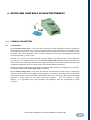
Continuing education is a very important aspect of healthcare delivery. Many excellent resources are available
today to expand the user's knowledge of many aspects of electrical stimulation therapy. BTL recommends a
thorough review of this guide prior to operating the equipment.
GENERAL EFFECT OF ELECTROSTIMULATION | Page 5 of 39
2 CLASSIFICATION OF ELECTROTHERAPEUTIC CURRENTS
2.1
GALVANIC CURRENT
Galvanic current (or “continuous”) is current of constant intensity. It is always DC. It is used mostly for
iontophoresis, or its trophic stimulating (hyperaemic) effect is utilized. A great disadvantage of galvanic current is
the risk of chemical damage to the tissue under the electrodes. The damage may be caused by the hydrochloric
acid which originates under the anode or by the soda lye which originates under the cathode. A similar danger of
tissue damage can also occur with any direct current (e.g. diadynamic).
Direct currents must not be used on patients with metallic implants!
At present, this current is often substituted by galvanic intermittent current. This current has the same effects
(galvanic component is 95 %) but thanks to interrupting the originally continuous intensity by the frequency 8 kHz,
it is better tolerated by patients. It is suitable especially for iontophoresis.
2.2 PULSE DIRECT CURRENT
Pulse direct current is current of variable intensity but with only one polarity. The basic pulse shape may vary. It
includes e.g. diadynamics (combination of pulse DC – "dosis" and galvanic current – "basis"), rectangular
(e.g. Träbert current), triangular and exponential pulses of one polarity.
Depending on the used frequency and intensity, it has stimulating, trophic and analgesic effects. Generally, direct
current with variable intensity has the same risks as galvanic current (corrosion of the skin surface) and therefore
requires careful observance of the correct procedure, especially the correlation between the applied intensity and
the length of application.
The main effect is stimulation, which is important especially below the cathode (green negative electrode).
2.3
ALTERNATING CURRENT
In comparison with DC, alternating current is safer and better subjectively tolerated by the patient. The basic
pulse shape again may be various – rectangular, triangular, harmonic sinusoidal, exponential or combined. It can
be alternating, symmetric or asymmetric. The DC component is always zero, which prevents chemical damage of
the skin under the electrodes.
Therefore, this current also allows long-term applications, even for patients with metal implants. Implanted
electronic stimulators such as pacemakers, etc. are indeed quite contraindicated. Nowadays, low-power pulses –
TENS (Transcutaneous Electrical Nerve Stimulation) and interference – are gaining ground among alternating
currents. Use of alternating currents in contact electrotherapy implies much lower stress on the tissue under the
electrode.
For these types of current, the capacitive component of skin resistance is involved, and also thanks to it these
currents are very well tolerated by patients.
CLASSIFICATION OF ELECTROTHERAPEUTIC CURRENTS | Page 6 of 39
In general:
2.3.1
•
short duration of the pulse improves the subjective perception,
•
the zero average value (DC component) prevents chemical damage of the tissue,
•
frequency and amplitude are responsible for the required therapeutic effect.
TENS
TENS = transcutaneous electrical nerve stimulation
Nowadays, a very prevalent group of currents which substitutes the standard applications of diadynamic currents,
Russian stimulation, etc. TENS pulses are low power and have zero DC component. Therefore, besides
suppression of chemical damage of the tissue, the risk of electrical damage of the tissue is also minimized.
As can be seen from their name, these currents are intended for the stimulation of nerve stems or nerve fibres.
Their major utilization is in the alleviation of pain, inhibition of itching, etc. The mechanism of their effect is most
often explained by the so-called gate theory of pain. Besides treating pain, these currents can also be effectively
utilized in electrogymnastics (stimulation of non-denervated muscles).
2.3.2
CLASSIC (FOUR-POLE) INTERFERENCE
Four electrodes are located crosswise. Two frequency signals with different frequencies fA and fB are brought to
the tissue. Their interference in the tissue induces a low-frequency surge in the centre of the cross; its frequency
is:
AMF = fA - fB.
This surge of the frequency AMF has a therapeutic effect; both basic currents of the frequency fA and fB are used
only for "transport" of the AMF surges to the tissue. The fA frequency is constant; changes in the fB frequency by
the value of the so-called Spectrum serve to change the resulting frequency AMF to the frequency
AMF + Spectrum. Interference has similar effects as low-frequency currents although it is carried by a current of
higher frequency and does not stress the tissue under the electrode so much. The carrier frequency of channels
ranges from 3.5 to 10 kHz. The higher this frequency, the better it is tolerated by the patient. The advantage of
four-pole interference is the in-depth aiming of the treated area and lower stress on the superficial skin. Therefore,
higher intensity values can be set than for the two-pole application.
2.3.3
TWO-POLE INTERFERENCE
According to the new recommended terminology, these groups should be called "bipolar-applied
amplitude-modulated mid-frequency currents"; however, owing to the length of this name, we are keeping to the
original one.
The resulting low-frequency current of the frequency AMF (or AMF + Spectrum) is created by the equipment.
Therefore, two electrodes are sufficient for its application. The absolute intensity values that can be reached are
lower than in classic interference (this current is more poorly tolerated by the patient than classic interference)
and at the same time the stress on the skin surface is higher than in classic interference.
Its advantage is that it can be applied by point electrode and thus can be effectively used in combination with
therapeutic ultrasound.
2.3.4
ISOPLANAR INTERFERENCE
A special form of four-pole interference where the additional modulation of both channels enables the treated area
to be distributed to the whole space of the current circuits’ interlacement. This implies that placing of individual
electrodes is much easier – they do not need to form a perfect cross anymore. The effect of these currents is very
diffuse, in-depth and delicate.
CLASSIFICATION OF ELECTROTHERAPEUTIC CURRENTS | Page 7 of 39
2.3.5
DIPOLE VECTOR FIELD
Additional phase and amplitude modulation of the basic signals of four-pole interference enables only one
direction of the electric field’s action to be achieved (a so-called dipole is created in the tissue). In the direction of
this dipole, the modulation of the field reaches up to 100 %, in the other directions it is almost zero. You can either
rotate this dipole (abscissa) manually, and thus precisely aim the required effect of the therapy at the treated
tissue, or let it rotate automatically.
CLASSIFICATION OF ELECTROTHERAPEUTIC CURRENTS | Page 8 of 39
3 EFFECTS OF ELECTROTHERAPY
3.1
ANALGESIC EFFECT
Pain is a multi-factor phenomenon and practice positively shows that various types of pain respond more or less
well to various physiotherapeutic, i.e. also electrotherapeutic procedures. There are several mechanisms of the
analgesic effect of electrotherapy – besides the well-known gate theory of pain there is also a proven increase in
the production of endogenous opiates. The analgesic effect is also supported by the trophic effects of the flowing
current. Timely myorelaxation removes muscular hypertone and thus also pain of myofascial origin. Since the
analgesic effect of electrotherapy is fundamental and most utilized, it shall be described in a little more detail.
Pain is usually simply defined as an unpleasant sensory and emotional experience connected with actual or
potential damage of tissue. We usually distinguish between acute and chronic pain. Acute pain is short-lasting
(maximum several days or weeks). It is caused by mechanical damage of the tissue or by a disease, comes
immediately after a painful stimulus and subsides when it ends; the intensity of pain depends on the intensity of
the stimulation. On the other hand, chronic pain is long-lasting (more than 3 months) or it recurs; its intensity does
not depend on the intensity of stimulation; emotions particularly play a leading role.
The now generally accepted theory of perception of pain is based on the assumption of the existence of a specific
sensory system which transfers information from pain receptors (nociceptors) to the central nervous system by
special preformed nerve paths. However, the process is in fact much more complicated and those interested can
learn about it in the available specialized literature.
To understand the effects of electrotherapy, it is important to understand especially the modulation factors which
can influence the perception and transfer of the painful stimulus:
•
The first crucial modulation factor is described by the so-called gate theory of pain, which is based on the
presumption that the nervous mechanism in posterior medullary horns act as a small gate which lets through
only a limited flow of nervous impulses from the peripheral afferent fibres to the central nervous system,
depending on how much it is opened. Stimulation of some particular fibres can modulate the extent of the
gate’s opening or closing for pain and thus also increase or decrease the transfer of nociceptive information.
A similar gate system is supposed to exist also on the level of the thalamus.
•
The other important modulation factor is described by the neuromodulation theory, which is based on the
analgesic effect of some substances belonging to the group of so-called neuromodulators, especially
endorphins and encephalins. These substances are produced in the central nervous system and according to
the mentioned theory they have crucial importance especially in the subjective perception of pain.
In any case, the analgesic effect of electrotherapy is used most often. To make PT of real benefit to the patient, it
is necessary to observe the following principles:
•
Do not suppress the signalling and protective function of pain (which is especially important in acute pain!),
i.e. first decrypt the information being signalled by the pain, properly determine the diagnosis or at least a
preliminary hypothesis, and only then intervene against the pain. Pain modified by PT or analgesics can lose
its specificity insomuch that later it cannot be decrypted.
•
Together with the application of analgesic PT, it is necessary to considerably reduce the administration of
analgesics. This rule is very important, owing to the possibility of relatively precise focusing of the analgesic
effect of PT (in contrast to the unfocused effect of medicaments) and possible undesired interaction between
PT and the medicaments.
•
When choosing the type of PT, consider the expected effect (gate theory, endorphins).
EFFECTS OF ELECTROTHERAPY | Page 9 of 39
•
For chronic or recurrent complaints, do not obstinately apply various types of PT, but examine the locomotive
system (or get it examined by a specialist) – very often, the source of these complaints is far from the place
of projection of pain (catenation-generalization).
For the stimulation of thick, myelinized nerve fibres of A beta and delta types (gate theory), it is suitable to use
low-frequency currents of frequency 50 - 150 Hz (optimum 100 Hz) and intensity at or above threshold sensitivity.
This method is effective especially for acute and segmentally localised pains. For painful chronic syndromes, it is
most suitable to use low frequencies of 2 - 8 Hz and intensity at the highest tolerable level (up to the threshold of
pain); thus, thin fibres of the C type are stimulated (creation of endorphins). To achieve a combination of both
above-stated mechanisms of easing pain, use "burst modulation". The carrier frequency should be about 100 Hz,
burst frequency up to 10 Hz (even frequencies lower than 1 Hz are not exceptional). Currents with burst
modulation bring a cumulated analgesic effect. According to the depth of the required effect, the procedures can
be ordered as follows (from the most superficial to the deepest ones):
3.2
•
analgesic effect of anelectrotonus (galvanic current)
•
diadynamic currents LP and CP-ISO
•
Träbert current
•
TENS
•
2-pole interference (amplitude-modulated mid-frequency currents),
•
4-pole interference, isoplanar interference and vector fields
MYORELAXATION AND SPASMOLYTIC EFFECT
Especially after posturographic examination had proved that overall administration of so-called myorelaxancies
has a negative long-term influence on the body posture, the possibility of exact aiming at the hypertonic muscle
has been regarded as an especially valuable advantage of myorelaxation procedures. In the overall application of
myorelaxancies, there are first affected the phasic muscles, which have been already weakened due to the layer
syndrome. Later, or when a stronger dose is applied, there are also affected the tonic muscles and only at the
end, at the strongest dosage, are hypertonic muscles also positively affected. This effect lasts for several weeks
and affects the structure of the spine very negatively even after acute complaints have subsided.
Procedures with myorelaxation effect include therapeutic ultrasound, 2-pole interference with contour frequency
100 – 200 Hz, 4-pole interference currents and high-voltage therapy in the same frequency modulation band. For
small superficial muscles especially in the hands, paraffin can also be used.
A favourable side effect of myorelaxation is also the analgesic effect.
3.3
TROPHIC EFFECT
is caused by hyperaemia, which occurs in almost all types of PT (except cryotherapy). Since the mechanism of
hyperaemia in various types of PT is different, it is necessary to take these mechanisms into account so as to be
able to select the particular PT. Generally, galvanization can be recommended, especially longitudinal (capillary
hyperaemia, vessel eutonisation), low-frequency currents of frequency 30 - 60 Hz and intensity at or above the
threshold motor activity level (muscle micropump) or ultrasound, laser, polarized specified achromatic light,
vacuum-overpressure therapy, etc.
The trophic effect may be partly caused by the fact that most forms of PT, esp. laser, biolamp and
magnetotherapy, bring energy into the organism, to be used by cells (or other structures) for their activity.
The trophic hyperaemic effect is also usually connected with the analgesic effect.
EFFECTS OF ELECTROTHERAPY | Page 10 of 39
3.4
ANTIEDEMATOUS EFFECT
is practically connected with hyperaemia, vessel eutonisation and higher capillary permeability. Therefore, the
therapies referred to as trophic are also antiedematous (see the previous paragraph).
3.5
PLACEBO EFFECT
Opponents of physical therapy tend to refer to its effects as placebo.
If PT is applied accidentally, without knowledge of its mechanism, accurate aiming and dosage (as often
happens), its effects can be called this. Exact verification of the effects of PT faces many problems.
3.6
•
Owing to the fact that lege artis application of PT requires especially the patient's individuality and momentary
functional status to be taken into account (including the limbic system status, mood, muscular tonus, season
of the year, weather, motivation, attitude to problems, etc.) it is almost impossible to create a group for further
statistical processing. Creation of a control group is practically out of question.
•
The effect of PT lies almost only in affecting the afferent system. The afferent system processes all data,
including visual, auditory, tactile and other analysers. Since a slight stimulus is very often sufficient to deviate
the organism from the existing functional balance (even pathological) and, using its enormous self-repairing
abilities, the organism helps itself, there cannot be carried out e.g. a blind experiment without at least
minimum excitation of the afferent system and/or higher components of CNS.
•
Functional defects of the locomotive organs, which are the main positive effects of PT, tend to self-repair if
they are not prevented from that (e.g. by inappropriate pharmacotherapy). If correctly indicated, PT both
initiates and accelerates this self-repair, which indeed can be hardly proved exactly.
DEFERRING EFFECT
A "troublesome" patient is often invited for a check-up only after undergoing usually ten procedures and "hopefully
will be better then". This way of thinking is immoral, unethical and discreditable to a specialist, but nevertheless
most of the existing prescriptions of PT unfortunately belong to this category. In some surgeries patients are even
told that the effect of the chosen PT will become apparent only after several months (!), which means that the
physician fully relies on the body’s self-repair abilities.
Indication of PT should then not be based only on the diagnosis, especially if the diagnosis is confusing, e.g.
periarthritis humeroscapularis, etc.
The attending physician should know the answers to the following questions:
•
What is the cause of the complaints, i.e. usually pain?
•
Is the defect functional or organic?
•
Where was the defect initiated – where is (are) the key area(s)?
•
Which of the above-mentioned effects of PT is the most important for the patient at the moment?
•
Is there not a risk of aggravation or organification of the functional defect after the chosen PT?
With the answers, the physician should choose the type, location, intensity, frequency and total number of
treatments, and, in relation to them, also the date of the check-up of the patient.
EFFECTS OF ELECTROTHERAPY | Page 11 of 39
3.7
3.8
CONTRAINDICATIONS FOR ELECTROTHERAPY
•
active TB
•
allergy to the solutions used for moistening the electrode sponge covers
•
application in the area of the heart or eyes
•
pacemaker
•
cardiovascular diseases
•
cochlear implants
•
metal implants and/or malignancies in the current path
•
skin defects and inflammations
•
bleeding
•
menstruation
•
tumours
•
defects of sensitivity at the site of the electrode
•
psychopathological syndromes and organic psychosyndromes
•
multiple sclerosis
•
pregnancy
•
inflammations of the veins and lymphatic paths
SYMBOLS OF EFFECTS A-E-T-R-S
Symbols of the effects of therapy used in the equipment have the following meaning:
A
-
analgesic
E
-
antiedematous
T
-
trophic
R
-
myorelaxation
S
-
stimulation
EFFECTS OF ELECTROTHERAPY | Page 12 of 39
4 SETUP AND CONTROLS OF ELECTROTHERAPY
4.1
4.1.1
COMMON PARAMETERS
OUTPUT MODE
CC (= constant current) mode – in this mode, the current flowing through the patient is constant, regardless of
the impedance of the patient's tissue. Owing to physiological effects during electrotherapy, the impedance of the
tissue decreases, which in the normal course of events causes spontaneous rise in the current flowing through
the patient, which can be unpleasant. The CC mode is therefore useful for most static applications with fixed
electrodes (including e.g. suction cups).
However, if you want to use point electrodes, combined therapy with ultrasound head, moving electrodes
(e.g. roller), etc., it is suitable to switch over to the constant voltage mode because moving the electrode in the
current mode causes a temporary reduction in the contact area between the electrode and the patient's skin and
consequently a significant rise in the current density, which could be painful for the patient.
Similarly for therapies where muscle contractions are expected and/or electrodes could slightly move on the skin,
it is suitable to select the constant voltage mode of stimulation.
CV (= constant voltage) mode – in this mode, the voltage on the electrodes is constant. Owing to physiological
effects, the current in the tissue may slightly rise during therapy and therefore it is usually necessary to adjust the
set intensity according to the patient's feelings, approximately every one or two minutes. Still, this mode is suitable
especially in cases where the CC mode would bring problems – pain and reduction in output
intensity – i.e. in applications with moving electrodes and applications which are accompanied by muscle
contraction.
SETUP AND CONTROLS OF ELECTROTHERAPY | Page 13 of 39
4.1.2
POLARITY
•
positive polarity:
socket marked "+" is anode (use the cable
with
red banana
plugs)
socket marked "-“ is cathode (use the cable with white or black banana plugs)
•
negative polarity:
the polarity of sockets is reversed ("+" = cathode; "-" = anode)
•
positive, reversal:
the first half of therapy has positive polarity of the signal, in the middle of therapy
the polarity automatically changes to negative
•
negative, reversal:
•
pos., rev. with interrupt.: the first half of therapy has positive polarity of the signal, in the middle of therapy
the first half of therapy has negative polarity of the signal, in the middle of therapy
the polarity automatically changes to positive
the polarity automatically changes to negative; during the change, the equipment
interrupts therapy and waits for re-setting of the correct intensity
•
4.1.3
neg., rev. with interrupt: the first half of therapy has negative polarity of the signal, in the middle of therapy
the polarity automatically changes to positive; during the change, the equipment
interrupts therapy and waits for re-setting of the correct intensity
THERAPY TIME
Can be set within a range from 00:01 to 99:59 [min:sec].
4.1.4
PHYSIOLOGICAL EFFECTS
Characterize particular diagnoses and programs and can be adjusted. For the meaning of particular symbols, see
the chapter Symbols of Effects A-E-T-R.
4.2
4.2.1
TENS
TYPE
symmetric – the positive pulse is immediately followed by the negative one
alternating – the positive pulses regularly alternate with the negative ones
asymmetric – positive rectangular pulses are followed by exponential pulses of negative polarity.
Nowadays, the most widespread type of TENS, probably because of its favourable effects which
are similar to those of DC pulses, and electrochemical properties corresponding to AC.
4.2.2
PULSE, FREQUENCY, PAUSE
In this dialog box, it is possible to set basic parameters of the
generated TENS – TENS pulse length, pause between TENSes or
TENS frequency. All these three parameters are mutually related
by the following mathematical relations and therefore during
change in one parameter, the other ones can change, too:
SETUP AND CONTROLS OF ELECTROTHERAPY | Page 14 of 39
symmetric TENS:
frequency = 1 000 000 / (2 * pulse + 1000 * pause) [Hz; µs, ms]
alternating TENS:
frequency = 1 000 000 / (2 * pulse + 2000 * pause) [Hz; µs, ms]
asymmetric TENS:
frequency = 1 000 000 / (7 * pulse + 1000 * pause) [Hz; µs, ms]
Note: The relations are based on the electric waveform of TENS and the manner of their generation.
4.2.3
ELECTRO PARAMETERS
For details, see the chapter Pulse Modulation.
4.3
4.3.1
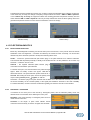
2-POLE, 4-POLE, ISOPLANAR AND DIPOLE INTERFERENCE
CARRIER FREQUENCY
Frequency of the "carrier" which "transports" to the tissue (for two-pole interference) or creates in the tissue (for
four-pole interference) a low-frequency therapeutic surge.
I [mA]
t [s]
Carrier frequency (high frequency)
Frequency of therapeutic surges (low frequency)
4.3.2
ELECTRO PARAMETERS
For details, see the chapter Interference – Parameters.
Isoplanar Interference – "Field Rotation"
Isoplanar vector field is a special form of four-pole interference where amplitude modulation of both
channels causes even, almost 100 % modulation in the entire area of the current circuits
intersection. The nature of these regular amplitude changes of channels corresponds to "rotation"
of the whole field. This parameter should best be set to the value which equals the entire sweep
time (for the continuous and jump sweep, it is the sum of all set times, for the symmetric sweep set,
the rotation time equal to the sweep time).
Dipole Interference – Dipole Rotation
For the dipole vector field with automatically rotating dipole, you can set the speed of rotation of this
dipole in the area of the intersection of current circuits.
In the direction of the dipole, the depth of modulation is always maximum; in the other directions it
is minimum.
SETUP AND CONTROLS OF ELECTROTHERAPY | Page 15 of 39
4.4
4.4.1
RUSSIAN STIMULATION
CARRIER FREQUENCY
Frequency of the "carrier" which "transports" low-frequency
therapeutic pulses to the tissue – similarly as for two-pole
interference, where the carrier transports low-frequency surges there.
4.4.2
PULSE FREQUENCY, DF
In this dialog box it is possible to set the frequency of
low-frequency pulses.
DF (duty factor) parameter is the ratio of the pulse length to the
length of the pause between pulses.
4.4.3
PULSE LENGTH (ELECTRO PARAMETERS)
In this dialog, which is similar to that for setting trapezoid surges – see the chapter Trapezoid Surges, it is
possible to set the rise time of the amplitude of low-frequency currents, duration of stimulation, fall time and
duration of relaxation.
4.5
MID-FREQUENCY SURGES
These stimulation pulses are in principle similar to Russian stimulation but have a wider range of possible
individual settings.
4.5.1
CARRIER FREQUENCY
See the previous chapter Carrier Frequency.
4.5.2
PULSE, FREQUENCY, PAUSE
In this dialog box, it is possible to set the basic parameters of
generated pulses – length of pulse of the mid-frequency surge,
pause between pulses and pulse frequency. All these three parameters are mutually related by the following
mathematical relation and therefore during change of one parameter, the other ones can change, too:
frequency = 1 000 / (pulse + pause) [Hz; ms, ms]
The limits of setting individual parameters are determined by the carrier frequency.
4.5.3
ELECTRO PARAMETERS
The parameters to be set are the same as for most basic stimulation pulses. For details, see the chapter Pulse
Modulation.
SETUP AND CONTROLS OF ELECTROTHERAPY | Page 16 of 39
4.6
4.6.1
DIADYNAMIC CURRENTS
TYPE
The basic types of diadynamic currents are as follows:
DF: basic diadynamic pulses of frequency 100 Hz or 120 Hz – "two-wayrectified mains frequency" (according to the mains frequency 50 / 60 Hz)
MF: basic diadynamic pulses of frequency 50 Hz or 60 Hz – "one-wayrectified mains frequency" (according to the mains frequency 50 / 60 Hz)
CP: diadynamic pulses created by combination of types DF and MF, the
pulses alternate every 1 second for basic frequency 50 Hz and every 1.2
second for basic frequency 60 Hz
CP-ISO: the same combination of pulses DF and MF, but the mutual
intensity of currents is equalized by the base-line (owing to the difference in
perception of DF and MF, intensity of the MF current is 11 % lower than that
of the DF current)
LP: diadynamic current with smooth transitions between DF and MF surges.
The whole change of the MF surge to DF and back to MF lasts 10 or 12
seconds and the length of the MF surge is 6 or 7.2 seconds (according to
basic frequency 50 Hz / 60 Hz)
RS: diadynamic current combined of the MF current (time 1 or 1.2 second)
and a pause (length 1 or 1.2 second – according to basic frequency
50 / 60 Hz)
4.6.2
BASE
To the pulse component of the diadynamic current there is added the galvanic component – base. It can be
defined proportionally – the base component represents the set percentage of the total intensity.
4.6.3
ELECTRO PARAMETERS
Basic Frequency
Basic frequency which the diadynamic pulses are derived from. It is based on the frequency of the mains – for
countries with mains frequency 50 Hz (Europe, Asia), set the option 50 Hz / 100 Hz; for countries with mains
frequency 60 Hz, you can use the option 60 Hz / 120 Hz. You can select the option according to your practice, but
please note that the original basic frequency of diadynamic currents was 50 Hz (these currents were discovered
accidentally by the dentist Bernard in France – see PODĚBRADSKÝ, J., VAŘEKA, I. Fyzikální terapie I.. Praha:
Grada, 1998.)
Interruption
This option switches on the "momentary interruption" of the generated
waveform. The length of the interruption is 5 µs and the repeating frequency
of interruption is 8000 Hz. As for power, there is no change in the generated
waveform (duty factor is 96 %) but the patient's tolerance is higher.
SETUP AND CONTROLS OF ELECTROTHERAPY | Page 17 of 39
4.7
4.7.1
PULSES: RECTANGULAR, TRIANGULAR, EXPONENTIAL
EXPONENTIAL RISE, COMBINED, INTERRUPTED
AND
TYPE
monophasic – pulses of only one polarity (ATTENTION! These pulses have galvanic effect!)
symmetric – the positive pulse is immediately followed by the negative one
alternating – the positive pulses regularly alternate with the negative ones
asymmetric, combined - positive rectangular pulses are followed by exponential pulses of
negative polarity. Their effects are similar to those of DC pulses but the electrochemical properties
correspond to AC.
4.7.2
PULSE, FREQUENCY, PAUSE
In this dialog box it is possible to set the basic parameters of generated
pulses – pulse length, pause between pulses and pulse frequency. All
these three parameters are mutually related by the following
mathematical relations and therefore during change of one parameter,
the other ones can change too:
monophasic pulses:
frequency = 1 000 / (pulse + pause) [Hz; ms, ms]
symmetric pulses:
frequency = 1 000 / (2 * pulse + pause) [Hz; ms, ms]
alternating pulses:
frequency = 1 000 / (2 * pulse + 2 * pause) [Hz; ms, ms]
asymmetric pulses:
frequency = 1 000 / (pulse + 7 * pause) [Hz; ms, ms]
Note: The relations are based on the electrical waveform of the pulses and the manner of their generation.
4.7.3
ELECTRO PARAMETERS
For details, see the chapter Pulse Modulation.
SETUP AND CONTROLS OF ELECTROTHERAPY | Page 18 of 39
WITH
4.8
4.8.1
STIMULATION PULSES
TYPE
The two basic types suitable for stimulation are rectangular and triangular.
4.8.2
PULSE, PAUSE
The setup dialog is similar to that in the previous chapter Pulse, Frequency, Pause, but it is possible to set only
the pulse length and pause length.
For correct stimulation by individual pulses, it is recommended to maintain the following relation:
tPAUSE = 0.003 * tPULSE
4.8.3
[s; ms]
ELECTRO PARAMETERS
Sound Signal
The sound signal indicates the moment of generation of the stimulation pulse. Possible settings:
beep – the length of the beep corresponds to the length of the generated pulse
click – a short "click" indicates the beginning of the generated pulse
no sound.
4.9
TRÄBERT CURRENT, LEDUC CURRENT, FARADIC CURRENT, NEOFARADIC
CURRENT, H-WAVES
Special types of pulse currents, for their parameters, see the chapter Technical Parameters.
4.10 GALVANIC CURRENT
4.10.1
TYPE
Continuous or interrupted. The length of interruption is 5 µs, repeating frequency is 8000 Hz.
SETUP AND CONTROLS OF ELECTROTHERAPY | Page 19 of 39
4.11 MICROCURRENTS
are designed for application by tip or point electrode.
4.11.1
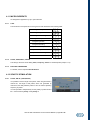
TYPE
The waveforms of the particular current types are best illustrated in the following table:
rectangular monophasic
rectangular symmetric
rectangular alternating
triangular monophasic
triangular symmetric
triangular alternating
exponential monophasic
exponential symmetric
exponential alternating
combined
4.11.2
PULSE, FREQUENCY, PAUSE
This dialog is the same as the dialog Pulse, Frequency, Pause for standard pulses (chapter 4.7.2).
4.11.3
ELECTRO PARAMETERS
For details, see the chapter Pulse Modulation.
4.12 SPASTIC STIMULATION
4.12.1
PULSE, DELAY, (FREQUENCY)
It is possible to set the length of T1 pulses, which are generated by
channel E1, the length of T2 pulses, which are generated by
channel E2, the delay between pulses T1 and T2 and the repeating
frequency of pulses.
It is also possible to independently set the polarity of pulses T1 and
T2 – see the buttons polarity 1 and polarity 2.
SETUP AND CONTROLS OF ELECTROTHERAPY | Page 20 of 39
4.13 PULSE MODULATION
4.13.1
CONSTANT FREQUENCY
The set current has no supplementary modulation and is not further
influenced. See the picture – rectangular pulses.
4.13.2
RANDOM FREQUENCY
During generation, the frequency of the generated current randomly
changes within a range of approx. ± 30 %. See the picture with
random "compression" of rectangular pulses.
4.13.3
BURST
Low-energy group of several pulses following immediately one after
the other. It is possible to set the number of pulses in burst and
frequency of bursts [Hz]. For information, there is calculated the pause between bursts [ms] and burst length
[ms]. It is also possible to choose from several pre-defined values.
4.13.4
SINE SURGES
High-energy group of pulses which can cause e.g. a muscle
contraction. It is possible to set the sine surge length [s]
(= stimulation time) and pause between surges [s] = relaxation
time.
It is also possible to choose from several pre-set values.
4.13.5
TRAPEZOID SURGES
High-energy group of pulses which can cause e.g. a muscle
contraction. It is possible to set the trapezoid surge rise time
[s] = time of rise of stimulation, stimulation time [s], trapezoid
surge fall time [s] = subsiding of stimulation, and pause
between surges [s] = relaxation time.
It is also possible to choose from several pre-set values.
4.13.6
SYMMETRIC SURGES
High-energy group of pulses which can cause e.g. a muscle
contraction. It is actually a symmetric trapezoid surge with a
different way of setting. It is possible to set the sweep time [s]
– i.e. the stimulation and relaxation time, always including rise
(or fall) time, and the so-called contour [%] – i.e. the ratio between
the actual stimulation time and the stimulation rise time. It is
possible to choose from several pre-set values.
SETUP AND CONTROLS OF ELECTROTHERAPY | Page 21 of 39
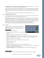
4.14 INTERFERENCE – PARAMETERS
4.14.1
AMF AND SPECTRUM
AMF is the basic frequency of therapeutic surges which is created in the tissue by interference (e.g. by a
combination of the signal of channel E1 with the signal of channel E2). This applies for four-pole interference. For
two-pole interference, the surges of the basic frequency AMF are directly "transported" to the tissue by the carrier.
Spectrum determines the extent of change of the basic frequency of therapeutic surges – AMF. The resulting
I [mA]
t [s]
Carrier frequency (high frequency)
Frequency of therapeutic surges (low frequency)
frequency of therapeutic surges then ranges from AMF to AMF + Spectrum and changes according to the set
way of frequency sweep.
4.14.2
FREQUENCY SWEEP
defines the ways of sweep of the resulting frequency of therapeutic surges between AMF and AMF + Spectrum:
•
continuous (rise of frequency, upper hold, fall and lower hold)
•
continuous, random
•
in jumps (upper and lower hold)
•
in jumps, random
•
symmetric (time of change = "sweep time", "contour")
•
symmetric, random.
The differences between particular ways of sweep are displayed in the following pictures:
SETUP AND CONTROLS OF ELECTROTHERAPY | Page 22 of 39
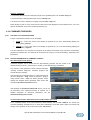
The difference between standard and random way of sweep is again best illustrated in the following two pictures.
In the classic way of sweep, the change of frequency always involves two values – AMF and AMF + Spectrum.
In the random way of sweep, the equipment selects the resulting generated frequencies randomly from the
values between AMF and AMF + Spectrum. This way of sweep reduces the risk of the tissue getting used to the
generated frequencies and thus in some cases it increases the success of therapy:
standard sweep
random sweep
4.15 ELECTRODIAGNOSTICS
4.15.1
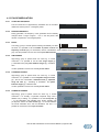
MOTOR POINT DETECTION
Before any electrodiagnostic measuring, first find the motor point of the muscle, i.e. the point at which the muscle
stimulation is the most significant – contraction is initiated by the lowest set value of intensity. You should also
determine by which electrode (cathode or anode) the measuring will be done.
Anode – connect the positive electrode (red banana plug) to the plate electrode as a reference electrode.
This electrode shall be placed proximally or distally to the treated muscle. It is also possible to use a suction cup
electrode – continuous vacuum mode.
Cathode – the negative electrode (black banana plug) is
connected to the stimulation point electrode.
To find the motor point, it is recommended to use pulses of length
approx. 5 ms for healthy muscle and approx. 100 ms for
denervated muscle. The pause between pulses should be 2 - 3
seconds. After finding the motor point, reverse the polarity of the
output current (positive polarity → negative, or shift the
electrodes – red banana plug to the point electrode and the black one to the reference electrode) and measure
the muscle sensitivity for the reversed polarity of the signal (the stimulation electrode in this case is anode).
For further stimulation, use that connection of electrodes (polarity) for which the muscle is more sensitive.
4.15.2
RHEOBASE – CHRONAXIE
is measured in the motor point of the muscle by rectangular pulses, with the electrode polarity which was
determined as more sensitive when detecting the motor point.
Rheobase is the lowest intensity of rectangular pulse current to
initiate muscle contraction.
Chronaxie is the length of pulse which initiates muscle
contraction and the intensity of which is 2x higher than rheobase.
SETUP AND CONTROLS OF ELECTROTHERAPY | Page 23 of 39
The values of rheobase and chronaxie can be determined from the completely measured I/t curve – see the
chapter I/t Curve, or can be measured by the following simplified method.
First measure the rheobase (length of the measured pulse is 1000 ms) and then the chronaxie. The equipment
automatically sets the correct intensity of the measuring pulse – you set its length (by the time / stop knob: turn it
to set the pulse length, press it to start or stop the stimulation). After finding both values, save the measured
results.
It is recommended to write in the note whether the stimulation point electrode was cathode or anode.
4.15.3
ACCOMMODATION COEFFICIENT
is measured at the motor point of the muscle by a triangular and a rectangular pulse, with the electrode polarity
which was determined as more sensitive when detecting the motor point.
Accommodation coefficient is the ratio between the intensity of the triangular pulse and the intensity of the
rectangular pulse. Pulse width is 1000 ms and pause between pulses is 3 seconds. First measure the rectangular
pulse, after measuring and saving it by the time / stop knob (17), the equipment automatically switches to
measuring by the triangular pulse. The set intensity is displayed in the upper box on the screen; the lower box
displays the current measured value of the accommodation coefficient with verbal diagnosis.
It is recommended to write in the note whether the stimulation point electrode was cathode or anode.
4.15.4
I/T CURVE
is measured at the motor point of the muscle by a triangular or a
rectangular pulse, with the electrode polarity which was
determined as more sensitive when detecting the motor point.
I/t Curve – Options
This menu includes the following options:
•
edit point: to quickly and directly set the pulse length and
pause length
•
delete point: to delete the measured point of the curve from the graph
•
new curve - rectangular pulses: to add a new I/t curve to the graph to be measured by rectangular pulses
•
new curve - triangular pulses: to add a new I/t curve to the graph to be measured by triangular pulses
•
delete curve: to delete the curve from the graph
•
import curve: to load an I/t curve from the equipment's memory to the graph
•
save curve: to save the I/t curve
•
motor point detection
•
calculation of chronaxie-rheobase: active only if the graph displays just one curve
•
calculation of accommodation coefficient: active only if the graph displays two curves – one measured by
triangular pulses and the other by rectangular pulses
•
calculation of stimulation: active only if the graph displays two curves measured by triangular pulses
I/t Curve – Properties
On this screen, define the name of the I/t curve and supplementary information and assign it to the patient.
SETUP AND CONTROLS OF ELECTROTHERAPY | Page 24 of 39
I/t Curve – Measuring
To move along the time axis and change the length of the generated pulse, turn the time / stop knob.
To set the intensity of the generated pulse, turn the intensity knob.
To insert the set value of intensity to the graph, press the time / stop knob.
Plastic buttons >> and << on the screen serve to select which of the displayed I/t curves will be active – this curve
will then be dealt with in the menu and during measuring, etc.
4.16 COMBINED THERAPIES
4.16.1
POLARITY OF ULTRASOUND HEAD
Polarity of the ultrasound head is set on the display:
•
anode (+) – in this case, select on the display for generator E1 (or on the electrotherapy display) the
output polarity "positive“
•
cathode (-) – in this case, select on the display for generator E1 (or on the electrotherapy display) the
output polarity "negative"
The other electrode to be connected to the patient is the reference electrode of the respective electrotherapy
generator (as standard E1). This electrode is connected to the output (-) on the electrotherapy, preferably by the
black cable.
4.16.2
SETTING PARAMETERS OF COMBINED THERAPY
BTL-4000 Topline Combi Devices
Combined therapies can be started from the electrotherapy generator with the symbol of the
ultrasound head on its tab – see the picture. Usually, it is the electrotherapy generator E1.
Only the lists of this generator contain combined therapies,
including combined diagnoses, combined programs and
manual selection of therapy.
After selecting the combined therapy (no matter whether from
the list of diagnoses – diag, the list of programs – prog or
using manual control – man) the electro generator screen
displays the standard electro parameters setup screen with
the added "parameters ultrasound" button.
After pressing the "parameters ultrasound" button, you can set
all parameters of the ultrasound therapy as required. For a
detailed description of ultrasound parameters, see the
Ultrasound Therapy User's Guide.
Connected Devices BTL-4000 Topline Pulse and BTL-4000 Topline Sono
For a schematic drawing of the interconnection of these devices, see the User's Manual. The devices are
controlled separately, therapies are run on each device individually. On the BTL-4000 Topline Sono device start
therapy on the generator U1 and uncheck the option "with electro".
SETUP AND CONTROLS OF ELECTROTHERAPY | Page 25 of 39
4.17 SPECIFIC ELECTROTHERAPY SETTINGS
4.17.1
CHECK OF CONTACT OF ELECTRODES
Here it is possible to disable (or enable) the check of contact of the electrodes with the patient's body during
therapy. From the factory, this function is ON. We recommend disabling it only if you want to use electrotherapy
especially for motor stimulations.
4.17.2
MEASURING OF ELECTRODES
The electrodes which are applied to the patient's body during therapy are subject to ageing, which manifests itself
by gradual growth of their resistance up to a level where further use is impossible (the device keeps displaying the
message "bad contact of electrodes with the patient"). The usability time of the electrodes depends especially on
the used types of currents.
This function serves to check the quality of the electrodes. The check starts after pressing the "start/stop" button.
The current status of electrodes is displayed in the bottom part. After switching on, press the electrodes against
each other – then the device displays the text result.
SETUP AND CONTROLS OF ELECTROTHERAPY | Page 26 of 39
5 RECOMMENDATIONS FOR ELECTROTHERAPY
5.1
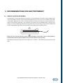
USE OF PLATE ELECTRODES
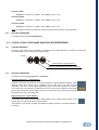
The equipment can work with plate BTL electrodes. For plate electrodes, use sponge covers moistened with
water (or therapeutic solution in case of iontophoresis). Before first use of the covers, it is necessary to rinse them
in tepid water. Moistening the covers or sponges prevents the patient from being burnt. When generating lowenergy currents (TENS), apply side 1 of the electrode in the sponge cover to the patient's body. One layer of the
sponge cover will be between the electrode and the patient's skin. For high-energy currents (recommended for all
currents except TENS), apply side 2 of the electrode in the sponge cover to the patient's body.
1
cover
electrode
2
Before first use, rinse the electrode sponge covers thoroughly in tepid water. They are impregnated by
the manufacturer with a special substance which prevents them from going mouldy.
After washing and drying, the electrode covers stiffen. It is not a defect – after moistening, they will become soft
again.
RECOMENDATIONS FOR ELECTROTHERAPY | Page 27 of 39
6 TECHNICAL PARAMETERS OF ELECTROTHERAPY
6.1
6.1.1
PARAMETERS OF PARTICULAR THERAPIES – CURRENTS
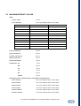
TENS
type:
symmetric, alternating, asymmetric
pulse:
10 to 400 µs
pause:
0.15 to 2 500 ms (depending on the pulse length, pulse type and
the set frequency)
frequency:
0.2 to 1 000 Hz (alternating)
0.4 to 1 000 Hz (symmetric, asymmetric)
see Modulation of Currents below
modulation:
6.1.2
6.1.3
4-POLE INTERFERENCE
carrier frequency:
3 600 to 10 000 Hz
AMF:
0 to 200 Hz
Spectrum:
0 to 200 Hz
frequency sweep:
see Frequency Sweep below
2-POLE INTERFERENCE
carrier frequency:
3 600 to 10 000 Hz
AMF:
0 to 200 Hz
Spectrum:
0 to 200 Hz
frequency sweep:
see Frequency Sweep below
TECHNICAL PARAMETERS OF ELECTROTHERAPY | Page 28 of 39
6.1.4
6.1.5
6.1.6
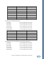
ISOPLANAR INTERFERENCE
carrier frequency:
3 600 to 10 000 Hz
AMF:
0 to 200 Hz
Spectrum:
0 to 200 Hz
frequency sweep:
see Frequency Sweep below
field rotation:
0.5 to 70 s
INTERFERENCE - DIPOLE VECTOR
type:
automatic, manual rotation
carrier frequency:
3 600 to 10 000 Hz
AMF:
0 to 200 Hz
Spectrum:
0 to 200 Hz
frequency sweep:
see Frequency Sweep below
dipole rotation:
from 3 rev. per second to 1 rev. per 30 seconds (auto-rotation)
RUSSIAN STIMULATION
carrier frequency:
2 500 to 10 000 Hz
pulse frequency:
40 to 150 Hz
pulse/pause ratio:
1:1 to 1:8 (exception; otherwise, the pulse/period ratio is used)
modulation:
trapezoid surges
(for parameters, see Modulation of currents below)
6.1.7
MID-FREQUENCY SURGES (AMPLITUDE-MODULATED)
carrier frequency:
2 500 to 10 000 Hz
pulse:
0.1 to 50 ms (depending on the set carrier frequency)
pulse frequency:
9.8 to 1 000 Hz (depending on the set carrier frequency)
modulation:
see Modulation of Currents below
TECHNICAL PARAMETERS OF ELECTROTHERAPY | Page 29 of 39
6.1.8
RECTANGULAR PULSES
type:
monophasic, symmetric, alternating
pulse:
0.2 to 1 000 ms
pause:
0.1 to 10 000 ms (monophasic, symmetric; then by the pulse length)
0.1 to 5 000 ms (alternating; then by the pulse length)
6.1.9
frequency:
0.1 to 1 000 Hz
modulation:
see Modulation of Currents below
TRIANGULAR PULSES
type:
monophasic, symmetric, alternating
pulse:
1 to 1 000 ms
pause:
0.1 to 10 000 ms (monophasic, symmetric; then by the pulse length)
0.1 to 5 000 ms (alternating; then by the pulse length)
frequency:
0.1 to 900 Hz (monophasic)
0.1 to 450 Hz (symmetric, alternating)
modulation:
6.1.10
see Modulation of Currents below
EXPONENTIAL PULSES, PULSES WITH EXPONENTIAL RISE
type:
monophasic, symmetric, alternating
pulse:
1 to 800 ms
pause:
0.1 to 10 000 ms (monophasic, symmetric; then by the pulse length)
0.1 to 5 000 ms (alternating; then by the pulse length)
frequency:
0.1 to 900 Hz (monophasic)
0.1 to 450 Hz (symmetric, alternating)
modulation:
see Modulation of Currents below
TECHNICAL PARAMETERS OF ELECTROTHERAPY | Page 30 of 39
6.1.11
6.1.12
COMBINED PULSES
type:
asymmetric
pulse:
0.2 to 1 000 ms
pause:
0.5 to 10 000 ms (depending on the pulse length)
frequency:
0.1 to 550 Hz
modulation:
see Modulation of Currents below
STIMULATION PULSES (FOR STIMULATIONS ACCORDING TO ELECTRODIAGNOSTICS)
type:
rectangular, triangular (monophasic)
pulse:
0.1 to 1 000 ms
pause:
0.5 to 10 s
pulse generation sound selection: no (beep depending on the pulse length)
6.1.13
INTERRUPTED PULSES
type:
rectangular, triangular (monophasic, symmetric, alternating)
interruption frequency:
8 000 Hz, duty factor 95 %
pulse:
1 to 30 ms
pause:
1 to 60 ms (monophasic)
1 to 30 ms (symmetric, alternating)
frequency:
11.1 to 500 Hz (monophasic)
11.1 to 333 Hz (symmetric)
8.3 to 250 Hz (alternating)
modulation:
see Modulation of Currents below
TECHNICAL PARAMETERS OF ELECTROTHERAPY | Page 31 of 39
6.1.14
6.1.15
6.1.16
6.1.17
TRÄBERT, ULTRA-REIZ 2-5
type:
monophasic
pulse:
2 ms
pause:
5 ms
frequency:
143 Hz
modulation:
see Modulation of Currents below
type:
monophasic
pulse:
1 ms
pause:
9 ms
frequency:
100 Hz
modulation:
see Modulation of Currents below
LEDUC
FARADIC, NEOFARADIC
type:
monophasic rectangular (faradic), monophasic triangular
(neofaradic)
pulse:
2 ms
pause:
20 ms
frequency:
45.5 Hz
modulation:
see Modulation of Currents below
type:
symmetric
pulse:
2 x 5.6 ms
pause:
0.22 to 10 000 ms
frequency:
0.1 to 87.7 Hz
modulation:
see Modulation of Currents below
H-WAVE
TECHNICAL PARAMETERS OF ELECTROTHERAPY | Page 32 of 39
6.1.17
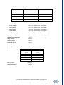
DIADYNAMICS
type:
DF, MF, CP, LP, RS, CP-ISO
base:
0 / 0.5 / 1 / 2 / 5 / 10 %
basic frequency:
50 or 60 Hz (the currents were derived from these frequencies)
pulse interruption:
8 000 Hz, duty factor 95 %
parameters of DF type*:
continuous sine pulses, frequency 100 Hz
parameters of MF type*:
continuous sine pulses, frequency 50 Hz
parameters of CP type*:
alternation of DF and MF: 1 second DF, 1 second MF
parameters of LP type*:
alternation of modulated DF (10 seconds) and MF (6 seconds)
parameters of RS type*:
alternation of MF and pause: 1 second MF, 1 second pause
parameters of CP-ISO type*:
alternation of DF and MF with amplitude 80 % of DF:
1 second DF, 1 second MF
DF
MF
CP
LP
RS
CPISO
* the parameters are defined for basic pulse frequency 50 Hz
TECHNICAL PARAMETERS OF ELECTROTHERAPY | Page 33 of 39
6.1.19
GALVANIC CURRENT (IONTOPHORETIC)
type:
6.1.20
continuous, interrupted by 8 000 Hz with duty factor 95 %
MICROCURRENTS
type:
rectangular, triangular, exponential (monophasic, symmetric,
alternating) and combined
pulse:
0.2 to 1 000 ms (rectangular, combined)
1 to 1 000 ms (other)
pause:
0.1 to 10 000 ms (monophasic, symmetric, combined; then by the
pulse length)
0.1 to 5 000 ms (alternating; then by the pulse length)
frequency:
0.1 to 1 000 Hz (rectangular)
0.1 to 700 Hz (combined)
0.1 to 900 Hz (other, monophasic)
0.1 to 450 Hz (other, symmetric and alternating)
6.1.20
modulation:
see Modulation of Currents below
note:
CC mode only
SPASTIC STIMULATIONS (ACCORDING TO HUFSCHMIDT)
pulses:
0.1 to 25 ms
delay between channels:
10 to 3 000 ms
frequency:
0.15 to 50 Hz (depending on the set pulse length and delay)
TECHNICAL PARAMETERS OF ELECTROTHERAPY | Page 34 of 39
6.1.22
HIGH-VOLTAGE THERAPY (HVT)
type:
single-peak, double-peak, triple-peak pulses
symmetric, alternating
20 µs (pulses: single, symmetric, alternating)
pulse:
30 µs (double-peak pulses)
40 µs (triple-peak pulses)
6.2
frequency:
0.1 to 500 Hz
modulation:
see Modulation of Currents below
note:
CV mode only
MODULATION OF CURRENTS
Types:
constant frequency
random frequency
burst
sine surges
trapezoid surges
symmetric surges
Random frequency:
standard ± 30 %
Burst (not designed for HVT):
number of bursts in a pulse:
3 to 10
frequency of bursts:
0.1 to 100 Hz (depending on length and freq. of pulses)
Sine surges:
surge length :
0.15 to 35 s (for HVT from 3 to 35 s)
pause length :
0.02 to 70 s (for HVT from 3 to 70 s)
Trapezoid surges:
rise, fall:
1 to 35 s
(for HVT from 3 to 35 s)
time of stimulation, pause between surges: 1 to 35 s
(for HVT from 3 to 35 s)
Symmetric surges:
sweep time:
1 to 35 s
contour:
1 to 99 %
(for HVT from 3 to 35 s)
TECHNICAL PARAMETERS OF ELECTROTHERAPY | Page 35 of 39
6.3
FREQUENCY SWEEP (INTERFERENCE)
types:
continuous, jump, symmetric
Random selection of frequency during yes/no
sweep:
Continuous sweep:
frequency rise and fall:
1 to 35 s
frequency hold:
0 to 35 s
Jump sweep:
frequency hold:
1 to 35 s
Symmetric sweep:
6.4
sweep time:
1 to 35 s
contour:
1 to 99 %
STEPS IN SETTING PARAMETERS
Steps in setting parameters of currents*
0.10 to 0.30:
0.01
0.30 to 1.00:
0.05
1.00 to 3.00:
0.10
3.00 to 10.0:
0.5
10.0 to 30.0:
1.0
30.0 to 100:
5
100 to 300:
10
300 to 1 000:
50
1 000 to 3 000:
100
3 000 to 10 000:
500
* applies for all settings except carrier frequency:
2 500 to 5 000:
100
5 000 to 10 000:
500
TECHNICAL PARAMETERS OF ELECTROTHERAPY | Page 36 of 39
6.5 MAXIMUM INTENSITY VALUES
TENS:
10 µs to 160 µs
140 mA
161 µs to 400 µs
140 mA (for additional limits, see the table)
pulse : pause
frequency 0.1 – 400 Hz
frequency above 400 Hz
100 : 1
50 mA
80 mA
10 : 1
52 mA
83 mA
5:1
54 mA
87 mA
2:1
61 mA
97 mA
1:1
70 mA
113 mA
1:2
86 mA
138 mA
1:3
100 mA
140 mA
1:5
122 mA
140 mA
1:7
140 mA
140 mA
1 : 10 to 1 : 10 000
140 mA
140 mA
2-pole interference:
140 mA
4-pole interference:
100 mA
Isoplanar interference:
100 mA
Dipole interference:
100 mA
Russian stimulation:
140 mA
Diadynamics: DF
70 mA
MF
100 mA
CP
80 mA
LP
80 mA
RS
100 mA
CP-ISO
80 mA
Rectangular pulses, combined pulses, interrupted rectangular pulses:
0.2 ms to 29 ms
140 mA (for additional limits, see the table)*
30 ms to 49 ms
110 mA (for additional limits, see the table)*
50 ms to 69 ms
90 mA (for additional limits, see the table)*
70 ms to 99 ms
80 mA (for additional limits, see the table)*
100 ms to 299 ms
70 mA (for additional limits, see the table)*
300 ms to 1000 ms
65 mA (for additional limits, see the table)*
TECHNICAL PARAMETERS OF ELECTROTHERAPY | Page 37 of 39
pulse : pause
frequency 0.1 – 400 Hz
frequency above 400 Hz
100 : 1
50 mA
80 mA
10 : 1
52 mA
83 mA
5:1
54 mA
87 mA
2:1
61 mA
97 mA
1:1
70 mA
113 mA
1:2
86 mA
138 mA
1:3
100 mA
140 mA
1:5
122 mA
140 mA
1:7
140 mA
140 mA
1 : 10 to 1 : 10 000
140 mA
140 mA
* the lower value is always valid
Triangular pulses, interrupted triangular pulses:
1 ms to 29 ms
140 mA (for additional limits, see the table)*
30 ms to 49 ms
110 mA (for additional limits, see the table)*
50 ms to 69 ms
90 mA (for additional limits, see the table)*
70 ms to 99 ms
80 mA (for additional limits, see the table)*
100 ms to 299 ms
70 mA (for additional limits, see the table)*
300 ms to 1000 ms
65 mA (for additional limits, see the table)*
pulse : pause
frequency 0.1 – 400 Hz
frequency above 400 Hz
100 : 1
71 mA
113 mA
10 : 1
74 mA
118 mA
5:1
77 mA
123 mA
2:1
86 mA
138 mA
1:1
100 mA
140 mA
1:2
122 mA
140 mA
1 : 3 to 1 : 10 000
140 mA
140 mA
* the lower value is always valid
Exponential pulses, pulses with exponential rise, interrupted exponential pulses:
1 ms to 29 ms
140 mA (for additional limits, see the table)*
30 ms to 49 ms
110 mA (for additional limits, see the table)*
50 ms to 69 ms
90 mA (for additional limits, see the table)*
70 ms to 99 ms
80 mA (for additional limits, see the table)*
100 ms to 299 ms
70 mA (for additional limits, see the table)*
300 ms to 800 ms
65 mA (for additional limits, see the table)*
TECHNICAL PARAMETERS OF ELECTROTHERAPY | Page 38 of 39
pulse : pause
frequency 0.1 – 400 Hz
frequency above 400 Hz
100 : 1
87 mA
138 mA
10 : 1
90 mA
140 mA
5:1
94 mA
140 mA
2:1
106 mA
140 mA
1:1
122 mA
140 mA
1 : 2 to 1 : 10 000
140 mA
140 mA
* the lower value is always valid
Stimulation pulses:
0.1 ms to 29 ms
140 mA (for additional limits, see the table)*
30 ms to 49 ms
110 mA (for additional limits, see the table)*
50 ms to 69 ms
90 mA (for additional limits, see the table)*
70 ms to 99 ms
80 mA (for additional limits, see the table)*
100 ms to 299 ms
70 mA (for additional limits, see the table)*
300 ms to 1000 ms
65 mA (for additional limits, see the table)*
Träbert current (Ultra-Reiz):
92 mA
Leduc current:
140 mA
Faradic current:
140 mA
Neofaradic current:
140 mA
Galvanic current:
65 mA
H – wave:
frequency
intensity
0.1 – 35 Hz
140 mA
40 Hz
129 mA
50 Hz
114 mA
60 Hz
103 mA
80 Hz
90 mA
88 Hz
86 mA
Microcurrents:
1000 µA
Spastic stimulation:
140 mA
HVT:
390 V
TECHNICAL PARAMETERS OF ELECTROTHERAPY | Page 39 of 39