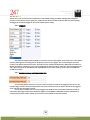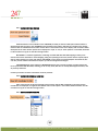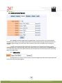
1
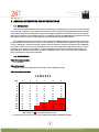
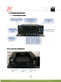
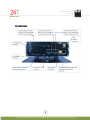
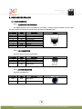
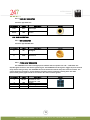
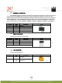
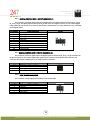
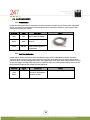
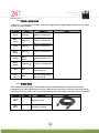
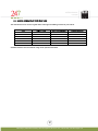
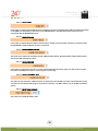
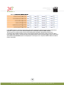
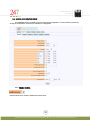
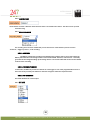
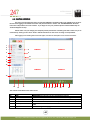
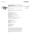
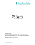
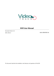
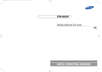
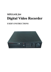
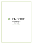
USERS MANUAL
mDVR306
Copyright © 2011, 247Security Inc. | 4400 North Point Parkway, Suite # 158, Alpharetta, GA 30022, USA | 1-866-693-7492 | www.247securityinc.com
USERS MANUAL
mDVR306
USER MANUAL
mDVR306
Rugged Digital Video Recorder
for In-Vehicle Applications
6 Video/Audio Channels
60fps Total
V11.0720
1
247Security Inc. | 4400 North Point Parkway, Suite # 158, Alpharetta, GA 30022, USA | 1-866-693-7492 | www.247securityinc.com
USERS MANUAL
mDVR306
TABLE of CONTENTS
1. GENERAL INFORMATION AND SPECIFICATIONS
1.1.
1.2.
1.3.
INTRODUCTION
SPECIFICATIONS
CONNECTORS & LED LOCATIONS
1.3.1. FRONT PANEL
1.3.2. BACK PANEL
2. PREPARATION FOR USE
2.1.
FRONT CONNECTORS
2.1.1. 10/100 BASE-T LAN CONNECTOR
2.1.2. USB 2.0 CONNECTOR
2.1.3. AUDIO OUT CONNECTOR
2.1.4. VIDEO OUT CONNECTOR
2.2.
BACK CONNECTORS
2.2.1. WIFI CONNECTOR
2.2.2. POWER INPUT CONNECTOR
2.2.3. CAMERA 1 – 6 CONNECTORS
2.2.4. USB 2.0 CONNECTOR
2.2.5. GPS CONNECTOR
2.2.6. GENERAL PURPOSE INPUT / OUTPUT CONNECTOR #1
2.2.7. GENERAL PURPOSE INPUT / OUTPUT CONNECTOR #2
2.2.8. EVENT MARKER CONNECTOR
2.3.
CABLE REQUIREMENTS
2.3.1. POWER CABLE
2.3.2. EVENT MARKER CABLE
2.3.3. SENSOR / ALARM CABLE
2.3.4. CAMERA CABLE
2.3.5. GPS MODULE CABLE
2.3.6. NETWORK CROSS-OVER CABLE
2.3.7. MINI USB CABLE
2.4.
CAMERA LENSES, WHAT VIEW, WHAT LENS
3. OPERATION
3.1.
STATUS INDICATORS
3.1.1. IGNITION LED
3.1.2. POWER LED
3.1.3. ERROR LED
3.1.4. VIDEO LOST LED
3.1.5. RECORD LED
3.2.
HDD ON/OFF LOCK
3.3.
MEDIA STORAGE REMOVAL
3.4.
WIRELESS VIDEO RETRIEVAL
3.5.
REMOTE POWER CONTROL
3.6.
EVENT MARKING AND RETRIEVAL
2
247Security Inc. | 4400 North Point Parkway, Suite # 158, Alpharetta, GA 30022, USA | 1-866-693-7492 | www.247securityinc.com
USERS MANUAL
mDVR306
4. CONNECTING TO DVR
4.1.
4.2.
4.3.
IP CONFIGURATION
CONNECT CROSS-OVER CABLE
SETTING UP YOUR PC
4.3.1. USING WINDOWS XP
4.3.2. USING WINDOWS VISTA
4.3.3. USING WINDOWS 7
5. DVR SETUP
5.1.
5.2.
5.3.
5.4.
5.5.
STARTING DVRVIEWER
DVRVIEWER LOGIN
CONNECTING TO DVR
SETUP LOGIN
SYSTEM CONFIGURATION MENU
5.5.1. DVR SERVER NAME
5.5.2. ADMIN PASSWORD
5.5.3. DVR TIME ZONE
5.5.4. SHUTDOWN DELAY (S)
5.5.5. STANDBY TIME (S)
5.5.6. MAXIMUM FILE SIZE (MB) & MAXIMUM FILE TIME (S)
5.5.7. VIDEO FRAME RATE
5.5.8. EVENT MARKER
5.5.9. PRE-LOCK TIME (S) & POST-LOCK TIME (S)
5.5.10. STOP RECORDING WHEN PLAY BACK
5.5.11. STOP RECORDING WHEN LIVE VIEW
5.5.12. ENABLE FILE ENCRYPTION
5.5.13. FILE ENCRYPTION PASSWORD
5.5.14. ENABLE GPS
5.5.15. ENABLE TAB102
5.5.16. ENABLE SMART UPLOAD
5.5.17. ENABLE BUZZER
5.5.18. ENABLE EXTERNAL WIFI
5.5.19. DRIVE-SAFE (G-FORCE SET-UP)
5.6.
CAMERA CONFIGURATION MENUS
5.6.1. ENABLE CAMERA
5.6.2. CAMERA NAME
5.6.3. RECORDING MODE
5.6.3.1. CONTINUE
5.6.3.2. TRIGGER BY SENSOR
5.6.3.3. NO RECORDING
5.6.4. BIT RATE
5.6.5. TRIGGERS
5.6.6. PRE-RECORDING & POST-RECORDING TIME
5.6.7. SHOW GPS SPEED ON OSD & SPEED DISPLAY
5.6.8. SHOW GPS COORDINATE ON OSD
5.6.9. RECORDING NOTIFICATION
5.7.
SENSOR CONFIGURATION MENU
5.7.1. SENSOR 1 TO 6
5.8.
NETWORK MENU
3
247Security Inc. | 4400 North Point Parkway, Suite # 158, Alpharetta, GA 30022, USA | 1-866-693-7492 | www.247securityinc.com
USERS MANUAL
mDVR306
5.9.
STATUS MENU
5.10. TOOLS MENU
5.10.1. DOWNLOAD CONFIGURATION
5.10.2. UPLOAD CONFIGURATION
5.10.3. UPDATE FIRMWARE & MCU FIRMWARE
6. DVRVIEWER
6.1.
6.2.
6.3.
6.4.
6.5.
6.6.
INTRODUCTION
SOFTWARE CLIENT FEATURES
SYSTEM REQUIREMENTS
INSTALLATION
STARTING DVRVIEWER
LIVE VIEW
6.6.1. SELECTING SCREEN LAYOUT
6.6.2. CAMERA SELECTION
6.6.3. CAMERA MENU
6.6.4. SNAPSHOT
6.6.5. SETUP
6.6.6. DISCONNECT
6.7.
PLAY ARCHIVE
6.7.1. SEARCH VIDEO BY CALENDAR AND TIMELINE BAR
6.7.2. SEARCH VIDEO BY EVENT
6.7.3. PLAY BACK CONTROL
6.7.4. EXPORT VIDEO
6.8.
PLAY FILE
6.9.
SNAPSHOT
6.10. USERS
6.10.1. USER MANAGEMENT
6.10.2. ADD/DELETE USER
6.10.3. CHANGE USER PASSWORD
6.11. ERASE STORAGE MEDIA
7. SUPPORT INFORMATION
8. LIMITED WARRANTY
4
247Security Inc. | 4400 North Point Parkway, Suite # 158, Alpharetta, GA 30022, USA | 1-866-693-7492 | www.247securityinc.com
USERS MANUAL
mDVR306
1. GENERAL INFORMATION AND SPECIFICATIONS
1.1. INTRODUCTION
DVR stands for Digital Video Recorder with one common goal, allowing end-users to record / retrieve real time
video files with a few mouse clicks. Within the last decade, video encrypt/decrypt algorithms achieved noticeable
improvement along with the availability of large capacity digital storage devices that draw attention to designing
DVR systems. With this in mind, 247Security Inc. has designed and built the mDVR306 Series equipment to make
this transition smooth for the in-vehicle applications, specifically the transportation industry.
The mDVR306 employs high performance video compression MPEG5 standard to optimize video/audio data
stream so that it can be sent over a network or stored directly on a local disk. The compression algorithm mainly
runs on a DSP Engine, therefore freeing up valuable resources within the system to do other jobs. The mDVR306
has features such as dynamic bit rate, controllable frame rate (max 60fps total), image quality control, real-time
previewing on all channels, alarm triggers, sensor configuration, easy retrieval and transfer of video files over
WIFI/LAN, GPS tracking and much more. In addition, mDVR306 allows end-users to independently manipulate
these parameters for each camera if desired.
1.2. SPECIFICATIONS
Video Recording Resolution
• D1 (720x480)
Video Compression
• MPEG5 compression, high quality video images and low bandwidth usage
Video Recording Frame Rate
CAMERAS
FPS
1
2
3
5
8
10
12
15
20
25
30
•
1
1
2
3
5
8
10
12
15
20
25
30
2
2
4
6
10
16
20
24
30
40
50
60
3
3
6
9
15
24
30
36
45
60
75
90
4
4
8
12
20
32
40
48
60
80
100
120
5
5
10
15
25
40
50
60
75
100
125
150
6
6
12
18
30
48
60
72
90
120
150
180
Note: options in RED are invalid and will not work
All channels can record simultaneously at 60fps total with D1 (720x480) resolution
5
247Security Inc. | 4400 North Point Parkway, Suite # 158, Alpharetta, GA 30022, USA | 1-866-693-7492 | www.247securityinc.com
USERS MANUAL
mDVR306
Video recording channels
• Up to 6 channels, 60fps total
Audio Recording Channels
• Up to 6 audio channels; Camera has built-in noise-reduction microphone
• One audio recording channel synchronized to each video recording channel
Camera connection
• Video, Audio, Power and Encryption all in one cable, with locking mechanism
Internal video storage
• Hot Swap Removable drive
• Up to 500 GB
• Rugged
• USB. 2.0
• Integrated heater
Wireless Network
• WLAN 802.11g
GPS
• GPS module can be connected to DVR using one cable, up to 40’ in length
• GPS data can be logged for over 15 years
Ethernet
• 10/100 Base-T Ethernet port
• IEEE 802.3u 100BASE-T Fast Ethernet compatible
Sensors
• Up to 8 sensors can be connected
Alarms
• Up to 4 alarms can be connected
Indicators
• Power LED (green)
• Ignition LED (green)
• Record LED (amber)
• Error LED (red)
• Video Lost LED (red)
PHYSICAL/POWER
Housing
Ionized Aluminum for rugged applications
6
247Security Inc. | 4400 North Point Parkway, Suite # 158, Alpharetta, GA 30022, USA | 1-866-693-7492 | www.247securityinc.com
USERS MANUAL
mDVR306
Form Factor
Depth: 184 mm (7.25 inches)
Width: 159 mm (6.25 inches)
Height: 51 mm (2 inches)
(Not including shock and vibration isolator)
Weight
Typically approximately 1.3 kg (2.8 lb)
(Not including shock and vibration isolator)
Power Supply
Vehicle power supply switcher
ESD protected
Battery
Lithium Coin Cell CR2032 (20.0 x 3.2 mm)
3 V / 235 mAh
Input Power Range
+8 VDC ~ +24 VDC normal operating voltage
+6 VDC ~ +28 VDC abnormal operating voltage up to 10 seconds
Over and under voltage protection
Ignition Signal / Power Down Timer
Software configurable delay power off signal from 1-120 minutes
50mA current draw in sleep mode after power down
Power Consumption
Typical 10W (5°C ~ 55°C)
DVR draws less than 24ma when off
ENVIRONMENT
Temperature Range
-30°C to +55°C (-22°F to +131°F) operating temperature
Relative Humidity
10% to 90% non-condensing
7
247Security Inc. | 4400 North Point Parkway, Suite # 158, Alpharetta, GA 30022, USA | 1-866-693-7492 | www.247securityinc.com
USERS MANUAL
mDVR306
1.3. CONNECTORS & LED LOCATIONS
1.3.1. FRONT PANEL w/ Door Closed
Front View w/Door Open & HDD Removed
8
247Security Inc. | 4400 North Point Parkway, Suite # 158, Alpharetta, GA 30022, USA | 1-866-693-7492 | www.247securityinc.com
USERS MANUAL
mDVR306
1.3.2 BACK PANEL
9
247Security Inc. | 4400 North Point Parkway, Suite # 158, Alpharetta, GA 30022, USA | 1-866-693-7492 | www.247securityinc.com
USERS MANUAL
mDVR306
2. PREPARATION FOR USE
2.1. FRONT CONNECTORS
2.1.1. 10/100BASE-T LAN CONNECTOR
The RJ45 port allows access to the DVR from your laptop / computer using the included cross over cable.
This port is labeled as LAN and has a default static IP address of 192.168.1.100.
Pin Number
1
2
3
4
5
6
7
8
9
Signal
TX+
TXRX+
RXNC
COM
COM
COM
COM
Description
Pin out
Transmit Data +
Transmit Data Receive Data +
Receive Data Not connected
Common
Common
Common
Common
2.1.2. USB 2.0 CONNECTOR
Connector type: 4-pin friction-lock header
Pin Number
Signal
4
GND
1
2
3
VCC
-Data
+Data
Description
Pin out
Cable Power +5 V
Balanced Data Line Balanced Data Line +
Cable Ground
2.1.3. AUDIO OUT CONNECTOR
Connector type: RCA Jack
Pin Number
Signal
Description
Inside
Audio
Audio Signal
Outside
GND
Ground
Pin out
10
247Security Inc. | 4400 North Point Parkway, Suite # 158, Alpharetta, GA 30022, USA | 1-866-693-7492 | www.247securityinc.com
USERS MANUAL
mDVR306
2.1.4. VIDEO OUT CONNECTOR
Connector type: RCA Jack
Pin Number
Signal
Description
Inside
Video
Video Signal
Outside
GND
Ground
Pin out
2.2. BACK CONNECTORS
2.2.1. WIFI CONNECTOR
Connector type: RP-SMA Jack
Pin Number
Signal
Description
1
RF
RF Signal
2
GND
RF Ground
Pin out
2.2.2. POWER INPUT CONNECTOR
The mDVR306 has a built-in Intelligent power switcher that can operate from +8V ~ +24V DC-IN. The
ON/OFF signal connects to the vehicle’s ignition signal. The mDVR306 uses this signal to trigger the power shut-off
delay and the timing circuitry. The mDVR306 will remain ON until the shut-off delay time has been reached. The
system will then go through its normal shutdown procedures before completely powering down. The GND
(Common DC ground) signal should be connected to the vehicle common ground.
Pin Number
Signal
1
ON/OFF
2
3
4
GND
VIN
GND
Description
On/Off Switch
On when 6V ~ VIN
Off when 0V ~ 0.5V
Ground
Input voltage (+8V~+24VDC)
Ground
Pin out
11
247Security Inc. | 4400 North Point Parkway, Suite # 158, Alpharetta, GA 30022, USA | 1-866-693-7492 | www.247securityinc.com
USERS MANUAL
mDVR306
2.2.3. CAMERA 1-6 CONNECTORS
The mDVR306 supports a maximum of 6 cameras. These Micro-fit connectors are used to connect the six
camera inputs to the mDVR306 system (video and audio) using a gang plug adapter for cameras 1-4. Also
included in each camera connection is DV12V Out to power the camera. You can refer to the cover of the DVR for
the PIN assignments of each connector. If any of these cameras are not connected properly (for instance loose
cables, unplugged etc…) than the mDVR306 intelligently notifies the end-users with “NO VIDEO” on the preview
screen. Camera inputs are labeled CAMERA 1, CAMERA 2, CAMERA 3, CAMERA 4, CAMERA 5, and CAMERA 6
Pin Number
1
2
3
4
5
6
Signal
MIC-IN
GND
Video+
Video+12VDC
GND
Description
Microphone In
Ground
Video In (+)
Video In (-)
+12VDC OUT
Ground
Pin out
2.2.4. USB 2.0 CONNECTOR
Connector type: 4-pin friction-lock header
Pin Number
1
2
3
4
Signal
VCC
-Data
+Data
GND
Description
Cable Power +5 V
Balanced Data Line Balanced Data Line +
Cable Ground
Pin out
2.2.5. GPS CONNECTOR
Connector type: RP-SMA Jack
Pin Number
Signal
Description
1
RF
RF Signal
2
GND
RF Ground
Pin out
12
247Security Inc. | 4400 North Point Parkway, Suite # 158, Alpharetta, GA 30022, USA | 1-866-693-7492 | www.247securityinc.com
USERS MANUAL
mDVR306
2.2.6. GENERAL PURPOSE INPUT / OUTPUT CONNECTOR #1
This connector provides 5 digital inputs and 1 digital output. The digital inputs are labeled as DI_1, DI_2,
DI_3, DI_4, DI_5. The digital output is labeled as DO_3. End-users can assign any sensors to one of these digital
input signals. Up to 5 sensors can be wired to this connector. Alternatively, one alarm (LED, Siren, etc.) is available
on the digital output.
Pin Number
1
2
3
4
5
6
7
8
9
10
Signal Description
Input DI_1
Input DI_2
Input DI_3
Input DI_4
Input DI_5
Output DO_3
GND
GND
+10V Standby
+10V Standby
Pin out
2.2.7. GENERAL PURPOSE INPUT / OUTPUT CONNECTOR #2
This connector provides 3 digital inputs. The digital inputs are labeled as DI_6, DI_7, DI_8. End-users can
assign any sensors to one of these digital input signals, up to 3 sensors can be wired to this connector. This
connector also provides +12VDC OUT on pin 4 with a built-in 0.75A fuse.
Pin Number
1
2
3
4
Input DI_6
Input DI_7
Input DI_8
Signal Description
Pin out
2
+12VDC OUT
1
2.2.8. EVENT MARKER CONNECTOR
This connector is used to plug in the included event marker cable.
Pin Number
1
2
3
4
5
6
DI_0
GND
+12V OUT
Output DO_0
Output DO_1
Output DO_2
Signal Description
Pin out
13
247Security Inc. | 4400 North Point Parkway, Suite # 158, Alpharetta, GA 30022, USA | 1-866-693-7492 | www.247securityinc.com
USERS MANUAL
mDVR306
2.3. CABLE REQUIREMENTS
2.3.1. POWER CABLE
A 15 ft three wire power cable is included for connection between the DVR and your vehicle power and ignition
signals. It is highly recommended that in-line fast blow fuses (7.5 amps) be installed on the two power input
connections for safety pre-cautions.
Wire Color
Signal
Description
Picture
Red
VIN
Input voltage (8~24VDC)
Black
GND
Ground
White
ON/OFF
Ignition switched power
(only hot when ignition is
in RUN/ACC
2.3.2. EVENT MARKER CABLE
A 15 ft cable is already connected to the Event Marker and pre-wired to a 2X3 Molex connector; the Molex
connector will then connect to the event marker port on the back of the DVR. The event marker uses 3 digital
outputs for Video Lost, Recording & Power LED’s and 1 digital input for the push button. The push button is used
for pre/post trigger recording which when pressed, marks the video files at that specific moment. Pre-event and
Post-event time locking can be configured in the DVR setup.
Connector
6-Pin
Molex
Signal
Description
Picture
Connects to Event Marker
connector on DVR
14
247Security Inc. | 4400 North Point Parkway, Suite # 158, Alpharetta, GA 30022, USA | 1-866-693-7492 | www.247securityinc.com
USERS MANUAL
mDVR306
2.3.3. SENSOR / ALARM CABLE
A 15 ft sensor / alarm cable is provided to connect the 4 digital inputs, 1 digital output and motion sensor signals
to the GP I/O port of the DVR.
Wire Color
Signal
Brown
Input DI_1
White/
Green
Input DI_2
Green
Input DI_3
White/
Orange
Input DI_4
Orange
Motion
Sensor
White/
Brown
Output DO_3
Description
Connects to Digital Input 1
of GP I/O connector (Pin
1)
Connects to Digital Input 2
of GP I/O connector (Pin
2)
Connects to Digital Input 3
of GP I/O connector (Pin
3)
Connects to Digital Input 4
of GP I/O connector (Pin
4)
Connects to Motion Sensor
of GP I/O connector (Pin
5)
Connects to Digital Output
3 of GP I/O connector (Pin
6)
Blue
GND
Connects to GND of GP I/O
connector (Pin 7)
White/
Blue
GND
Connects to GND of GP I/O
connector (Pin 8)
Picture
2.3.4. CAMERA CABLE
STP (shielded twisted pair) cable is the standard and will use 2X3 Molex plugs for connections making the
installation simple and straight forward. The cable connectors are keyed so they cannot be connected incorrectly.
Connect one end of the cable to one of the available camera inputs on the DVR and the other end into the camera.
Connector
Signal
Description
6-Pin
Molex
Connects to DVR
6-Pin
Molex
Connects to camera
Picture
15
247Security Inc. | 4400 North Point Parkway, Suite # 158, Alpharetta, GA 30022, USA | 1-866-693-7492 | www.247securityinc.com
USERS MANUAL
mDVR306
2.3.5. GPS MODULE CABLE
A GPS module attached to a 25 ft cable connects to the back of the DVR using an RP-SMA connector
Connector
Signal
Description
Picture
Connects to GPS
connector on DVR
RP-SMA Jack
2.3.6. NETWORK CROSS-OVER CABLE
This cable connects a computer / laptop to the 10/100BASE-T LAN connector using the network standard RJ45
connector so that user can setup the DVR parameters as well as preview the video and audio from the video
channels.
Connector
Signal
Description
Picture
Connects to 10/100BASET LAN connector
RJ45
2.3.7. MINI USB CABLE
This cable connects the mDVR removable storage media to your computer or laptop for video / audio playback.
This is a standard USB 2.0 Type A to 5 Pin mini-B Cable which should be no longer than 12 to 16 inches. See
section 6 for instructions on how to use the DVRViewer application to connect to the storage media and play back
your recorded video and audio.
Connector
Signal
Description
USB 2.0 Type
A
Connects to your
computer
USB 2.0
5 Pin mini-B
Connects to the mDVR
storage media
Picture
16
247Security Inc. | 4400 North Point Parkway, Suite # 158, Alpharetta, GA 30022, USA | 1-866-693-7492 | www.247securityinc.com
USERS MANUAL
mDVR306
2.4. CAMERA LENSES, WHAT VIEW, WHAT LENS
The chart below can be used as a guide when ordering and installing cameras in your vehicle.
Lens
2.9mm
3.6mm
6.0mm
8.0mm
12mm
16mm
Angle of View
120°
92°
54°
39°
26°
19°
Best focus distance
4 ft
5 ft
8 ft
10 ft
13 ft
20 ft
Viewable distance
10 ft
12 ft
20 ft
28 ft
35 ft
56 ft
Viewable distance means maximum range of the optimum standard
17
247Security Inc. | 4400 North Point Parkway, Suite # 158, Alpharetta, GA 30022, USA | 1-866-693-7492 | www.247securityinc.com
USERS MANUAL
mDVR306
3. OPERATION
3.1. STATUS INDICATORS
3.1.1. IGNITION LED
This LED is to notify the operator that the vehicle’s ignition has been turned on which will then turn on the DVR.
This LED will be blinking when ignition is turned on and until DVR powers on. This LED will also blink when ignition
is turned off and until DVR powers off.
3.1.2. POWER LED
This LED is to notify operator that system power is on.
3.1.3. ERROR LED
This LED is to notify operator that the system has encountered a problem and cannot continue normal operation.
Please call tech support for troubleshooting procedures.
3.1.4. VIDEO LOST INDICATOR LED
This LED is to notify operator when any of the enabled cameras loses video signal meaning the cable is cut, not
connected or the camera is having a problem.
3.1.5.RECORD LED
This LED indicates if the DVR is recording.
3.2. HDD ON/OFF LOCK
The HDD On/Off lock mechanism is employed to prevent unauthorized operators from removing the media
storage and tampering with video data. Turn key to position “Close” to lock media storage or “Open” to unlock. The
mDVR306 will NOT record video if the lock mechanism is in the “Open” position
3.3. MEDIA STORAGE REMOVAL
The media storage is hot swappable and can be removed and inserted without turning the ignition off. This process
will take roughly 10 to 20 seconds to complete. The feature is helpful when access to video is needed but vehicle
is still running its’ route. User can remove the media storage and insert a new one so that the needed video can be
retrieved right away.
1. Turn key to the “Open” position
This process is necessary so that the mDVR306 can properly close all video/audio files and safely turn
HDD
power off. Remove the front cover plate.
2. Gently pull media storage out from the bay
3. Insert new media storage – Wait for at least 30 seconds (Power LED is OFF) then insert new/original
storage media, re-install the cover.
18
247Security Inc. | 4400 North Point Parkway, Suite # 158, Alpharetta, GA 30022, USA | 1-866-693-7492 | www.247securityinc.com
USERS MANUAL
mDVR306
4. Turn key to the “Close” position
The mDVR306 will now turn the HDD power on, detect the new media and start recording again.
3.4. WIRELESS VIDEO RETRIEVAL
(Refer to SmartServer manual)
3.5. REMOTE POWER CONTROL
(Future implementation)
3.6. EVENT MARKING AND RETRIEVAL
(Refer to Event Marking/USB Retrieval guide)
19
247Security Inc. | 4400 North Point Parkway, Suite # 158, Alpharetta, GA 30022, USA | 1-866-693-7492 | www.247securityinc.com
USERS MANUAL
mDVR306
4. CONNECTING TO DVR
4.1. IP CONFIGURATION
The DVR default IP address is 192.168.1.100. The DVR is set up with a STATIC IP address to allow for a direct
connection with a cross-over cable. During installation the DVR can be connected to a laptop allowing the installer
to preview the cameras for aiming purposes.
4.2. CONNECT CROSS-OVER CABLE
During installation the DVR can be connected to a laptop allowing the installer to preview the cameras for aiming
purposes. Using the grey cross-over cable shipped with the DVR, attach one end to the DVR port labeled LAN and
the other end to the LAN port on the laptop. To verify the correct cable is used check the end of the cable for the
“XOVER” label. Note: A patch cable (standard network cable) will not work.
4.3. SETTING UP YOUR PC
4.3.1. USING WINDOWS XP
4.3.1.1.
4.3.1.2.
4.3.1.3.
4.3.1.4.
4.3.1.5.
4.3.1.6.
4.3.1.7.
4.3.1.8.
4.3.1.9.
4.3.1.10.
4.3.1.11.
4.3.1.12.
Right click on My Network Places
Go to Properties and left click
Right click on Local Area Connection
Go to Properties and left click
Left click on Internet Protocol (TCP/IP)
Left click on Properties
Record ANY numbers on this screen for your record if needed
Left click on Use the following IP Address button
In the IP address window type 192.168.1.55
Left click mouse on Subnet mask and you should have 255.255.255.0
There should be no other numbers in the TCP/IP properties
Left click on OK or Close
4.3.2. USING WINDOWS VISTA
4.3.2.1.
4.3.2.2.
4.3.2.3.
4.3.2.4.
4.3.2.5.
4.3.2.6.
4.3.2.7.
4.3.2.8.
4.3.2.9.
4.3.2.10.
4.3.2.11.
4.3.2.12.
4.3.2.13.
4.3.2.14.
Right click on the Network icon on the desktop
Go to Properties and left click
Find Manage network connections under Tasks and left click
Right click on Local Area Connection
Go to Properties and left click
Message appears asking permission to continue, left click to continue
Left click on Internet Protocol Version 4 (TCP/IPv4)
Then left click on Properties
Record ANY numbers on this screen for your records if needed
Left click on Use the following IP Address button
In the IP address window type 192.168.1.55
Left click on Subnet mask and you should have 255.255.255.0
There should be no other numbers in the TCP/IP properties
Left click on OK or Close
Note: If the steps in setting up your PC do not work, contact you IT department concerning your PC, this is a one-time setup.
20
247Security Inc. | 4400 North Point Parkway, Suite # 158, Alpharetta, GA 30022, USA | 1-866-693-7492 | www.247securityinc.com
USERS MANUAL
mDVR306
4.3.3. USING WINDOWS 7
4.3.3.1.
Click on the Start button in the lower left corner
4.3.3.2.
Select control panel
4.3.3.3.
Select and open Network and Sharing center
4.3.3.4.
Select Change adapter settings
4.3.3.5.
Right click on Local Area Connection
4.3.3.6.
Go to properties and left click
4.3.3.7.
Left click on Internet Protocol Version 4 (TCP/IPv4)
4.3.3.8.
Left click on Properties
4.3.3.9.
Record ANY numbers on this screen for your records if needed
4.3.3.10.
Left click on Use the following IP Address button
4.3.3.11.
In the IP address window type 192.168.1.55
4.3.3.12.
Left click on Subnet mask and you should have 255.255.255.0
4.3.3.13.
There should be no other numbers in the TCP/IP properties
4.3.3.14.
Left click on OK
4.3.3.15.
Left click on Close
Note: If the steps in setting up your PC do not work, contact you IT department concerning your PC, this is a one-time setup.
21
247Security Inc. | 4400 North Point Parkway, Suite # 158, Alpharetta, GA 30022, USA | 1-866-693-7492 | www.247securityinc.com
USERS MANUAL
mDVR306
5. DVR SETUP
5.1. STARTING DVRVIEWER
Verify that the mDVR306 has successfully powered up by checking the Power and Ignition LEDs which should be
on and solid. The HDD Power LED should also be on. You can start the viewer software by finding the DVRViewer
folder listed in the program folder in the start menu. Double-clicking on the icon “DVRViewer”. The DVRViewer
software should be included on the installation CD that is sent along with the unit. The mDVR306 requires
DVRViewer version 11.0418 or higher (April 18, 2011)
5.2. DVRVIEWER LOGIN
The first screen that appears when you start the DVRViewer application will be the LOGIN screen. If this is the first
time logging in the default username and password will be “admin” and “247SECURITYINC”. Both the Username
and password are case sensitive. If you forget or lose your password please contact 247Security Inc. Technical
Support for help.
Please make sure you change your temporary admin password to something else that is easier for you to
remember by clicking on the “Users” button. Follow instructions on the screen to assign a new password.
22
247Security Inc. | 4400 North Point Parkway, Suite # 158, Alpharetta, GA 30022, USA | 1-866-693-7492 | www.247securityinc.com
USERS MANUAL
mDVR306
5.3. CONNECTING TO DVR
Once the DVRViewer application is running click on the play button and selects “Live View”. You will get the
following window:
Select the DVR you want to connect to so that it’s highlighted and then click on “Connect” button. The first time
you do this the default bus ID of bus001 – 192.168.1.100 will appear in the window.
5.4. SETUP LOGIN
In this section, we will discuss how to configure the mDVR306 to meet your requirements. The process is
straightforward and easy to follow; the DVR setup is divided into six major components: SYSTEM, CAMERA,
SENSOR, NETWORK, STATUS and TOOLS. The system will already have been configured at the factory for your
specific system requirements, but of course can be updated as needed.
You can access the SYSTEM CONFIGURATION by clicking on the “SETUP” button from the DVRViewer application
and login in using the default username and password of “admin” and “admin”.
23
247Security Inc. | 4400 North Point Parkway, Suite # 158, Alpharetta, GA 30022, USA | 1-866-693-7492 | www.247securityinc.com
USERS MANUAL
mDVR306
5.5. SYSTEM CONFIGURATION MENU
The system configuration menu is where you configure general parameters such as the name of the DVR, time
zone, shutdown delay, etc. Also the G-Force set-up parameters are here if the Drive-Safe module is attached to the
DVR.
24
247Security Inc. | 4400 North Point Parkway, Suite # 158, Alpharetta, GA 30022, USA | 1-866-693-7492 | www.247securityinc.com
USERS MANUAL
mDVR306
5.5.1. DVR SERVER NAME
DVR Server Name allows end-user to individually assign each mDVR306 installed in the field a unique name so
that the client software can easily communicate with each individual DVR system. DVRViewer can communicate
and configure multiple mDVR306 systems simply by scanning all mDVR306 servers on the network. DVRViewer
then composes a list of all available mDVR306 systems that the end-user can select to gain access to such
systems. This feature is illustrated by clicking on “Play” and selecting “Live View”; you will see a list of all
mDVR306 servers that you can select. By Clicking on any selected DVR server name you gain access to that
particular mDVR306 system. The additional data to possibly input is the bus number as part of the text overlay.
Highlight the “BUS001” in the server name box and change the bus name using letters & numbers with a
maximum of 16 characters.
Note: (DO NOT USE Spaces or symbols)
5.5.2. ADMIN PASSWORD
This is the DVR setup admin password which can be changed to avoid unauthorized access. Make sure the
new password is recorded somewhere. The DVR setup login user name is “admin” and cannot change.
5.5.3. DVR TIME ZONE
The time zone set here will be the time zone where the vehicle will be operated.
25
247Security Inc. | 4400 North Point Parkway, Suite # 158, Alpharetta, GA 30022, USA | 1-866-693-7492 | www.247securityinc.com
USERS MANUAL
mDVR306
5.5.4. SHUTDOWN DELAY (S)
The Shutdown Delay parameter is used to control how long you want to keep the mDVR306 recording after the
ignition key is switched to the OFF position in the vehicle. For instance, once the ignition key is switched OFF, the
system will delay another x seconds (x seconds is the number that you have entered in the box from 10 seconds to
1200 seconds (20 minutes)) before shutting off mDVR306 system’s power completely. This technique prevents
potential file corruption or system crash the next time it boots up. The default value of 120 seconds is pre-set in
the DVR.
5.5.5. STANDBY TIME (S)
The Standby mode will enable the DVR to enter into a low power consumption state so that after the
vehicle’s ignition has been turned off, DVR can still be accessed via the Wi-Fi connection for DVR configuration, live
view and play back of video. When DVR enters standby mode, many hardware components are shut down to
conserve power, recording of video is disabled and SmartServer upload occurs.
5.5.6. MAXIMUM FILE SIZE (MB) & MAXIMUM FILE TIME (S)
The menu basically defines how video files are recorded on the removable hard drive(s). There are two
modes that video files can be recorded. (1) Video files can be recorded by file size “Maximum File (MB)” or (2) by
file length “Maximum File Time (s)”. In the field “Maximum File Size (MB)”, you can enter values ranging from 10
MB to 300 MB. In the field “Maximum File Time (s)”, you can enter values ranging from 60 seconds to 7200
seconds (2 hours).
There are pros and cons associated to each value you enter into this box. It can either slow down or speed
up specific features of the DVR, for example, searching files in Play Back Mode, uploading video in the
SmartServer upload process.
It is recommended the “Maximum File (MB)” values be from 100MB to 300MB for optimal performance.
Each individual video file is broken into or stops recording when it has exceeded these programmable values and a
new video file is automatically generated to continue the recording process.
26
247Security Inc. | 4400 North Point Parkway, Suite # 158, Alpharetta, GA 30022, USA | 1-866-693-7492 | www.247securityinc.com
USERS MANUAL
mDVR306
5.5.7. VIDEO FRAME RATE
The frame rate listed is per camera (fps). NOTE: selecting a combination of number of cameras and FPS that
exceeds the 60FPS total of the system will cause the system to experience issues. (example: 4 Cameras X 15fps =
60fps total which will work, BUT 5 Cameras X 15fps = 75fps which will not work)
5.5.8. EVENT MARKER
This drop down list will enable you to select which sensor to use for the event marker. The Event Marker
(Sensor 1) is the default sensor to be used with the included event marker cable unless there is a required custom
solution to use a different sensor.
5.5.9. PRE-LOCK TIME (S) & POST-LOCK TIME (S)
Pre-Lock Time (in seconds) defines how many seconds you want to include in the marked video event file
prior to the time that special event occurs. For instance, if the Event Marker Button was pressed at 12:00pm and
the Pre-Lock value was 60 then the marked video event file is generated to start at 11:59am exactly or a minute
prior to the “event time”.
Similarly, Post-Lock Time is the time that occurs after the “event time”. For instance a value of 60 entered
in Post-Lock will mark the file to stop at 12:01pm. Therefore, you have a marked video file that starts from
27
247Security Inc. | 4400 North Point Parkway, Suite # 158, Alpharetta, GA 30022, USA | 1-866-693-7492 | www.247securityinc.com
USERS MANUAL
mDVR306
11:59am until 12:01pm. The mDVR306 allows the end-user to set the Pre-Lock and Post-Lock up to 600 seconds
(10 Minutes). Values entered into these boxes are in seconds.
5.5.10. STOP RECORDING WHEN PLAY BACK
This option will disable recording when the DVRViewer application is connected to the mDVR in play back mode.
Click this check box to enable this feature which will improve simultaneous multiple video channel play back.
5.5.11. STOP RECORDING WHEN LIVE VIEW
This option will disable recording when the DVRViewer application is connected to the mDVR in live view mode.
Click this check box to enable this feature which will improve simultaneous multiple video channel live view.
5.5.12. ENABLE FILE ENCRYPTION
If this option is enabled, a password is required to encrypt the video / audio files. When playing back these same
video / audio files the password will be requested. This is an additional security feature to keep unauthorized users
from viewing the video. Note: (If the password is lost, the video CAN NOT be retrieve)
5.5.13. FILE ENCRYPTION PASSWORD
If file encryption is enabled (see above), this is where the password is set.
Warning: If you enable file encryption and forget your password, you will NOT be able to play back your recorded
video / audio files.
28
247Security Inc. | 4400 North Point Parkway, Suite # 158, Alpharetta, GA 30022, USA | 1-866-693-7492 | www.247securityinc.com
USERS MANUAL
mDVR306
5.5.14. ENABLE GPS
If this option is enabled and the GPS antenna is installed you will be collecting all the GPS information and storing
on the HDD to be uploaded at a later time via the USB GPS Stick or the WIFI Touchdown system process in
conjunction with the MiniTRACK process.
5.5.15. ENABLE TAB102
If this option is enabled the Drive-Safe™ external G-Force module for G-Force data collection in conjunction with
the MiniTRACK or WIFI Touchdown system is connected
5.5.16. ENABLE SMART UPLOAD
This needs to be enabled for automatic upload of Marked Video Events, Requested Video, GPS and Drive-Safe™
data via the WIFI Touchdown system.
5.5.17. ENABLE BUZZER
If this option is enabled and you have an event marker button with the buzzer option, you will receive an audio
tone when the DVR powers up and a camera signal is not working.
5.5.18. ENABLE EXTERNAL WIFI
This option is only enabled for a DVR that does not include the internal WIFI connection. This would allow for the
connection of the external WIFI bridge to work with an otherwise “non-WIFI” DVR for use on the WIFI Touchdown
system.
5.5.19. INPUT VIDEO FORMAT
This can be set at NTSC (default) or PAL.
29
247Security Inc. | 4400 North Point Parkway, Suite # 158, Alpharetta, GA 30022, USA | 1-866-693-7492 | www.247securityinc.com
USERS MANUAL
mDVR306
5.5.20. DRIVE-SAFE (G-FORCE SET-UP)
If the TAB102 option is checked as listed above, the G-Force parameters will then appear on the system set-up
page after a system re-boot. NOTE: DO NOT CHANGE ANY OF THE BASE, PEAK OR CRASH VALUES.
The only values to possibly change are those associated with the UPLOAD. The Upload process works in
conjunction with the WIFI Touchdown system, systematically uploading 30 seconds of video pre & post if the GForce trigger point meets or exceeds the value in the Upload column for the associated trigger. G-Force data values
work with the GPS MiniTRACK option to be displayed in a text report or on a map. See the Drive-Safe™ manual for
further clarification.
30
247Security Inc. | 4400 North Point Parkway, Suite # 158, Alpharetta, GA 30022, USA | 1-866-693-7492 | www.247securityinc.com
USERS MANUAL
mDVR306
5.6. CAMERA CONFIGURATION MENUS
The mDVR306 series is available in the 6 camera inputs configuration. You can select any camera by
clicking on its tab where a sub-menu is available for configuration.
5.6.1. ENABLE CAMERA
Click the check box to enable or disable the camera input.
31
247Security Inc. | 4400 North Point Parkway, Suite # 158, Alpharetta, GA 30022, USA | 1-866-693-7492 | www.247securityinc.com
USERS MANUAL
mDVR306
5.6.2. CAMERA NAME
Each camera can have a different name based on where it is located in the vehicle. The value can be up to 16
characters long.
5.6.3. RECORDING MODE
For recording, there are three modes that you can select from. Each camera input can record in
“Continue”, “Trigger by sensor”, or No recording.
5.6.3.1. CONTINUE
The DVR is continuously recording in the background no matter what. It never stops unless the
DVR is powered down or the storage media is removed from DVR. Therefore, video files are constantly
generated in the background filling up the storage device. It is recommended this mode to be the default
mode for video recording.
5.6.3.2. TRIGGER BY SENSOR
In this mode, the DVR only records if it detects an event trigger on one of the programmable sensors. If
this is the mode you want your DVR to use then don’t forget to enable the required sensors.
5.6.3.3. NO RECORDING
This mode disables the camera input.
5.6.4. BIT RATE
32
247Security Inc. | 4400 North Point Parkway, Suite # 158, Alpharetta, GA 30022, USA | 1-866-693-7492 | www.247securityinc.com
USERS MANUAL
mDVR306
The bit rate is also pre-set from the manufacturer to the default setting of 1 Mbps. Changing this setting will
increase or decrease the picture quality, the smaller the bit rate the smaller the file size but less picture quality;
the bigger the bit rate the bigger the file size and better picture quality.
5.6.5. TRIGGERS
The DVR has 8 digital inputs available to connect to sensors. This triggers menu allows you to select which
sensor(s) will trigger the recording process. By placing a check in the “Trigger” box corresponding to the sensor
number on its left will activate that sensor. All sensors can be enabled simultaneously. OSD stands for On-ScreenDisplay; this feature embeds the sensor name (assignable by end-user) into the video files. When playing back the
video, the sensor(s) can be identified by the embedded text on the video. Placing a check mark on the OSD box
enables this feature.
5.6.6. PRE-RECORDING & POST-RECORDING TIME
Pre-recording defines how many seconds of video you want to include in the triggered event prior to the
time the trigger occurred. Post-recording defines how many seconds of video you want to include in the triggered
event after the time the trigger occurred.
For the above example, if the sensor got triggered at 12:00:00, the event would include 30 seconds of
video before the trigger and 30 seconds after the trigger, from 11:59:30 to 12:00:30 creating a marked event
containing 60 seconds of video. Values can be from 1 second to 600 seconds (10 minutes).
33
247Security Inc. | 4400 North Point Parkway, Suite # 158, Alpharetta, GA 30022, USA | 1-866-693-7492 | www.247securityinc.com
USERS MANUAL
mDVR306
5.6.7. SHOW GPS SPEED ON OSD
GPS information is also available on the mDVR306 provided you have the GPS option which includes a
GPS antenna that connects to the mDVR306 and is installed on the vehicle. GPS data is recorded on the storage
media as well as embedded into the video stream. Place a check mark in the box to display and record the vehicle
GPS speed in the video stream. Speed can be displayed in “mph” or “km/h”. If this option is not enabled, GPS data
is still recorded in a log file on the video storage media.
MiniTRACK is a software application, combining recorded GPS data with GIS mapping to allow you to
monitor vital vehicle information. Track Stopping, Idling and speeding occurrences; Create custom reports; Export
data to other software for review and analysis. MiniTRACK not only helps reconstruct disputes and incidents, but
can also provide valuable information to improve your fleet management strategies.
VideoTRACK builds on the features of MiniTRACK allowing you to visually manage recorded video that’s
been synchronized with GPS data, enabling you to not only know, but also see exactly what happened where, and
at precisely what time.
Contact your dealer for further information on these products.
5.6.8. SHOW GPS COORDINATE ON OSD
Place a check mark in this box to display and record the vehicle GPS coordinates in the video stream.
Coordinates are displayed as longitude and latitude values. If this option is not enabled, GPS coordinates are still
recorded in a log file on the video storage media
5.6.9. RECORDING NOTIFICATION
34
247Security Inc. | 4400 North Point Parkway, Suite # 158, Alpharetta, GA 30022, USA | 1-866-693-7492 | www.247securityinc.com
USERS MANUAL
mDVR306
5.7. SENSOR CONFIGURATION MENU
The mDVR306 provides 8 digital inputs. The digital inputs are used to connect to any sensors that are
available in your vehicle. You can assign a unique name to all sensors listed in the menu. Shown in the menu are
the factory default settings. The sensor name will be recorded on your video file if OSD (On-Screen-Display) is
enabled.
“Inverted” defines how the sensor should work. For instance, if you check the box “Inverted” then the
mDVR306 detects “0” as the active state of the sensor. If the check box is un-checked then the mDVR306 detects
“1” as the active state of the sensor. Please make sure you understand how your sensors work before connecting
them to the digital inputs.
5.7.1. SENSOR 1 TO 6
This optional lets you enter the sensor name for the specified digital input and select what the active state
of the sensor should be when triggered.
35
247Security Inc. | 4400 North Point Parkway, Suite # 158, Alpharetta, GA 30022, USA | 1-866-693-7492 | www.247securityinc.com
USERS MANUAL
mDVR306
5.8. NETWORK MENU
The default Ethernet IP address of the mDVR306 is “192.168.1.100” and should not be modified unless
necessary. If this IP address is modified the user will NOT be able to access the DVR if the IP address is lost.
The default wireless IP address of the mDVR306 is “192.168.3.100” and can be changed to integrate the
unit into your wireless infrastructure. The wireless Essid and encryption key can be obtained from your IT
department and entered into this page. Once setup is complete, the DVR can be accessed via your wireless
network. If the SmartServer option is purchased, the DVR can automatically upload video events upon wireless
range of your access point. For example, if your vehicles are all equipped with the wireless option and you have
purchased the SmartServer technology, your vehicles upon returning from their route will automatically upload to
your SmartServer computer all the video events. User can then review the video events from within the office or
from a remote location with access to the SmartServer computer.
The default gateway IP address is used when DVR needs to accessed remotely via the Internet or from a
different network. The default gateway IP address is usually your router IP address. Contact your dealer for further
information.
36
247Security Inc. | 4400 North Point Parkway, Suite # 158, Alpharetta, GA 30022, USA | 1-866-693-7492 | www.247securityinc.com
USERS MANUAL
mDVR306
5.9. STATUS MENU
This tab displays the current system configuration and a real time heath status summary of the DVR.
Starting from the top, this tab informs the user which firmware versions are currently loaded, number of cameras,
sensors and alarms the DVR currently supports and the current DVR time as well as your local computer time.
The local computer time is extracted from your computer which is currently connected to the DVR.
The “Synchronize DVR Time” button will synchronize the DVR time with the local time on the connected
laptop or computer.
The information below the “Synchronize DVR Time” button provides the user a general system health of
the DVR as well as indication of all camera inputs status.
37
247Security Inc. | 4400 North Point Parkway, Suite # 158, Alpharetta, GA 30022, USA | 1-866-693-7492 | www.247securityinc.com
USERS MANUAL
mDVR306
5.10.
TOOLS MENU
This tab will allow the user to backup the DVR configuration as well as update the firmware. There may
be future releases of the DVR firmware that may contain new features or improvements. Contact your dealer for
firmware updates.
5.10.1. DOWNLOAD CONFIGURATION
This option is useful and will save you time when multiple mDVR306 systems need to be configured.
Once the DVR has been configured, click the “Download” button to save your settings to a file on your desktop or a
location of your choice.
Click the “Download” button and the following window will appear
38
247Security Inc. | 4400 North Point Parkway, Suite # 158, Alpharetta, GA 30022, USA | 1-866-693-7492 | www.247securityinc.com
USERS MANUAL
mDVR306
Select a folder location of your choice and click the “Save” button. A file named “mvdr.cfg” will be saved
the chosen location. You can then rename this file to whatever you want to better identify which DVR it came from.
For example, you can rename the file to incorporate the vehicle name and the date it was configured like the
following: “BUS109-310709.cfg”.
5.10.2. UPLOAD CONFIGURATION
This option allows you to select a backup configuration file and upload it to the DVR. This feature will
overwrite all the current settings with the settings from the configuration file. The only value you may need to
change is the “DVR Server name” under the System tab because it was just overwritten with “DVR Server name”
from the configuration file. Note: All previous video data on the DVR will be lost if you do an upload.
Note: Download and Upload Configuration feature is not compatible between different versions of firmware; this
feature should only be used when deploying multiple DVRs with same hardware and software. Installer would
configure the first DVR and then download the configuration to his computer, when installing the subsequent
DVRs, installer merely has to upload the previously save configuration and change the DVR name.
39
247Security Inc. | 4400 North Point Parkway, Suite # 158, Alpharetta, GA 30022, USA | 1-866-693-7492 | www.247securityinc.com
USERS MANUAL
mDVR306
Click the “Browse” button to open the “Choose file” window and select the configuration file you wish to
upload. Click “Open” once the configuration file is selected
Click “Upload” to start the upload process
Click “Apply” to apply the new settings or “Continue” to review your new settings before applying. Once
you apply the new settings there, the previous settings will be lost. It is recommended to click “Continue” so that
you can verify all the new settings.
Click “Close” to close the DVR setup or “Continue” to make additional changes. You may need to change
the “DVR Server Name” at this point or adjust another specific setting relevant to the new vehicle or application.
40
247Security Inc. | 4400 North Point Parkway, Suite # 158, Alpharetta, GA 30022, USA | 1-866-693-7492 | www.247securityinc.com
USERS MANUAL
mDVR306
5.10.3. UPDATE FIRMWARE & MCU FIRMWARE
This feature will allow the user to update the firmware and MCU firmware of the mDVR306 system if
needed. Firmware updates may contain new features and improvements, the update process should only be done
by a qualified technician. If the update process is not done correctly, your DVR may fail to start properly and must
be retuned to your dealer for repair. Follow the following steps to successfully update your mDVR306 system
firmware.
1. Hard Drive Removal
a. If DVR is running, turn key lock to off position and wait until DVR powers off
b. Insert Force Power on Cable into GPIO2 port then Remove hard drive
c. Turn key lock to on position and wait until DVR boots up. DVR has finished booting when both Ignition
LED (green) and Power LED (green) are on solid.
2. Connect to DVR and Save Current Configuration
a. Connect cross-over network cable between DVR and your computer
b. Verify your computer LAN IP address is 192.168.1.50
c. Launch Internet Explorer
d. Type http://192.168.1.100/ to access DVR setup
e. You should now be at the login page
f. Type “admin” as the User Name and “admin” as the password
g. Go through each page and manually record on paper all the settings, it is very important to record the
correct DVR Server Name.
3. Upgrading MCU (1 to 2 minutes)
a. Go to the TOOLs Tab in the setup page
b. Insert Force Power-on plug into the “GPIO2” port on the rear of the system
c. Browse for latest MCU file (example v5.7; MDVR306A57.hex )
d. Update MCU
e. After about 30 seconds you should receive the following message “MCU firmware update succeeds.
Please un-plug FORCEON cable. System reboot.”
f. Remove Force Power-on plug and wait for about 50 seconds until DVR restarts
g. Click “Close” to close the Internet Explorer page
h. Launch Internet Explorer
i. Type http://192.168.1.100/ to access DVR setup
j. Verify the new MCU version on the status page
4. Upgrading Firmware (5 minutes)
a. Make sure the Force Power-on plug into the “GPIO2” port in the back of the system and after DVR
boot-up, both ignition LED(green) and Power LED (green) should be on solid.
b. Launch Internet Explorer
c. Type http://192.168.1.100/ to access DVR setup
d. Browse for the latest Firmware (currently HOST_DEP_MDVR36_FULL1.0.11.0629.15 FW). Make sure
the firmware update file has the HOST_DEP at the beginning because this firmware will set DVR to
factory default settings.
e. Update Firmware
f. After about 10 seconds you should see the message “Updating firmware…DVR will reboot itself
please wait for 300 seconds” on browser http://192.168.1.100/firmware.html , and the time will be
counting down to 0 seconds.
g. Reset power and waiting for DVR to boot-up
h. After DVR boot-up, both ignition LED (green) and Power LED (green) should be on solid
i. Launch Internet Explorer
41
247Security Inc. | 4400 North Point Parkway, Suite # 158, Alpharetta, GA 30022, USA | 1-866-693-7492 | www.247securityinc.com
USERS MANUAL
mDVR306
j.
k.
Type http://192.168.1.100/ to access DVR setup
Verify the new firmware version on the status page
5. Reconfigure System
a. After DVR boot up, both Ignition LED (green) and Power LED (green) should be on solid.
b. Launch Internet Explorer
c. Type http://192.168.1.100/ to access DVR setup
d. Update settings to the settings previously recorded on paper
e. Make sure the DVR name is exactly what it was before
f. Click “Apply” to apply the new settings.
6. Return hard drive
a. Make sure DVR Server Name on system configuration page is the same name on hard drive
b. And make sure the Force Power-on cable is removed from the GPIO2 port on the back of the system
c. Turn key lock to off position and wait until DVR powers off
d. Insert hard drive
e. Turn key lock to on position and wait until DVR boots up
7. Verify functionality
a. Launch Internet Explorer
b. Type http://192.168.1.100/ to access DVR setup
c. Verify new settings
d. Go to “Tools” tab and click “Download” to save new working configuration of the bus and name the
configuration file to something like bus name-current date.
e. Launch DVRViewer
f. Connect to DVR
g. Click “Play” and select “Live View”
h. Connect to DVR
i. Verify live view of cameras
j. Verify “Record” LED on Event Marker is on, indicating that DVR is currently recording video
k. You are done.
42
247Security Inc. | 4400 North Point Parkway, Suite # 158, Alpharetta, GA 30022, USA | 1-866-693-7492 | www.247securityinc.com
USERS MANUAL
mDVR306
6. DVRVIEWER
6.1. INTRODUCTION
The DVRViewer application allows user to preview, playback and setup the mDVR306 which can be
installed on multiple computers or laptops. A laptop is very useful when installing the mDVR306 in the vehicle so
that installer can properly aim the cameras and setup the camera parameters as well as system configuration.
DVRViewer can also be installed on an office computer to be able to search and playback video or events from the
mDVR306 storage media.
6.2. SOFTWARE CLIENT FEATURES
•
•
•
•
•
•
•
•
Multiple Channel Screen Pre-view formats: 2x2, 3x3, 4x4 and 1, 2 & 4 channels
Real time remote Preview, Remote Search / Playback, Video Screen Snap Shot
Fast forward / Backward, Slow Play, Frame by Frame stepping, 20 seconds jump forward / backward, and
Pause are supported in Play Back Mode
Client Software can remotely configure mDVR306 via a network cross-over cable or a wireless network
connection
Search / Play Back when removable storage media is connected to local computer
Convenient coded color timeline bar to search and retrieve video files by time /date/month in a few
mouse clicks. A calendar is also available to allow users to search for video for the day and month
required.
User can create custom video files by specifying Start and End Times using the “Custom Clip” feature and
then save these files to their local hard drive.
User Management allows only the “Admin” user to gain complete access to the mDVR306 system such as
configuration, update maintenance, copy/delete video files, and create users account. Alternatively,
normal User has limited access to the mDVR306 system.
6.3. SYSTEM REQUIREMENTS
The Recommended System Requirements are:
•
•
•
•
•
•
•
•
•
•
Windows XP/Vista (32-bit) / WIN 7
Pentium IV 2.4Ghz CPU or equivalent
512MB RAM or better
Graphics card with 32MB of RAM or more and supporting 24-bit color or better using Intel, ATI or NVIDIA
GPU
24-bit color is recommended for best video quality
Screen resolution of at least 1024x768
DirectX 7 compatible sound card
DirectX 9 or higher with DirectDraw Acceleration enabled
Internet Explorer 7 or higher
USB 2.0 port
6.4. INSTALLATION
Insert the CD that came with the mDVR306. Locate the CD and look for the installation file. Once
installation has finished there should be an icon called “DVRViewer” on the desktop. Double-click on the icon
“DVRViewer” to start the DVR client software.
43
247Security Inc. | 4400 North Point Parkway, Suite # 158, Alpharetta, GA 30022, USA | 1-866-693-7492 | www.247securityinc.com
USERS MANUAL
mDVR306
6.5. STARTING DVRVIEWER
The first screen that appears when you start the DVRViewer application will be the LOGIN screen. If this is
the first time logging in the default username and password will be “admin” and “247SECURITYINC”. Both the
Username and password are case sensitive. If you forget or lose your password please contact 247Security Inc
Technical Support for help.
Please make sure you change your temporary admin password to something else that is easier for you to
remember by clicking on the “Users” button. Follow instructions on the screen to assign a new password.
After logging in, the following main screen will appear, see below for description on the controls and buttons.
1
2
3
4
5
6
7
10
8
11
CAMERA 1
CAMERA 2
CAMERA 3
CAMERA 4
9
12
13
14
15
16
17 18
19
20 21 22
23 24
25
The controls and buttons in the main screen:
No
1
2
3
4
Name
Play
Disconnect
Setup
Users
5
Quick Clip
6
Snap Shot
Description
Brings up these options: Live View, Play Archive, Play File
Disconnects DVRViewer from a DVR or from a media storage
Enters DVR setup
Enables user to create, delete and modify users
Creates 1 minute video file 30 seconds before selected time to 30 seconds
after
Creates a single frame jpeg picture file
44
247Security Inc. | 4400 North Point Parkway, Suite # 158, Alpharetta, GA 30022, USA | 1-866-693-7492 | www.247securityinc.com
USERS MANUAL
mDVR306
7
Start Time
8
End Time
9
Make Clip
10
11
12
13
14
Start Time
End Time
Calendar
Date & Time
Previous
15
Slider Bar Time Range
16
17
21
22
Next
Slow
Jump Backward 20
Seconds
Pause / Play
Jump Forward 20
Seconds
Fast
One Frame Forward
23
Start / Stop MiniTRACK
18
19
20
24
25
Audio All
Channels/Single Channel
Volume Control
Sets the start time automatically based on the current cursor timeline
position
Sets the start time automatically based on the current cursor timeline
position
Creates a custom video clip starting from the start time and end time
entered
Let’s user manually set the start time
Let’s user manually set the end time
Displays current month calendar of video playback
Displays current date & time of video playback
Goes back one hour or day as set below
Switches between One Day View, One Hour View or 15 Minute View during
playback
Advances one hour or day as set above
Slows down playback speed
Jumps backwards video playback 20 seconds
Pauses or plays video playback
Jumps forward video playback 20 seconds
Accelerates playback speed
Advances one frame forward while in Pause mode during playback
Starts or stops the connection to the MiniTRACK server. An Internet
connection is needed for this connection. To use this feature you must
purchase the Video-Track option
Switches audio playback from all channels simultaneously or a single
channel
Slider Bar to control volume from 0 (Mute) to 100
6.6. LIVE VIEW
The feature is mostly used when setting up the mDVR306 so that the installer can properly aim the
cameras in the vehicle. Once the DVRViewer application is running, click on the play button and select “Live View”.
You will get the following window:
Select the DVR you want to connect to so that it’s highlighted and then click on “Connect” button.
45
247Security Inc. | 4400 North Point Parkway, Suite # 158, Alpharetta, GA 30022, USA | 1-866-693-7492 | www.247securityinc.com
USERS MANUAL
mDVR306
Installer should now be viewing the real time video from the cameras connected. The above screenshot
shows four video channels enabled with only one cameras connected, if the mDVR306 is not receiving video from
the camera, the video channel will display a black screen.
6.6.1. SELECTING SCREEN LAYOUT
This feature enables the user to select between 1, 2, 4, 6, 8, 9 and 16 screen divisions depending on how
many video channels the DVR has. By pressing function key “F8” will scroll through the different screen layouts
available.
6.6.2. CAMERA SELECTION
The function key “F7” enables user to select camera by scrolling through the available cameras or you can
simply use the mouse and click a specific camera to make it the active camera. When audio is set to single
channel mode, the active camera is the only one playing audio.
6.6.3. CAMERA MENU
The camera menu can be opened by right-clicking on a camera or by pressing function key “F6” on the
active camera. From this menu user can assign a different video input.
6.6.4. SNAPSHOT
This feature enables the user to create a single frame snapshot of the active camera and then save it as
jpeg picture file or print it directly to a printer attached to the laptop / computer.
46
247Security Inc. | 4400 North Point Parkway, Suite # 158, Alpharetta, GA 30022, USA | 1-866-693-7492 | www.247securityinc.com
USERS MANUAL
mDVR306
6.6.5. SETUP
You can access the mDVR306 SYSTEM CONFIGURATION by clicking on the “SETUP” button from the
DVRViewer application and login in using the default username and password of “admin” and “admin”.
6.6.6. DISCONNECT
This button simply disconnects DVRViewer from the mDVR306
6.7. PLAY ARCHIVE
To playback recorded video, the media storage must be removed from the mDVR306 unit and plugged
into your laptop / computer using the Mini USB Cable that was included with the purchase of your mDVR306.
Connect the Mini USB connector to the media storage device and the USB connector to your laptop /
computer and start DVRViewer application. Once DVRViewer is running click on “Play” button and select “Play
Archive” and you should se the following window.
Select the media storage device from the list so that it’s highlighted and then click on “Connect” button.
47
247Security Inc. | 4400 North Point Parkway, Suite # 158, Alpharetta, GA 30022, USA | 1-866-693-7492 | www.247securityinc.com
USERS MANUAL
mDVR306
After selecting the media storage device, DVRViewer will scan the media for video / audio and categorize
it by time and date using the calendar and a time bar at the bottom of the screen. The above screenshot is an
example of what should now be displayed on your desktop. The calendar and timeline bar are used for searching
and playing back your video.
6.7.1. SEARCH VIDEO BY CALENDAR AND TIMELINE BAR
Using the calendar, you can select the date you wish to search for video files. “Bold Text Number”
indicates video is available on that date. Allow a few seconds for the retrieval and listing of video that you can
select on the timeline bar.
There are two modes that you can view the recorded video on the timeline bar:
1. One Day - Timeline bar can be set to “One Day” which allows user to select any video between 00:00 and
24:00
2. One Hour - Timeline bar can be set to “One Hour” which allows user to select any video in 1 hour
increments. You can also select 15 minute increment.
48
247Security Inc. | 4400 North Point Parkway, Suite # 158, Alpharetta, GA 30022, USA | 1-866-693-7492 | www.247securityinc.com
USERS MANUAL
mDVR306
The timeline bar is used to display the available video in the time mode selected above. The different
colors on the bar represent the different types of video. See below for description of the colors used in the timeline
bar:
Yellow: Recorded video searchable by moving bar along the time line or using the playback controls below
the timeline bar.
Red: Locked recorded video that was marked by either the event marker or triggered by a sensor during
the recording process.
Blue: No video recorded
6.7.2. SEARCH VIDEO BY EVENT
Using the timeline bar, you can search for events that were marked by the event marker or triggered by a
sensor. These video events are indentified by red color in the timeline bar. In the example below, there are 3
marked events between 13:00 and 13:59. The greater the Pre-Lock / Post-Lock values the greater the red bars on
the timeline bar.
Event
Event
Event
6.7.3. PLAY BACK CONTROL
DVRViewer allows total control of the video being played back. User can fast track or slow down video play
back by using the “Slow” or “Fast” buttons. User can also pause or resume video playback using the “Pause/Play”
button.
In addition, to playback video frame by frame click on “Pause/Play” button to pause the video playback
first then click the “One Frame Forward” button, this will advance one frame every time the “one Frame Forward”
button is clicked.
For quick access to a specific event, user can jump forward or backward 20 seconds by clicking on the
“Jump Backward 20 Seconds” or “Jump Forward 20 Seconds” buttons. This allows the user to pinpoint the exact
time when an event occurred.
DVRViewer allows the user to play audio on all channels simultaneously or from a single channel by using
the “Audio All Channels/Single Channel” button. When audio is set play form a single channel, user can select any
camera by clicking on the window to listen to that specific audio feed.
49
247Security Inc. | 4400 North Point Parkway, Suite # 158, Alpharetta, GA 30022, USA | 1-866-693-7492 | www.247securityinc.com
USERS MANUAL
mDVR306
1
No
1
2
3
4
5
6
7
8
2
3
4
5
Name
6
Slow
Jump Backward 20 Seconds
Pause / Play
Jump Forward 20 Seconds
Fast
One Frame Forward
Audio All Channels/Single
Channel
Volume Control
7
8
Description
Slows down playback speed
Jumps backwards video playback 20 seconds
Pauses or plays video playback
Jumps forward video playback 20 seconds
Accelerates playback speed
Advances one frame forward while in Pause mode
Switches audio playback from all channels simultaneously or a single channel
Slider Bar to control volume from 0 (Mute) to 100
6.7.4. EXPORT VIDEO
“Custom Clip” menu allows user to create a video file with custom start and end times. User can move the
pointer on the timeline bar to the desired time location and set this location as begin time by clicking on “Start
Time” button. Same procedure applies to setting the end time but clicking on “End Time” button. Both “Start Time”
and “End Time” boxes should now have the desired time stamps you selected to create your video file. User can
also manually input these time stamps by typing directly into each box. With the latest version of DVR Viewer you
can also export the clip as an .AVI file. Just be aware that when using this option the saved clip can be viewed by
anyone.
Finally click on “Make Clip” button to save the selected video time frame in a new video file on your
computer. This video file will have a “.DVR” extension and can be stored on a hard disk, CD, DVD, USB thumb drive,
etc… for later retrieval and viewing.
50
247Security Inc. | 4400 North Point Parkway, Suite # 158, Alpharetta, GA 30022, USA | 1-866-693-7492 | www.247securityinc.com
USERS MANUAL
mDVR306
The new video file with “.DVR” extension is an encrypted file and can only be played by the DVRViewer
application; this feature disables the ability of manipulating the video data so that it can be used in legal matters.
6.8. PLAY FILE
This button will prompt user to open a video clip previously saved on their hard disk, CD, DVD, USB thumb
drive, etc… using the “Custom Clip” feature. All video and audio will start playing immediately and the standard
playback controls as described in 6.7.3 are available for control of playback.
51
247Security Inc. | 4400 North Point Parkway, Suite # 158, Alpharetta, GA 30022, USA | 1-866-693-7492 | www.247securityinc.com
USERS MANUAL
mDVR306
6.9. SNAPSHOT
This feature enables the user to create a single frame snapshot of the active camera and then save it as
jpeg picture file or print it directly to a printer attached to the laptop / computer.
6.10.
USERS
6.10.1. USER MANAGEMENT
From the main screen click on “Users” to access the mDVR306 user management interface. There are two types
of users, “User” with limited rights or “Administrator“ with full access to the mDVR306 system. A standard user
with limited rights can preview and copy recorded video files from storage media. A user setup with Administer
rights can control, configure, copy and delete video, update software and firmware, erase media storage, etc …
52
247Security Inc. | 4400 North Point Parkway, Suite # 158, Alpharetta, GA 30022, USA | 1-866-693-7492 | www.247securityinc.com
USERS MANUAL
mDVR306
6.10.2. ADD/DELETE USER
Click on “New User” button to create a new user. Enter a user name and password and select the user
type to create the new user. Only Administrator users can add or delete users. The default Administrator user
called “admin” cannot be deleted.
6.10.3. CHANGE USER PASSWORD
Click on “Change Password” to change user's passwords. You are required to enter the correct old
password in order to assign a new password.
Note: If you have forgotten the “admin” password than you will need to re-install your DVRViewer application to
reset the password back to the default setting.
53
247Security Inc. | 4400 North Point Parkway, Suite # 158, Alpharetta, GA 30022, USA | 1-866-693-7492 | www.247securityinc.com
USERS MANUAL
mDVR306
7. SUPPORT INFORMATION
247Security Inc. provides several methods for contacting Technical Support listed below.
•
•
•
Visit our website at www.247securityinc.com and click on “Support”
Email us your questions directly to [email protected]
Calling our direct line Toll-Free at 1-866-693-7492
8. LIMITED WARRANTY
(see next page)
54
247Security Inc. | 4400 North Point Parkway, Suite # 158, Alpharetta, GA 30022, USA | 1-866-693-7492 | www.247securityinc.com
LIMITED WARRANTY
1. GENERAL
Seller warrants its products to be free from defects in materials and workmanship under normal use and service for three (3) years from the date of purchase for
Digital Video Recorders, and three (3) years from the date of purchase for Hard Drive and Camera products. Except as required by law, this Limited Warranty is
only made to Buyer and may not be transferred to any third party.
Seller shall have no obligation under this Limited Warranty or otherwise if:
(i) The product is improperly installed, applied or maintained;
(ii) Improperly service or repaired by anyone other than the Seller or the Seller’s Authorized Service provider.
(iii) Damage caused by natural occurrences, such as lighting, power surges, fire, floods or acts of god.
(iv) Defects resulting from unauthorized modification, misuse, vandalism, alterations or other causes unrelated to defective materials or workmanship.
Non-seller manufactured products are warranted by the third party for a period as defined by the third party. As permitted, Seller assigns to the Buyer those warranties and does not itself warrant any non-Seller manufactured products and sells only on an as is basis.
2. EXCLUSIONS OF WARRANTIES, LIMITATION OF LIABILITY
THERE ARE NO WARRANTIES OR CONDITIONS, EXPRESS OR IMPLIED, OF MERCHANTABILITY, OR FITNESS FOR A PARTICULAR PURPOSE
OTHERWISE, WHICH EXTEND BEYOND THE DESCRIPTION PROVIDED ON THE 247SECURITY PRODUCT SHEET. TO THE FULL EXTENT PERMITTED BY LAW, IN NO CASE SHALL THE SELLER BE LIABLE TO ANYONE FOR ANY CONSEQUENTIAL, INCIDENTAL, INDIRECT, SPECIAL, OR
PUNITIVE DAMAGES ARISING OUT OF OR RELATING IN ANY WAY TO THE PRODUCT AND/OR FOR BREACH OF THIS OR ANY OTHER WARRANTY
OR CONDITION, EXPRESS OR IMPLIED, OR UPON ANY OTHER BASIS OF LIABILITY WHATSOEVER, EVEN IF THE LOSS OR DAMAGE IS CAUSED
BY SELLER’S OWN NEGLIGENCE OR FAULT, AND EVEN IF SELLER HAS BEEN ADVISED OF THE POSSIBILITY OF SUCH LOSSES OR DAMAGES.
Any product description (whether in writing or made orally by Seller or Seller’s agents), specifications, samples, drawings, diagrams, engineering sheets, or similar
materials used in connection with the Buyer’s order are for the sole purpose of identifying the Seller’s products and shall not be construed as an express warranty
or condition. SELLER SHALL HAVE NO LIABILITY FOR ANY PERSONAL INJURY, PROPERTY DAMAGE OR OTHER LOSS BASED ON ANY CLAIM AT
ALL. However, if the Seller is held liable whether directly or indirectly for any loss or damage with respect to the product it sells, regardless or cause or origin, its
maximum liability shall not in any case exceed the purchase price of the product, which shall be fixed as liquidated damages and not as a penalty, and shall be the
complete and exclusive remedy against the Seller.
By accepting the products, to the fullest extent permitted by law, Buyer assumes all liability for, and agrees to indemnify and hold Seller harmless against and defend
Seller from, any and all suits, claims, demands, causes of action and judgments relating to damages, whether for personal injury or to personal property, suffered
by any person, firm, corporation or business association, including but not limited to, Buyer’s customers and/or users.
3. RETURNS AND REPAIRS
Subject to the terms and conditions listed below, during the applicable warranty period, Seller will repair or replace, at its sole option, free of charge any defective
products returned prepaid. In the event that you have a problem with any Seller product, please call 247Security Customer Service and request a RETURN
MERCHANDISE AUTHORIZATION (RMA) NUMBER.
In the USA and CANADA, call 1-866-693-7492 or 1-404-731-7619.
Be sure to have the model number, serial number, and the nature of the problem available for the Customer Service Representative. Prior authorization MUST be
obtained for all returns, exchanges, or credits. ITEMS SHIPPED TO SELLER WITHOUT A CLEARLY IDENTIFIED RMA NUMBER MAY BE REFUSED.
Products returned will be tested to verify the defect. Upon verification, the product will be repaired, exchanged, or credited to Buyer’s account, at the sole discretion
of Seller. In the event of replacement, the returned product will be credited to Buyer’s account and a new invoice issued for the replacement item. If the product is
found to be in good working order or its inability to function properly is a result of user damage or abuse, the product will be returned in the same condition as
received unless repair is possible and requested by Buyer. Repairs of such nature will incur a charge for parts and labor and will proceed only by agreement with
Buyer to accept the charge.
Non-Warranty Repair: Buyer will be charged for repairs to an out of warranty product. Applicable charges will be calculated and quoted when an RMA number is
issued; however, charges may vary based on actual product condition. Buyer must pay shipping costs to the Seller Repair Department. Costs to repair and return
defective products will be the responsibility of the Buyer. For all non-warranty repairs, Buyer will be billed for parts, labor and shipping. Non-warranty repairs are
warranted for 90 days from date of repair.
4. GOVERNING LAW
If the Buyer acquires the Seller’s product in the United States of America, the laws of the State of Georgia apply to this Limited Warranty. If the buyer acquires the
Seller’s product in Canada, except where expressly prohibited by local laws, the laws in force in the Province of Ontario, Canada apply to this Limited Warranty and
each of the parties hereto irrevocably attorns to the jurisdiction of the courts of the Province of Ontario and further agrees to commence any litigation which may
arise hereunder in the courts in the Judicial District of York, Province of Ontario.
Copyright © 2011 - 247Security, Inc. All rights reserved. The information in this publication is accurate in all respects, at time of writing. 247Security, Inc. cannot assume responsibility for any consequences resulting
from the use thereof. The information contained herein is subject to change without notice.
v.11.06.009
4400 North Point Parkway, Suite # 158
Alpharetta, GA 30022, USA
1-866-693-7492 www.247securityinc.com