1
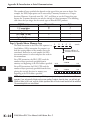
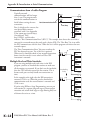
INTRODUCTION TO SERIAL
COMMUNICATIONS
A PPENDIX
PPENDIX
K
In this Appendix
Introduction to Serial Communications . . . . . . . . . . . . . . . . . . . . . .K–2
Appendix K: Introduction to Serial Communications
1
2
3
4
E
6
7
H
9
10
K
12
13
14
A
B
C
D
Introduction to Serial Communications
DirectLOGIC® PLCs have two built-in serial communication ports which can be used to
communicate to other PLCs or to other serial devices. In order to fully understand the
capabilities and limitations of the serial ports, a brief introduction to serial communications is
in order.
There are three major components to any serial communications setup:
Wiring standard
Communications protocol
Communications parameters
Each of these will be discussed in more detail as they apply to DirectLOGIC PLCs.
Wiring Standards
K–2
There are three different wiring standards that can be used with most of the DirectLOGIC
PLCs: RS-232C, RS-422 and RS-485. DL05 PLCs only support RS-232C, although RS-422
can be accomplished by using converters, such as the FA-ISOCON.
RS-232C is a point-to-point wiring standard with a practical wiring distance of 15 meters, or
50 feet, maximum. This means that only two devices can communicate on an RS-232C
network, a single master device and a single slave device, and the total cable length cannot
exceed 50 feet. AutomationDirect L19772 cable (Belden® 8102), or equivalent, is
recommended for RS-232C networks.
Ports 1 and 2 on the DL05 use RJ12 phone type connectors (see pages 4-4 and 4-5 for the
cable connections).
DL05 Micro PLC User Manual, 6th Edition, Rev. C
Appendix K: Introduction to Serial Communications
Communications Protocols
A communications protocol is the ‘language’ the devices on a network use to communicate
with each other. All the devices on the network must use the same communications protocol
in order to be able to communicate with each other. The protocols avaliable in the
DirectLOGIC DL05 PLCs are listed in the following table.
DL05 Communications Protocols
Protocol
Master
Slave
Port 1*
Port 2
RS-232C
RS-422
RS-485
K-Sequence
DirectNET
Modbus RTU
ASCII
No
Yes
Yes
Out
Yes
Yes
Yes
In
Yes
Yes
Yes
No
Yes
Yes
Yes
Yes
Yes
Yes
Yes
Yes
No
Yes**
Yes**
Yes**
No
No
No
No
* Port 1 supports slave only and is only RS-232C with fixed communications parameters of 9600
baud, 8 data bits, 1 start bit, 1 stop bit, odd parity and station address 1. It is an asynchronous, halfduplex DTE port and auto-selects between K-Sequence, DirectNET and Modbus RTU protocols.
** RS-422 is available on Port 2 using an RS-422 converter such as the FA-ISOCON.
K-Sequence protocol is not available for use by a master DL05 PLC. Therefore, it cannot be
used for networking between PLCs. Its primary use in the DL05 PLC is as a slave to
DirectSOFT programming software and to an operator interface.
DirectNET protocol is available for use by a master or by a slave DL05 PLC. This, and the
fact that it is ‘native’ protocol, makes it ideal for PLC-to-PLC communication over a pointto-point or multipoint network using the RX and WX instructions.
Modbus RTU protocol is a very common industry standard protocol, and can be used by a
master or slave DL05 to communicate with a wide variety of industrial devices which support
this protocol.
ASCII is another very common industry standard protocol, and is commonly used where
alpha-numeric character data is to be transferred. Many input devices, such as barcode readers
and electronic scales, use ASCII protocol. Many output devices accept ASCII commands as
well.
No matter which wiring standard or protocol is used, there are several communications
parameters to select for each device before it will be able to communicate. These parameters
include:
Baud Rate
Flow Control
Data Bits
Echo Suppression
Parity
Timeouts
Stop Bits
Delay Times
Station Address
Format
All of these parameters may not be necessary, or available, for your application. The
parameters used will depend on the protocol being used and whether the device is a master or
slave.
NOTE: An important point to remember is that when the same parameter is available in the master
and in the slave (i.e. Baud Rate, Parity, Stop Bits, etc), the settings must match.
DL05 Micro PLC User Manual, 6th Edition, Rev. C
1
2
3
4
E
6
7
H
9
10
K
12
13
14
A
B
C
D
K–3
Appendix K: Introduction to Serial Communications
1
2
3
4
E
6
7
H
9
10
K
12
13
14
A
B
C
D
Communications Port 2
DL05 Port Specifications
Communications Port 1
Connects to HPP, DirectSOFT 5, operator
interfaces, etc.
6-pin, RS232C
Communication speed (baud): 9600 (fixed)
Parity: odd (fixed)
Port 1 Station Address: 1 (fixed)
8 data bits
1 start, 1 stop bit
Asynchronous, half-duplex, DTE
Protocol (auto-select): K-sequence (slave only),
DirectNET (slave only), Modbus RTU (slave only)
K–4
Connects to HPP, DirectSOFT 5, operator
interfaces, etc.
6-pin, multifunction port, RS232C, RS422, RS485
(RS485 with 2-wire is only available for Modbus
and Non-sequence).
Communication speed (baud): 300, 600, 1200,
2400, 4800, 9600, 19200, 38400
Parity: odd (default), even, none
Port 2
Station Address: 1 (default)
8 data bits
1 start, 1 stop bit
Asynchronous, half-duplex, DTE
Protocol (auto-select): K-sequence (slave only),
DirectNET (master/slave), Modbus RTU
(master/slave), non-sequence/print
Port 1 Pin Descriptions
DL05 Port Pinouts
1
2
3
4
5
6
0V
5V
RXD
TXD
5V
0V
Power (-) connection (GND)
Power (+) connection
Receive data (RS-232C)
Transmit data (RS-232C)
Power (+) connection
Power (-) connection (GND)
1
Port 2 Pin Descriptions
1 0V
2 5V
3 TXD
4 RXD
5 RTS
6 CTS
Power (-) connection (GND)
Power (+) connection
Transmit data (RS-232C)
Receive data (RS-232C)
Ready to send (RS-232C)
Clear to send (RS232C)
1
Top View
Note that the default configuration for port 2 is:
Auto-detect among K-Sequence,DirectNET, and Modbus RTU protocols
Timeout = Base Timeout x 1 (800 ms)
RTS on delay time = 0 ms
RTS off delay time = 0ms
Station Number = 1
Baud rate = 19200
Stop bits = 1
Parity = odd
Format = Hex
DL05 Micro PLC User Manual, 6th Edition, Rev. C
Appendix K: Introduction to Serial Communications
Port Setup Using DirectSOFT or Ladder Logic Instructions
Port 2 on the DL05 can be configured for communications using the various protocols which
have been previously mentioned. Also, the communications parameters can be configured to
match the parameters in the other device(s) with which the PLC will be communicating. The
port may be configured using the DirectSOFT PLC programming software, or by using
ladder logic within the PLC program. It is important to note that the settings for port 2 are
never saved to disk with DirectSOFT, so if you are using port 2 in other than its default
configuration it is a good idea to include the port setup in the ladder program, typically on a
first scan bit, or in an initialization subroutine.
To set up port 2 using DirectSOFT, the PLC must be turned on and connected to
DirectSOFT. With the PLC Setup toolbar displayed, select the Port 2 button or select PLC >
Setup > Setup Sec. Comm Port... from the menu bar located at the top of the programming
window. A dialog box like the one below will appear. Make the appropriate settings and write
them to the PLC.
In order to set up port 2 in relay ladder logic the appropriate values must be written to
V7655 (Word 1), V7656 (Word 2) and V7650 (Word 3, for ASCII only) to specify the
settings for the port. Then write the ‘setup complete’ flag (K0500) to V7657 (Word 3) to
request the CPU to accept the port settings. Once the CPU sees the ‘setup complete’ flag in
V7657 it will test the port settings which have selected for validity, and then change the value
in V7657 according to the results of this test. If the port settings are valid, the CPU will
change the value in V7657 to 0A00 (‘A’ for Accepted). If there was an error in the port
settings, the CPU will change the value in V7657 to 0E00 (‘E’ for Error).
NOTE: This is a Helpful Hint. Rather than build the setup words manually from the tables, use
DirectSOFT to set up the port as desired then use a Dataview to view the setup words as BCD/HEX.
Then simply use these numbers in the setup code.
The data that is written to the port setup words has two formats. The format that is used
depends on whether K-Sequence, DirectNET, Modbus RTU (method 1) or ASCII (method
2) is selected.
DL05 Micro PLC User Manual, 6th Edition, Rev. C
1
2
3
4
E
6
7
H
9
10
K
12
13
14
A
B
C
D
K–5
Appendix K: Introduction to Serial Communications
Port 2 Setup for RLL Using K-Sequence, DirectNET or Modbus RTU
1
2
3
4
E
6
7
H
9
10
K
12
13
14
A
B
C
D
K–6
V7655 (Word 1)
RTS On-delay
Timeout
(% of timeout)
0yyy 0ttt mmmm mxxx
yyy
000 = 0ms
001 = 2ms
010 = 5ms
011 = 10ms
100 = 20ms
101 = 50ms
110 = 100ms
111 = 500ms
ttt
000 = 100%
001 = 120%
010 = 150%
011 = 200%
100 = 500%
101 = 1000%
110 = 2000%
111 = 5000%
V7656 (Word 2)
Parity
Stop Bits
Baud Rate
pp
00 = None
10 = Odd
11 = Even
s
0 = 1 bit
1 = 2 bits
bbb
000 = 300
001 = 600
010 = 1200
011 = 2400
100 = 4800
101 = 9600
110 = 19200
111 = 38400
V7656 (Word 2) cont’d
Protocol
Port 2 Address
K-Sequence, DirectNET
& Modbus RTU
pps0 0bbb xaaa aaaa
(DirectNET)
DirectNET and
Modbus RTU
aaaaaaa
DirectNET: 1-90
Modbus RTU: 1-247
K-Sequence, DirectNET
& Modbus RTU
pps0 0bbb xaaa aaaa
x
0 = Hex
1 = ASCII
DL05 Micro PLC User Manual, 6th Edition, Rev. C
Protocol
RTS Off-delay
mmmmm
10000 = K-Sequence
01000 = DirectNET
00100 = Modbus RTU
xxx
000 = 0ms
001 = 2ms
010 = 5ms
011 = 10ms
100 = 20ms
101 = 50ms
110 = 100ms
111 = 500ms
Appendix K: Introduction to Serial Communications
Use the ladder logic shown below to set up port 2 for Modbus protocol for the following:
RTS On-delay of 10ms, Base timeout x1, RTS Off-delay of 5ms, Odd parity, 1 Stop bit,
19,200 baud or Station Number 23.
SP0
LD
K3022
OUT
V7655
LD
K8617
OUT
V7656
Port 2 Setup for RLL Using ASCII
V7655 (Word 1)
RTS On-delay
Timeout
(in% of std. timeout)
0yyy 0ttt mmmm mxxx
yyy
000 = 0ms
001 = 2ms
010 = 5ms
011 = 10ms
100 = 20ms
101 = 50ms
110 = 100ms
111 = 500ms
ttt
000 = 100%
001 = 120%
010 = 150%
011 = 200%
100 = 500%
101 = 1000%
110 = 2000%
111 = 5000%
Protocol
RTS Off-delay
mmmmm
00010 = Non-Sequence
xxx
000 = 0ms
001 = 2ms
010 = 5ms
011 = 10ms
100 = 20ms
101 = 50ms
110 = 100ms
111 = 500ms
V7656 (Word 2)
Parity
Stop Bits
Baud Rate
K-Sequence, DirectNET
& Modbus RTU
pps0 0bbb aaaa aaaa
pp
s
bbb
00 = None
0 = 1 bit
000 = 300
10 = Odd
11 = Even
1 = 2 bits
001 = 600
010 = 1200
011 = 2400
100 = 4800
101 = 9600
110 = 19200
111 = 38400
DL05 Micro PLC User Manual, 6th Edition, Rev. C
1
2
3
4
E
6
7
H
9
10
K
12
13
14
A
B
C
D
K–7
Appendix K: Introduction to Serial Communications
1
2
3
4
E
6
7
H
9
10
K
12
13
14
A
B
C
D
K–8
V7656 (Word 2) cont’d
K-Sequence, DirectNET
& Modbus RTU
Protocol Mode
aaaaaaaa
01110000 = No flow control
01110001 = Xon/Xoff flow control
01110010 = RTS flow control
01110011 = Xon/Xoff and
RTS flow control
V7650 (Word 3)
V-memory address for data
Hex value of the V-memory location to
temporarily store the ASCII data coming into
the PLC. Set this parameter to an unused Vmemory location which has enough
consecutive memory locations free to store the
longest string that will come into the PLC.
Use the ladder logic shown below to set up port 2 for Non-sequence (ASCII)
communications with the following: RTS On-delay of 10ms, Base timeout x1, RTS Off-delay
of 5ms, Odd parity, 1 Stop bit, 19,200 baud, 8 data bits, V-memory buffer starting at V2000
and no flow control.
SP0
LD
K3012
OUT
V7655
LD
K8670
OUT
V7656
LDA
O2000
OUT
V7650
DL05 Micro PLC User Manual, 6th Edition, Rev. C
Appendix K: Introduction to Serial Communications
K-Sequence Communications
The K-Sequence protocol can be used for communication with DirectSOFT, an operator
interface or any other device that can be a K-Sequence master. The DL05 PLC can be a KSequence slave on either port 1 or port 2. The DL05 PLC cannot be a K-Sequence master.
In order to use port 2 for K-Sequence communications you first need to set up the port using
either DirectSOFT or ladder logic as previously described.
DirectNET Communications
The DirectNET protocol can be used to communicate to another PLC or to other devices
that can use the DirectNET protocol. The DL05 can be used as either a master using port 2
or a slave using either port 1 or port 2.
In order to use port 2 for DirectNET communications you must first setup the port using
either DirectSOFT or ladder logic as previously described.
For network slave operation, nothing more needs to be done. Port 2 will function as a slave
unless network communications instructions are executed by the ladder logic program.
For a network master operation you will simply need to add some ladder rungs using the
network communication instructions RX and/or WX. Only one network communication
instruction should be executed at any given time. If you have just a few network
communications instructions in your program, you can use discrete bits to interlock them. If
you are using many network communications instructions, a counter or a shift register will be
a more convenient way to interlock the instructions.
The following step-by-step procedure will provide the information necessary to set up your
ladder program to receive data from a network slave.
Step 1: Identify Master Port # and Slave #
The first Load (LD) instruction identifies the
communications port number on the network master
(DL05) and the address of the slave station. This
instruction can address up to 99 Modbus slaves, or 90
DirectNET slaves. The format of the word is shown to
the right. The “F2” in the upper byte indicates the use
of the the port on the right on the DL05 PLC, port
number 2. The lower byte contains the slave address
number in BCD (01 to 99).
Step 2: Load Number of Bytes to Transfer
The second Load (LD) instruction determines the
number of bytes which will be transferred between the
master and slave in the subsequent WX or RX
instruction. The value to be loaded is in BCD format
(decimal), from 1 to 128 bytes.
F
2
0
1
Slave address (BCD)
Port number (BCD)
Internal port (hex)
LD
KF201
6
4
(BCD)
# of bytes to transfer
LD
K64
DL05 Micro PLC User Manual, 6th Edition, Rev. C
1
2
3
4
E
6
7
H
9
10
K
12
13
14
A
B
C
D
K–9
Appendix K: Introduction to Serial Communications
1
2
3
4
E
6
7
H
9
10
K
12
13
14
A
B
C
D
The number of bytes specified also depends on the type of data you want to obtain. For
example, the DL05 Input points can be accessed by V-memory locations or as X input
locations. However, if you only want X0 – X27, you’ll have to use the X input data type
because the V-memory locations can only be accessed in 2-byte increments. The following
table shows the byte ranges for the various types of DirectLOGIC products.
DL05 Memory
Bits per unit
Bytes
V-memory
T / C current value
Inputs (X, SP)
Outputs
(Y, C, Stage, T/C bits)
Scratch Pad Memory
Diagnostic Status
16
16
8
2
2
1
8
1
8
8
1
1
Step 3: Specify Master Memory Area
K–10
The third instruction in the RX or WX sequence is a
Load Address (LDA) instruction. Its purpose is to
load the starting address of the memory area to be
transferred. Entered as an octal number, the LDA
instruction converts it to hex and places the result in
the accumulator.
For a WX instruction, the DL05 CPU sends the
number of bytes previously specified from its
memory area beginning at the LDA address specified.
For an RX instruction, the DL05 CPU reads the
number of bytes previously specified from the slave,
placing the received data into its memory area
beginning at the LDA address specified.
4
0
6
0
0
(octal)
Starting address of
master transfer area
LDA
O40600
MSB
V40600
LSB
0
15
MSB
15
V40601
LSB
0
NOTE: Since V-memory words are always 16 bits, you may not always use the whole word. For
example, if you only specify 3 bytes and you are reading Y outputs from the slave, you will only get
24 bits of data. In this case, only the 8 least significant bits of the last word location will be modified.
The remaining 8 bits are not affected.
DL05 Micro PLC User Manual, 6th Edition, Rev. C
Appendix K: Introduction to Serial Communications
Step 4: Specify Slave Memory Area
The last instruction in our sequence is the WX or RX
instruction itself. Use WX to write to the slave, and RX
to read from the slave. All four of our instructions are
shown to the right. In the last instruction, you must
specify the starting address and a valid data type for the
slave.
• DirectNET slaves – specify the same address in the WX
and RX instruction as the slave’s native I/O address
• Modbus DL05 slaves – specify the same address in the WX
and RX instruction as the slave’s native I/O address
SP116
LD
KF201
LD
K64
LDA
O40600
RX
Y0
DL05 Micro PLC User Manual, 6th Edition, Rev. C
1
2
3
4
E
6
7
H
9
10
K
12
13
14
A
B
C
D
K–11
Appendix K: Introduction to Serial Communications
Communications from a Ladder Program
1
2
3
4
E
6
7
H
9
10
K
12
13
14
A
B
C
D
Typically network
SP117
Y1
communications will last longer
SET
than 1 scan. The program must
SP116
wait for the communications to
LD
KF201
finish before starting the next
Port Communication Error
transaction.
LD
Port Busy
K0003
Port 2, which can be a master, has
two Special Relay contacts
LDA
O40600
associated with it (see Appendix
D for comm port special relays).
RX
One indicates “Port
Y0
busy”(SP116), and the other
indicates ”Port Communication Error”(SP117). The example above shows the use of these
contacts for a network master that only reads a device (RX). The “Port Busy” bit is on while
the PLC communicates with the slave. When the bit is off the program can initiate the next
network request.
The “Port Communication Error” bit turns on when the
Interlocking Relay
PLC has detected an error. Use of this bit is optional.
SP116 C100
LD
When used, it should be ahead of any network instruction
KF201
boxes since the error bit is reset when an RX or WX
instruction is executed.
LD
K0003
Multiple Read and Write Interlocks
K–12
If you are using multiple reads and writes in the RLL
program, you have to interlock the routines to make sure
all the routines are executed. If you don’t use the interlocks,
then the CPU will only execute the first routine. This is
because each port can only handle one transaction at a
time.
In the example to the right, after the RX instruction is
executed, C100 is set. When the port has finished the
communication task, the second routine is executed and
C100 is reset.
If you’re using RLLPLUS Stage Programming, you can put
each routine in a separate program stage to ensure proper
execution and switch from stage to stage allowing only one
of them to be active at a time.
LDA
O40600
Interlocking
Relay
SP116
C100
RX
VY0
C100
SET
LD
KF201
LD
K0003
LDA
O40400
WX
VY0
C100
RST
DL05 Micro PLC User Manual, 6th Edition, Rev. C
Appendix K: Introduction to Serial Communications
Modbus RTU Communications
The Modbus RTU protocol can be used for communication with any device that uses the
Modbus RTU protocol. The protocol is very common and is probably the closest thing to an
“industry standard” protocol in existence. The DL05 can be a Modbus RTU slave on either
port 1 or port 2, and it can be a Modbus RTU master on port 2.
In order to use port 2 for Modbus RTU communications you must first set up the port using
either DirectSOFT or ladder logic as previously described.
For network slave operation, nothing more needs to be done. Port 2 will function as a slave
unless network communications instructions are executed by the ladder logic program.
For network master operation the Modbus RTU network communication instructions MRX
and/or MWX must be added to the ladder program. If more than one network
communication instruction is used, the rungs need to be interlocked to ensure that only one
communication instruction is executed at any given time. If only a few network
communications instructions are used in your program, discrete bits can be used to interlock
them. If many network communications instructions are used, either a counter or a shift
register will be a more convenient way to interlock the instructions.
DL05 Micro PLC User Manual, 6th Edition, Rev. C
1
2
3
4
E
6
7
H
9
10
K
12
13
14
A
B
C
D
K–13