1
Fingertouch DMX Controller
P1L
User and Reference Manual
LUXURY
L IGHTING
APPLIANCES
P1L - User and Reference Manual
Page 2
This manual is meant for anybody who wish to use the LUX P1L Controller. It contains technical specifications, and describes
the connection, programming and how to properly configure and use the P1L.
Although all the information contained herein has been carefully verified, LUX Italia assumes no responsibility for errors that
might appear in this document, or for damage to property or persons resulting from an improper use of this manual and
of the related equipment. LUX Italia reserves the right to change the contents and form of this document, as well as the features
and specifications of its products at any time, without notice.
Trademarks and registered trademarks appearing in this document are the property of their respective owners.
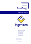
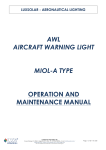
The P1L Packaging contents
Before to proceed, please verify contents of the P1L packaging contents:
1 - P1L DMX Controller
2 - Mounting Wall Plate
3 - User and Reference manual
and Limited Warranty Sheet
1
3
2
Fig. 1 - The P1L Package contents
Page 3
P1L - User Manual
Congratulations!
1.0 Introduction
You have chosen the world’s most sophisticated and refined
wall mounting full color light DMX controller. The P1L has a
plenty of features, such as:
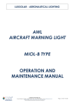
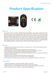
The P1L is full color finger touch DMX light controller for wall
mounting, shown on fig. 2:
?
Simple finger touch regulation
?
Full color light regulator
?
White color regulation
?
1 - 100% dimming control
?
Four User configurable program buttons
?
32KB User program memory space
?
DMX and OpenDMX protocol support
?
Master and Slave operation
?
8-30V AC/DC low voltage power supply
?
Isolated DMX bus
Your P1L has been designed and produced according to
highest LUX quality standards. In order to be able to use all
P1L functions, please read carefully this manual.
Fig. 2 - The P1L Controller
It implements a finger touch sensor to decode the movement
of the user finger and translate it into a color of the light. The
P1L can be used in any full color DMX and OpenDMX system,
but it is specially suitable for 4-channel LED lighting devices,
such as LUX lamps. It can drive directly DMX drivers
(operating in Master Mode), or it can be used as remote
control device for more complex systems (when running in
Slave Mode). The user dynamic light change programs can be
downloaded to the P1L using OpenDMX protocol. In that case
P1L will become full featured DMX controller unit.
P1L - User Manual
Page 4
1.1 Principle of operation
1.2 Configuration switches
Before to configure and install your P1L, you must
understand the principle of its operating within a DMX
system. The P1L can be installed in both DMX512A and
OpenDMX networks. In both cases, up to 9 different P1L can
be connected to the same trunk of DMX, but only one can be
configured as Master.
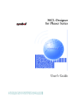
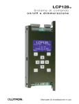
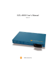
The P1L has ten configuration dip switches on the back panel.
Using those switches you can change the operating mode,
device address, communication protocol and so on.
ON
OFF
Master Mode
1 2 3 4 5 6 7 8 9 10
SW
In the Master Mode, P1L is the control device of the DMX
network. In this mode the whole DMX network is controlled by
Master P1L. If other P1 devices are connected to the same
network, all them must be configured as Slave devices. In
Master Mode P1L will continue to interrogate all other Slave
P1L present in the system.
DMX +
DMX GND
Power
Supply
Slave Mode
In the Slave mode, P1L will wat for the valid OpenDMX request
from the DMX bus, after wich it will reply with the current
status.
When used as a remote control device of the more complex
DMX network, P1L must be configured as a Slave.
Fig 3 - The P1L Connector and Dip Switch
1.2.1
Switch SW1 - DMX Line termination
This switch is used to enable DMX line termination. When
activated (in ON position), a 120 oHm resistor will be
connected between DMX+ and DMX- signals. Activate this
P1L - User Manual
Page 5
switch only in case when the P1L is physically the first or the
last device in the DMX network. For more information, please
refer to DMX512A specification.
functionality of the P1-P4 program button from static to
dynamic program and back. For more information on program
button functionality change, please refer to par. 2.6.
Factory default: OFF (120 oHm line termination disabled)
When the S4 is in ON position, the change of program buttons
will be disabled: user will not be able to change the usage of
the program buttons. The P1-P4 program button functionality
will remain the one selected before switch disable.
1.2.2
Switch SW2 - Master/Slave
The S2 is used to Configure P1L as a Master or a Slave device.
When configured as Master (S2 = OFF), P1L will drive whole
DMX network, while when configured as Slave (S2 = ON), P1L
will wait for the call of the other Master P1L on the network.
Factory default: OFF (P1L is a Master device)
1.2.3
Switch SW3 - Disable Stand By Function
The S3 is used to Enable / Disable Stand By function. The P1L
can be turned OFF by tipping twice over the front panel. You
can disable this function by placing switch S3 to ON.
Factory default: OFF (OFF/ON function enabled)
1.2.4
Switch SW4 - Program buttons change disable
The S4 is used to Enable / Disable P1-P4 program button
function change. When in OFF position, user can swap the
Factory default: OFF (Program button functionality can be
modified)
1.2.5
Switch SW5 - Child block disable
The S5 is used to Enable / Disable Child Block function. When
in Child Block state, no change of the light color and intensity
can be done. To disable Child Block, put S5 in ON. If Child
Block is active in that moment, it will remain active.
Factory default: OFF (Child Block toggle Enabled)
P1L - User Manual
1.2.6
RGBW mode
Switch SW6-7 - Color Mode Selection
The S6 and S7 switches are used to select output color mode:
Mode
S6
S7
RGBY
RGB
RGBW
RGB-8
OFF
ON
OFF
ON
OFF
OFF
ON
ON
4
3
4
3
channel
channel
channel
channel
Page 6
R,G,B,Y. 4 DMX addresses
R,G,B. 3 DMX addresses
R,G,B,W. 4 DMX addresses
R,G,B. 8 DMX addresses
In RGBW mode, the fourth channel will be the support to white
color. The DMX frame will have the following contents:
0
1
2
3
4
5
6
7
...
n-2
n-1
n
R
G
B
W
R
G
B
W
...
G
B
W
RGB - 8 mode
RGBY mode
In RGBY mode P1L will generate 4 color schematic. All colors
will be created using standard RGB with the addition of
Yellow. The DMX frame will have the following contents:
0
1
2
3
4
5
6
7
...
n-2
n-1
n
R
G
B
Y
R
G
B
Y
...
G
B
Y
This mode has been created for a compatibility purpose. In
this mode each lamp will be allocated with 8 bytes. First three
bytes will contain RGB information. Fourth byte is fixed value,
0xFF. Other three bytes are 0x00:
0
1
2
3
4
5
6
7
...
n-2
n-1
n
R
G
B
255
0
0
0
0
...
0
0
0
1.2.7 Switch SW8 in Master mode - OpenDMX Enable/Disable
RGB mode
RGB mode is the basic color mode. The DMX frame will have
the following contents:
0
1
2
3
4
5
6
7
...
n-2
n-1
n
R
G
B
R
G
B
R
G
...
R
G
B
In Master mode there is a possibility to connect up to 9 P1L to
the same DMX network. Their communication is done via
OpenDMX protocol.
The majority of DMX drivers on the market are respecting
DMX512A specification. In those cases OpenDMX protocol
Page 7
P1L - User Manual
used for inter-P1L communication will not create any
problem. Unfortunately, not all drivers present on the market
are respecting completely DMX512A specification. When
using those drivers, OpenDMX protocol will create flickering
problems.
To avoid those problems, you can disable OpenDMX protocol.
Please note that when you disable OpenDMX protocol, you
will not be able to drive any slave device or to do the User
program Download. To dowload User dynamic programs,
enable temporary OpenDMX protocol, do the programming
using LX630 USB/DMX interface and disable again OpenDMX.
To disable OpenDMX protocol, switch ON the S8.
Factory default: OFF (OpenDMX enabled)
1.2.8 Switch SW8 in Slave mode - Slave Address Selection
Refer to Par. 1.2.12
1.2.9 Switch SW9 in Master mode - Channel 0 position
This switch has a different purpose in Master and Slave mode.
This switch select the position of the Channel 0. When in OFF
position, DMX channel sequence will start from the byte 1,
while when in ON, it will start from the byte 2:
SW9 = OFF
0
1
2
3
...
R
G
B
R
...
SW9 = ON
0
1
2
3
4
...
0
R
G
B
R
...
Factory default: OFF (Channel 0 is on the 1st position)
1.2.10 Switch SW9 in Slave mode - Slave Address Selection
Refer to Par. 1.2.12.
1.2.11 Switch SW10 in Master mode - Frame length
This switch has a different purpose in Master and Slave mode.
Standard DMX512A frame can have up to 513 bytes (control
byte and 512 channels). When used all channels, 44 frames
per second can be transmitted. This frame rate is very low for
fine light regulation.
P1L - User Manual
In those cases when a reduced number of lamps is used, a 64
channel mode can be selected. In this mode up to 21 different
RGB lamps can be controlled, with the frame rate on 333
transmission per second can be obtained, offering 256 levels
smooth dimmering.
Factory default: OFF (64 channel frame length)
1.2.12 Switch SW8,9,10 in Slave mode
Slave Address Selection
In slave mode, switches 8, 9 and 10 are used to select Slave
device address:
Up to nine P1L devices can be connected to the same DMX
network. One of them must be configured as MASTER, while
all other will be configured as SLAVES. Each slave must have
an unique address in the network. Using S8, S9 and S10
switches, you can select addresses from 0 to 7. Note that it is
not important which device get which address. The important
is that there must not be address overlap.
Page 8
Device address
S8
S9
S10
Address
Address
Address
Address
Address
Address
Address
Address
OFF
ON
OFF
ON
OFF
ON
OFF
ON
OFF
OFF
ON
ON
OFF
OFF
ON
ON
OFF
OFF
OFF
OFF
ON
ON
ON
ON
0
1
2
3
4
5
6
7
1.3 Power Supply
The P1L can be powered by either AC or DC low voltage power
supply. Although the power required by P1L is rather low, it is
very important that the power supply used to power P1L must
be reliable to guarantee continuous supply of the electric
energy to the device.
If used AC power supply, the range from 6 to 26V can be
applied. If used DC power supply, you can use range from 8 to
36V DC. In both cases, consumption is below 0.6W. The
polarity of the DC power supply doesn’t matter.
Page 9
P1L - User Manual
1.4 DMX connection
2.0
The P1L has bi-directional DMX interface. The DMX port is 2.0
P1L Usage
The usage of the P1L is rather intuitive. Yet, there are some
functions that are almost “hidden”, so it is important to read
carefully following paragraphs.
The usage of the P1L is rather intuitive. Yet, there are some
functions that are almost “hidden”, so it is important to read
carefully following paragraphs.
2.1
P1L Usage
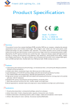
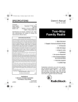
Front panel description
The figure 4 shows P1L front panel:
2.1 Front panel description
The figure 4 shows P1L front panel:
physically separated from the rest of the electronic. There is
also integrated line termination resistor (see par. 1.2.1).
Note that DMX network is polarized network. We recommend
the twisted, shielded, 2 x 22 AWG cable. Use only high quality
cables for the connection.
Stand By LED
Program 1,2,3,4 LEDs
Dimmer
Area
Color
Selection
Area
1.5 Device Installation
Before to connect device to the system, ensure that all other
devices are switched OFF, and that the power supply cable
dedicated to the P1L is without power.
Configure device according to the instructions from par. 1.2.
LUX Logo
Program
Buttons
P1L - User Manual
2.2
Switching the system OFF/ON
In OFF condition the Stand by LED is illuminated briefly. This
very low level light is used to indicate the position of the P1L
in the dark.
To switch ON the P1L, just touch the surface of the front
panel, without taking care about the position of the finger.
The P1L will turn ON the light using the last configuration
before the switch OFF. This means that if you set the red color
light and then turn OFF the light, when you will turn ON again,
P1L will restore the red color light.
To switch OFF, you have to tip twice the surface of the front
panel of the P1L. Note that if you remain for the long time in
contact with the front panel, you will have to repeat the
procedure of switching OFF. In order to be decoded as switch
OFF command, your first tip must not take more then 150 mS,
and the next one must arrive within 300 mS from the first one.
When switched ON, Stand by LED is illuminated with the full
intensity, indicating that the system is activated.
The P1L will memorize the light color and intensity 2 seconds
from the last finger touch, even if not turned OFF. In case of
black-out, when the energy will return, the P1L will restore
Page 10
the last light scheme.
2.3
Light color regulation
To regulate light color, touch the colored area of the front
panel over desired color. Note that you must not remove the
finger from the panel before expiring the period of 150 mS,
otherwise P1L will think that you want to turn it OFF.
The colored area is divided in two regions - colored and white
region:
The white area is used to regulate white light color. Even if
not indicated, this area is divided in different levels of the
white color, as indicated in figure:
Page 11
P1L - User Manual
When you point to the center of the white circle, the P1L will
regulate to the full white color. By moving the finger to the
red color, light will start to change from white to the white/red
color. In this way you can trim your white color as you like.
2.4
Light intensity regulation
The P1L has a dimmer area used to regulate light intensity.
The dimmer is capable to modify light intensity from 1 to
100%, regardless of the selected color.
To regulate light intensity, simply point the finger over
dimmer area.
2.5
Child block - protected mode
The P1L has a special feature of protection against undesired
color regulation. In this mode, you will be able to turn it
OFF/ON and nothing else.
In order to enter protect mode, touch and keep the finger
over LUX logo for more then 6 seconds. After 2 seconds,
green Stand by LED will start to blink. When 6 seconds period
is expired, Stand by LED will stop to blink and P1L will enter
protected mode.
In protected mode there will be no possibility to modify light
color, intensity or to choose programs. The P1L will behave as
a simple OFF/ON switch, using the light color and intensity
selected before the entrance to the protected mode.
To exit the protected mode, repeat the same procedure used
to enter the protected mode.
2.6
Program modes
The P1L has four user program buttons, indicated with P1-P4.
Those buttons are used to select user program, and to
memorize particular light settings. When one of the programs
is selected, a red LED indicator is lit ON.
To memorize one light settings, just press the program button
for more then 3 seconds. When pressed a program button,
red LED indicator will start to blink rapidly. After 3 seconds it
will start to blink slowly, indicating that the new settings has
been memorized. You can continue to memorize new settings
over the previous one.
To select one of the four programs, just press the program
button for less then 3 seconds. A program LED indicator will
switch ON.
To exit program mode, press the color selection area.
P1L - User Manual
The P1L can memorize up to four dynamic color changing
programs. Those programs can be downloaded via DMX bus
from an external remote controller unit, such as PC. For more
information on how to create user programs, refer to the
technical reference section in this manual and to L.E.T. LX630 USB/DMX Software manual.
Once when downloaded, user programs will be memorized
“below” the color settings programs. To select dynamic
programs, press and keep pressed program button for more
then 6 seconds. During this period, red LED indicator will
start to blink rapidly for the first 3 seconds, and then it will
continue to blink slowly for the next 3 seconds. At the end of
the 6 seconds period, it will stop blinking and fix the light ON,
indicating that a new program mode has been selected.
When memorized new light settings by pressing the program
button for 3 seconds, a dynamic program is not lost, but
rather it will be “pushed” to the background. To recall the
dynamic program, just press the program button for 6
seconds.
During dynamic program execution, it is possible to regulate
program execution speed. For that purpose a dimmer area is
used. The program execution speed can be regulated from
Page 12
10% up to 250% of the original speed. The regulated speed
will remain for all programs until device will be placed in
stand by (OFF).
2.7
Maintenance
The P1L does not need the special, particular care. Although,
it is important to follow some simple cautions in order to
guarantee long operating life.
Never clean the device with wet duster, water or any other
liquid. To remove dust, use only clean and dry duster.
P1L - Technical Reference
Page 13
P1L Technical Reference
1.0
Introduction
This section gives the full information about P1L technical
features, and it is meant for system integrators, installers
and other technical personal.
The P1L is finger touch color regulator and DMX controller.
The core of the device is a custom 16-bit MCU, implementing
DMX512A and OpenDMX. The latter is based on DMX512A, but
offers more possibilities such as file transfer, synchronous
operation, and diagnostics, and it is a public-domain, licensefree document. For more information about OpenDMX
protocol, please refer to www.luxitalia.eu.
The MCU uses a proprietary algorithm to translate finger
position on the color wheel into a DMX signal, with a response
time of 40 Hz. Four channels – red, green, blue and yellow –
are used, called RGBY color scheme.
1.1
dimmer settings, and at the end a final four channel
information is transmitted using DMX512A protocol.
DMX512A Data Transfer
During regulation, finger position is translated into four
channel color scheme - Red, Green, Blue and Yellow (RGBY).
Then, the color intensity is calculated according to the
The standard DMX512A protocol offers 512 bytes for a data
transfer. The P1L will send the following DMX frame:
Byte 0
Byte 1
Byte 2
Byte 3
Byte n-3 Byte n-2 Byte n-1 Byte n
Red
Green
Blue
Yellow
Red
Green
Blue
Yellow
As shown, the same information is repeated every four
channels. The first byte transmitted is Red, then Green, Blue
and Yellow. Using dip switch S2.6 you can select to skip the
first byte (byte 0) of the DMX frame (that will have value 0),
used as service byte, and then transmit the data frame as
shown:
Byte 0
0
Byte 1
Byte 2
Byte 3
Byte n-3 Byte n-2 Byte n-1 Byte n
Red
Green
Blue
Red
Green
Blue
Yellow
The length of the DMX512A frame is defined using dip switch
S2.4 and S2.5.
1.2
OpenDMX Data Transfer
When operating using OpenDMX protocol, the P1L will use
P1L - Technical Reference
following command set:
Color settings command:
Stand by mode:
Program transfer:
Slave switch inquery:
ODMX_SETPWM
ODMX_STDBY
ODMX_FILESEND
ODMX_GETSWITCH
All light regulation commands will be transmitted as
BROADCAST message.
1.2.1
Light Regulation - ODMX_SETPWM
Page 14
refresh to the network. During stand by mode, the
ODMX_GETSWITCH frame will continue to exist with the same
frequency as during active mode.
1.3
The P1L Programming
The P1L is a full DMX control central unit that can memorize
up to four different user programs. The programming is done
via DMX network and using OpenDMX protocol. Only P1L in
MASTER mode can be programmed.
For ODMX_SETPWM command, the P1L will use 8 bit data
transfer. Lower 8 bits will be used to transmit color intensity
from 0 to 255, while upper 8 bits will be 0.
The user program has a specific defined structure described
here below. Four user programs must be joined in one file
that will be transferred to P1L as described after.
The PWM_DATA structure will have following meaning:
PWM_DATA.Channel_1 = Red color
PWM_DATA.Channel_2 = Green color
PWM_DATA.Channel_3 = Blue color
PWM_DATA.Channel_4 = Yellow color
1.3.1
1.2.1
Stand by mode - ODMX_STDBY
The Stand by command will be send during OFF/ON of the
P1L. When in OFF condition (stand by mode activated), P1L
will send ODMX_STDBY command frame every 1 second as
Programming Mechanism
The Master P1L will issue a ODMX_SRVREQ frame every 900
mS. The remote PC (or other device) must answer within 10
mS with ODMX_SRVANW command where SERVICE_ID must be
set to 0x01. At this point, P1L will stop any other activity
(including finger sensing) for the next 10 mS. If within this
time remote PC will start file transfer, the P1L will start to
receive data. At the end of the file transfer, P1L will restart
with the normal activity.
P1L - Technical Reference
Page 15
1.3.2
Program structure
User program structure has the following format:
Address
0x00
0x02
0x04
0x06
Length
0x02
0x02
0x02
0x02
0x08
0x10
0x02
----
typedef struct {
BYTE
BYTE
INT
INT
BYTE
}RECORD;
Description
Record size
Address offset of the program
Number of records in the program
CHNNUM (Number of channels
of the in the record structure)
Total size of the story (header excluded)
Records[...]
RecordType;
Parameter;
FadeTime;
WaitTime;
Outputs[CHNNUM];
You must transfer four programs all together. The first to be
transfered is all four program headers, then all records.
For more information about program structure and the
meaning of each parameter, please refer to the OpenDMX
specification.
Note that total length of the four programs cannot exceed
31KB, and that max. CHNNUM = 512 (171 RGB lamps or 128
RGBY/RGBW lamps)
1.3.3
File transfer
File transfer will occur after ODMX_SRVANW frame
transmission. The USER PROGRAM file cannot be longer then
31 KB and must contain all four user programs. User program
can have no records. In that case program button on P1L will
be continuously used to memorize static color set.
The file will be transferred using standard ODMX_FILESEND
command, with the FileType filed set to 0.
P1L - Technical Reference
1.4
Technical Data
Power supply range
1.5
DMX interface isolation
DMX Refresh rate
6 ... 26 V AC
+8 ... 36 V DC
1.3 W
1.1 W
100V
44 Hz
CPU
User program memory
16 bit RISC
32 KB
Power consumption
AC
DC
Active mode
Stand By mode
Page 16
Troubleshooting Guide
Green LED is ON, but
when touching the pad
there is no regulation
The P1L might be in “Child Block”
mode. See par. 2.5
When connected to the
The lamp drivers you are using
DMX network, light
are not compatible to the
is flickering and strobing original DMX specifications.
You must use drivers that
recognize ZERO START code
and not ignoring it.
When selecting Green
color, light become
RED, Blue is Green and
so on
Try to switch Channel Zero
position. See par. 1.2.9
When connect more P1L
to the same network, no
one of them is working
properly
Only one of them must be a
MASTER device, while all other
must become SLAVE.
See par. 1.1
If you cannot resolve the problem, contact [email protected]
Page 17
P1L - Technical Reference
Table of contents
P1L USER MANUAL
1.0
Introduction
3
1.1
Principle of operation
4
1.2
Configuration switches
4
1.2.1 Switch 1 - DMX Line termination
4
1.2.2 Switch 2 - Master/Slave
5
1.2.3 Switch 3 - Disable Stand By Function
5
1.2.4 Switch 4 - Program buttons change disable
5
1.2.5 Switch 5 - Child block disable
5
1.2.6 Switch 6-7 - Color Mode Selection
6
1.2.7 Switch 8 in Master mode - OpenDMX Enable/Disable 7
1.2.8 Switch 8 in Slave mode - Slave Address Selection
7
1.2.9 Switch 9 in Master mode - Channel 0 position
7
1.2.10 Switch 9 in Slave mode - Slave Address Selection
7
1.2.11 Switch 10 in Master mode - Frame length
7
1.2.12 Switch 8,9,10 in Slave mode Slave Addr. Selection 8
1.3
Power Supply
8
1.4
DMX Connection
9
1.5
Device installation
9
2.0
P1L Usage
9
2.1
Front panel description
9
2.2
Switching the system OFF/ON
10
2.3
2.4
2.5
2.6
2.7
Light color regulation
Light intensity regulation
Children block - protected mode
Program modes
Maintanance
10
11
11
11
12
P1L TECHNICAL REFERENCE
1.0
1.1
1.2
1.2.1
1.2.2
1.3
1.3.1
1.3.2
1.3.3
1.4
1.5
Introduction
DMX512A Data Transfer
OpenDMX Data Transfer
Light regulation - ODMX_SETPWM
Stand by mode - ODMX_STDBY
The P1L Programming
Programming mechanism
Program structure
File transfer
Technical data
Troubleshooting guide
13
13
13
14
14
14
14
15
15
16
16
Notes
Page 18
Page 19
Notes
LUXURY
L IGHTING
APPLIANCES
LUX Italia
Via Firenze 18
20060 Trezzano Rosa
Milan, ITALY
Phone ++39 02 9202 0427
Fax ++39 02 9096 7253
e-mail: [email protected]
Copyright © LUX Italia 2008 - All rights reserved - www.luxitalia.eu - Printed in Italy