1
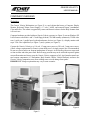
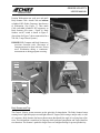
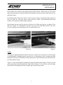
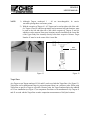
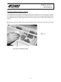
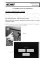
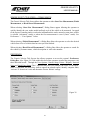
Genesis Velocity
Measuring System
USERS MANUAL
2002 © Chief Automotive Systems, Inc.
GENESIS VELOCITY
USERS MANUAL
Table Of Contents
I.
INTRODUCTION
GENESIS VELOCITY LIMITED WARRANTY AGREEMENT
GENERAL OVERVIEW
About This Manual
Training
VARIANCES: GRAPHICS / SPECIFICATIONS
Specifications Versus Vehicle Measurements
GENERAL SAFETY INFORMATION
Controls
Laser Safety Information
Federal Communications Commission
COPYRIGHT INFORMATION
Genesis Velocity Users Manual
Genesis Velocity Software
GENESIS VELOCITY ASSISTANCE
II.
GENESIS VELOCITY HARDWARE
COMPONENT TERMINOLOGY
COMPONENT OVERVIEWS
Workstation
Body Scanner and Tray
Targets
Target Base
Attachments / Clips / Extensions
Magnetic Attachments
Bolt Attachments
Hole Attachments
Extensions
Upper Body Bar Assembly
Spacers and 3 Inch Bolts
Chief Specifications Data
Literature
Diskettes and CDs
COMPONENT MAINTENANCE
COMPONENT TROUBLESHOOTING
III.
GENESIS VELOCITY PROGRAM
STARTING UP GENESIS VELOCITY SYSTEM
GENESIS VELOCITY WINDOWS AND MENUS
SHUTTING DOWN GENESIS VELOCITY SYSTEM
WINDOWS
DIALOG BOXES
VEHICLE GRAPHICS
KEYBOARD, MOUSE AND PEN
SPECIAL KEYS
GENESIS VELOCITY WINDOWS AND MENUS
HELP TEXT
HOW TO USE HELP
GENESIS VELOCITY TUTORIAL
GENESIS VELOCITY WIZARD
1
1
1
1
2
2
3
3
3
4
4
4
4
5
6
6
7
7
8
9
10
11
11
12
12
13
14
16
16
16
17
18
20
21
21
23
23
24
26
28
30
33
35
36
38
40
40
GENESIS VELOCITY
USERS MANUAL
I. INTRODUCTION
GENERAL OVERVIEW
Whether detecting misalignment in a vehicle’s structure or verifying repairs have eliminated the damage, Genesis computerized measuring system can do the job. Genesis integrates the precision of laser
scanning with a computerized data base for unmatched accuracy in collision repair and analysis. In
addition to showing extent of collision damage, Genesis monitors progress throughout the repair and
verifies the vehicle’s structure is correctly aligned. Printed reports verify the vehicle’s structural condition by showing overhead diagrams that display centerline, datum line and datum height measurements.
The Genesis system measures on the principle of triangulation. The system’s electronic Body Scanner
houses Laser Lights that reflect off of revolving mirrors toward light-reflective Targets (each bearing
a unique code) that are suspended from vehicle’s reference points. The Body Scanner houses photo
sensors that identify the angle of revolving laser reflections. This information is transferred to the computer which performs the triangulation and Target identification functions.
About This Manual
This manual provides information on basic hardware components. It also provides pertinent information regarding startup/shutdown procedures, examples of on-screen Windows/Dialog Boxes and
Vehicle Graphics, Keyboard/Mouse/Pen functions, Special Keys, and information on how to use the
Genesis Help Text. Pertinent software functions and parts ordering information appear in the Genesis
Basic Training Manual and Genesis Parts Manual.
Chief Automotive Systems, Inc. reserves the right to alter product specifications and/or package
components without notice. Also, components shown in this manual may vary slightly in
appearance from those that are actually supplied with the Genesis computerized measuring system.
Training
Chief Automotive Systems, Inc. also offers professional training. For maximum productivity and
equipment utilization, each person operating a Genesis computerized measuring system should receive
training conducted by Chief Training Department personnel. For information about training locations
and dates, contact Chief Automotive Systems, Inc., P.O. Box 1368, 1924 East Fourth St., Grand Island,
Nebraska 68802-1368, 308/384-9747, Attn: Training Department School Coordinator or contact your
local representative.
1
GENESIS VELOCITY
USERS MANUAL
GENESIS VELOCITY COMPUTERIZED MEASURING SYSTEM LIMITED WARRANTY AGREEMENT
Chief Automotive Systems, Inc. warrants for one year from date of purchase any components of its Genesis Velocity
Computerized Measuring System and three years for its Genesis Velocity Computerized Measuring System which do not perform satisfactorily due to defect caused by faulty material or workmanship. THE WARRANTY DESCRIBED HEREIN
SHALL BE IN LIEU OF ANY OTHER WARRANTY, EXPRESS OR IMPLIED, INCLUDING BUT NOT LIMITED TO,
ANY IMPLIED WARRANTY OF MERCHANTABILITY, OF FITNESS FOR A PARTICULAR PURPOSE, OF TITLE, OR
OTHERWISE ON THE PART OF CHIEF AUTOMOTIVE SYSTEMS, INC. AND MITCHELL INTERNATIONAL
REGARDING THE EQUIPMENT, THE SPECIFICATIONS CONTAINED THEREIN OR ANY UNIT THEREOF. Chief's
obligation under this warranty is limited to the repair or replacement of components which are defective and which have not
been misused, carelessly handled, or defaced by the repair or repairs made or attempted by others. Chief Automotive Systems,
Inc. does not assume responsibility for any injury or property damage resulting from the operator's misuse of this product.
Unless a statement made by any representative of Chief Automotive Systems, Inc. is identified as a warranty, any such statements shall not be construed to constitute warranties and do not form part of the basis of the bargain; it being expressly understood that such statements are merely made in the course of the negotiations of the parties. FURTHERMORE, Chief
Automotive Systems, Inc. specifically excludes or disclaims any warranty, express or implied, based on any sample or model
shown by Chief Automotive Systems, Inc. to the buyer for demonstration purposes only.
LIMITATION OF REMEDIES. The parties agree that the buyer's sole and exclusive remedy against Chief Automotive
Systems, Inc. shall be for the repair or replacement of components which are defective and which have not been misused, carelessly handled, or defaced by the repair or repairs made or attempted by others. The buyer agrees that no other remedy (including, but not limited to, incidental or consequential damages for lost profits, lost sales, injury to person or property, or any other
incidental or consequential loss) shall be available to him. This exclusive remedy shall not be deemed as to have failed of its
essential purpose so long as Chief Automotive Systems, Inc. is willing and able to repair or replace defective parts in the prescribed manner.
Prior to the return of any merchandise for a warranty claim, contact the Customer Service Department (800-445-9262)
for a Returned Goods Authorization Number and instructions. No goods may be returned without a Returned Goods
Authorization Number.
The buyer shall be required to deliver the defective part to Chief Automotive Systems, Inc. UNLESS (1) the part was destroyed
as a result of its defect or of any defect in any part covered in this warranty, AND (2) Chief is reasonably satisfied that the part
was defective at the time of its failure.
DISCLAIMER OF WARRANTY
THE GRAPHICS AND DATA SUPPLIED WITH THE GENESIS VELOCITY SYSTEM HAVE BEEN COMPILED
FROM AUTHORITATIVE SOURCES. EVERY EFFORT HAS BEEN MADE BY CHIEF AUTOMOTIVE
SYSTEMS, INC., TO ASSURE ACCURACY; HOWEVER, MANUFACTURING CHANGES, ERRORS OR OMISSIONS MIGHT OCCUR. CHIEF AUTOMOTIVE SYSTEMS, INC. DOES NOT ASSUME RESPONSIBILITY NOR
CAN IT BE HELD RESPONSIBLE FOR THE LOSS OR DAMAGE RESULTING FROM VEHICLE MANUFACTURER'S CHANGES, ERRORS, OR OMISSIONS IN THIS SYSTEM.
GENESIS VELOCITY COMPUTERIZED MEASURING SYSTEM WARRANTY REGISTRATION FORM
Please fill out completely and detach from Genesis Velocity Users Manual. Return form to:
Chief Automotive Systems, Inc., Box 1368, Grand Island, Ne. 68802-1368
Accepted this __________ day of ___________________________________, 20 _____.
Serial Numbers:
System ______________________
Shop Name: __________________________________________________
Body Scanner ________________
Address: _____________________________________________________
Computer____________________
City, State, Zip: ________________________________________________
Monitor______________________
By: _________________________________________________________
Printer_______________________
Title: ________________________________________________________
GENESIS VELOCITY
USERS MANUAL
VARIANCES: GRAPHICS/SPECIFICATIONS
Graphics
The Graphics displayed by the Genesis Velocity computerized measuring system are of high quality and
have been checked for accuracy, but may not reflect the vehicle’s actual appearance in every detail.
Variances may exist as a result of changes made by vehicle manufacturers or details omitted as a result of
space limitations.
Specifications Versus Vehicle Measurements
A vehicle’s final measurements may vary from specifications listed and still be aligned correctly. Variances
between vehicle measurements and specifications result from one or a combination of the following conditions:
• Vehicle specifications are compiled from vehicle manufacturer’s engineering drawings and/or the measuring of new (undamaged) vehicles.
• Most vehicle manufacturers control only a small number of reference points on vehicle’s lower structure.
These reference points are commonly referred to as master control points, class one control points, principle locating points, etc. Each of these control points is usually held to a tolerance of plus or minus 3mm
in three dimensions (length, width, height). Other reference points have a larger tolerance, but generally, a tolerance of plus or minus 5mm in three dimensions (length, width, height) is considered ‘normal’
according to Chief Automotive Systems, Inc. experience. In Arrow Display Mode, reference point measurements that exceed tolerance appear in ‘red’ whereas those falling within tolerance appear in ‘blue’.
• Some reference points used for dimensioning the same make and model of vehicle vary from one manufacturing plant to another. Also, periodic manufacturing improvements can affect the location of points
used for dimensioning.
Key points to remember when realigning a vehicle:
• Length and width dimensions on each side of vehicle should be within plus or minus 3mm of each other
when control or reference points are symmetrical. Frequently, the height at front and rear of vehicle will
exceed this tolerance according to Chief Automotive Systems, Inc. experience.
• When excessive pressure is needed near end of realignment process, and when area around spot welds
begins to deform, ‘stop pulling’ and ‘re-evaluate the repair’. This situation usually occurs when a vehicle’s components were not placed on specification during manufacture. In this case, continuing to pull in
an attempt to achieve an exact specification may actually damage the vehicle.
• When a vehicle’s dimensions vary beyond ‘normal’ tolerances, it is the repair technician’s responsibility to determine if dimensional variances will affect suspension and steering alignment, the safe operation
and handling of vehicle, and alignment of body panels.
2
GENESIS VELOCITY
USERS MANUAL
GENERAL SAFETY INFORMATION
CAUTION: Use of controls or adjustments or performance of procedures other than those specified in this Users Manual may result in hazardous radiation exposure. See CAUTIONS on Workstation and Body Scanner. (See illustration below.)
IMPORTANT:
DO NOT plug the Genesis Velocity system into same line as a welder. The built-in
surge protector may not be sufficient to protect against current fluctuations that
result from welder use, and it may cause the computer to fail. Also, avoid metal-tometal contact between all components (i.e. Workstation, Body Scanner, Welder,
Vehicle Platform).
Controls
“On”/“Off” switch on Workstation — Allows power to Computer and other electrical components.
On/off switch on Body Scanner — Allows power to Body Scanner including lasers.
Laser Safety Information
NOTE: Genesis System is for indoor use only.
Laser Power Output:
1.9 mw @ 4.2 x 10⁻⁴ sec.
Wavelength:
650 - 670 n Meters
LASER RADIATION-DO NOT
STARE INTO BEAM
WORKSTATION
PEAK POWER
1.9 MW
WAVELENGTH
670 nm
CLASS II LASER PRODUCT
BODY SCANNER
Power
“On”
Indicator
NOTE: Properly licensed / certified
electrician needed to install
the appropriate power cord
plug end on main Genesis
power cord set.
Always turn
scanner off
before disconnecting.
Laser
Emissions
Laser Reflections
CAUTION: Avoid exposure! Laser
radiation is emitted from Body Scanner
apertures.
3
GENESIS VELOCITY
USERS MANUAL
General Safety Information (continued)
Federal Communications Commission
The Genesis Velocity computerized measuring system has been tested and found to comply with: 1)
Limits for a Class A digital device, pursuant to Part 15 of the FCC Rules. 2) CE standards for emissions (EN55011) and Immunity (EN61326). These limits are designed to provide reasonable protection against harmful interference when equipment is operated in a commercial environment. This
equipment generates, uses, and can radiate radio frequency energy and, if not installed and used in
accordance with users and training manuals provided, may cause harmful interference to radio communications. Operation of this equipment in a residential area is likely to cause harmful interference in
which case the user will be required to correct the interference at his own expense.
COPYRIGHT INFORMATION
Genesis Velocity Users Manual
Chief Automotive Systems, Inc. © 1999. All Rights Reserved. No part of this work covered by copyrights hereon may be reproduced or copied in any form or by any means including, but not limited to,
graphics, electronic, or mechanical, including photocopying, taping, printing or information storage
and retrieval systems — without written permission of Chief Automotive Systems, Inc., Grand Island,
Nebraska, U.S.A. All inquiries relating to use of this information should be addressed to Chief
Automotive Systems, Inc., Tel (+) 800-445-9262, Fax (+1) 308-384-8966.
Genesis Velocity Software
Chief Automotive Systems, Inc. © 1999. All Rights Reserved. No part of this work covered by copyrights hereon may be reproduced or copied in any form or by any means including, but not limited to,
graphics, electronic, or mechanical, including photocopying, taping, printing or information storage
and retrieval systems — without written permission of Chief Automotive Systems, Inc., Grand Island,
Nebraska, U.S.A. All inquiries relating to use of this information should be addressed to Chief
Automotive Systems, Inc., Tel (+) 800-445-9262, Fax (+1) 308-384-8966.
Portions © Iterated Systems, Inc. 1990-1993. All Rights Reserved. Fractal image compression and
decompression are covered by U.S. patents and other international patents belonging to Iterated
Systems, Inc. All inquiries relating to use of the technology should be addressed to Iterated Systems,
Inc. Tel (+1) 404-840-0633, Fax (+1) 404-840-0806.
4
GENESIS VELOCITY
USERS MANUAL
GENESIS VELOCITY ASSISTANCE
Chief Automotive Systems, Inc. offers assistance to Genesis Velocity program operators. When contacting Chief Automotive Systems, Inc., operators should be prepared to give their name, telephone
number (including area code), version of software in use and nature of problem encountered. To identify version of software in use, select ‘About’ from list of items under Help heading in any Menu Bar.
In U.S.A., call toll free 800-445-9262, ext. 333. If outside U.S.A., contact an authorized Chief
Automotive Systems, Inc. representative.
Computer Program Updates
Updates and changes to computer programs will be issued from time to time via computer CDs.
Explanations of changes and instructions for installing them will accompany the CDs.
Specification Updates/Corrections
Annually, and as required, updates and additions to vehicle specifications (and instructions for installation) will be made available for purchase.
Keeping Records of Service and Updates
Owners should keep records of services performed and updates provided. These records will be helpful when placing calls to the toll free support number.
5
GENESIS VELOCITY
USERS MANUAL
II. GENESIS VELOCITY HARDWARE
COMPONENT TERMINOLOGY
Equipment in Chief’s Genesis Velocity Computerized Measuring System (see Figure 1) is easy to use
and provides accurate readings. Its basic components include:
• Computer [see page 7]
• Display Monitor [1]
• Keyboard [2]
• Printer [see page 7]
• Workstation [3]
• Power Supply [*]
• Body Scanner [4] and Tray [5]
6
• Targets [6] and Attachments/Clips [7]
• Upper Body Bar [*]
• Anchoring Spacer [*]
• Literature [*]
(*Not shown in Figure 1 — see following
pages)
4
1
5
2
7
3
Figure 1
CAUTION: Use of controls, adjustments or performance of procedures other than those specified in this
manual may result in a breach of warranty and could result in hazardous radiation exposure. See
CAUTIONS on Workstation and Body Scanner.
6
GENESIS VELOCITY
USERS MANUAL
COMPONENT OVERVIEWS
Workstation
The Genesis Velocity Workstation (see Figure 2) is a steel cabinet that houses a Computer, Display
Monitor, Keyboard, Printer, Power Supply (+ 12 volt, 5 AMP), and assorted Targets, Attachments,
Clips and Scales. The cabinet is supported by casters and features a drawer for the Body Scanner when
it is not in use.
Computer hardware provided with new Genesis Velocity systems (see Figure 3) can run Windows XP.
It also features a hard drive and 3.5 inch floppy diskette; 256 MB memory (minimum); 32 MB video
ram; 1 serial port; 1 parallel port; keyboard and mouse devices (see Figure 4); a display monitor with
super VGA color capabilities (see Figure 5); and, a printer (see Figure 6).
Connect the Genesis Velocity to a 110-volt, 15 amp power source or 220-volt, 5 amp power source.
(Check voltage requirements for Genesis system being used.) A single purpose line is recommended.
Do not use circuits subject to frequent interruptions or outages. Avoid circuits with power surges such
as from welders and some power tools. Built-in surge protector may not be sufficient to protect against
current fluctuations and it may cause the Genesis Velocity computer to fail. Avoid metal-to-metal contact between components (i.e. Workstation, Body Scanner, Welder, Vehicle Platform), and move the
Genesis Velocity components away from welding areas to avoid damage from sparks.
IMPORTANT: Voltage requirements may vary in some countries.
Figure 3
Figure 4
Figure 5
Figure 2
7
Figure 6
GENESIS VELOCITY
USERS MANUAL
Position Workstation near work area and attach
Body Scanner Cable. Attach Cable end without
cylindrical RFI (Radio Frequency Interference)
to Workstation. (See Figure 7.) Then attach
Cable end with cylindrical RFI suppressor to
Body Scanner. (See arrow - Figure 8.) Body
Scanner ‘on/off’ switch is shown in Figure 9.
(Inset photo for Figure 7 shows connections for a
220-volt, 5 amp Genesis System.)
IMPORTANT: Computer and Body Scanner are
precision electronic tools. Movement of
components must be done with care. Do not
move Workstation during a ‘continuous’
measurement or during program accessing.
Figure 8
Power Cable
110 Volt
System
Body
Scanner
Cable
Power
Cable
220 Volt
System
Body
Scanner
Cable
Figure 9
Figure 7
Body Scanner and Tray
The Genesis Velocity system measures on the principle of triangulation. The Body Scanner houses
rotating Laser Lights that project toward light reflective Targets (each bearing a unique code) on vehicle’s structure. Body Scanner also houses photo sensors that identify the angle of revolving laser reflections. This information is transferred to computer which performs triangulation and Target identification functions. The Scanner’s parabolic design filters out sunlight allowing for greater productivity.
8
GENESIS VELOCITY
USERS MANUAL
Body Scanner Tray is the base upon which to position Body Scanner. Rubber strips on Tray’s inside
edges and insulating feet on bottom of Body Scanner help prevent metal-to-metal contact between Tray
and Body Scanner.
Insert Body Scanner Tray below vehicle’s center section (see Figure 10) and place Body Scanner on
Tray (see Figure 11). Cable port must be under left side of vehicle. This positioning allows Body
Scanner to be synchronized with computer program.
Body Scanner does not need to be square to vehicle or level. Make sure, however, it remains in Tray
and Tray is stable. It is permissible to reposition Tray any time or shift Body Scanner in the Tray.
Genesis recalibrates any repositioning in its next measurement cycle.
Figure 10
Figure 11
Targets
All Targets are numbered and their reflective faces bear a unique code. (See Figure 12.) Most Targets
are interchangeable, although some have specific uses. An assortment of clips, extensions and other
attachment devices provide flexibility in Target placement. All specifications are provided from reference hole and bolt centers.
Targets 1 - 40 are interchangeable depending on length of pendant needed. Targets 41 and 42 are used
with a Target Base when measuring lower control arms. Targets 43, 44, and 45 are used with Upper
Body Bar when measuring strut tower and other upper body reference points.
9
GENESIS
USERS MANUAL
NOTE:
1) Although Targets numbered 1 - 40 are interchangeable, be consistent when placing them at reference points.
2) With the exception of Targets 41 - 45, Targets can be used on either side of the vehicle. Targets 41 and 42, which are primarily used to measure ball joint locations, must
be used on the left and right side of the vehicle respectively. Targets 43 and 44,
which are used to measure strut tower locations, must be installed on the Lower Bar
of the Upper Body Bar Assembly directly below their respective Pointers. Target
Number 45 must be in the center of the Lower Bar.
Cone
Attachment
Figure 13
Figure 12
Target Base
Any Target except Targets numbered 43, 44 and 45 can be used with the Target Base. (See Figure 13.)
Target Base sits on platform and Target is projected upward from it to a reference point. When using
Target Base to project a Target to a specific reference point, the Target Pendant requires the addition
of a Cone Attachment (see Figure 13) to compensate for absence of an attachment or clip. Targets 41
and 42 are used with the Target Base to make comparison measurements of ball joint locations.
10
GENESIS VELOCITY
USERS MANUAL
Attachments, Clips and Extensions
A variety of Attachments, Clips and Extensions allow Targets to be mounted to practically any reference hole or bolt. These include Magnetic Attachments, Bolt Attachments, and Reference Hole
Attachments. Extensions are provided allowing Target attachment at hard to reach locations.
Magnetic Structural Attachment
Magnetic Attachments (see Figures 14 and 15) are used on bottom of structural members when reference holes or other mounting locations are not accessible. This attachment, used primarily for comparative measurements, should be positioned so that its vertical surface is flush with vertical surface
of structural member it mounts to. The Target can then be mounted in attachment’s clip.
The magnet on the attachment is strong and will maintain its holding power if cared for properly. A
Magnet Keeper (see Inset — Figure 15) should be positioned on magnet when the attachment is not in
use.
IMPORTANT: Never use arc welder or heat near Magnetic Attachment as this tends to reduce
its holding power.
Figure 14
Figure 15
Bolt Attachments
Bolt attachments work equally well on the bottom of a structural component or on the side of a structural component. The nylon base of each attachment swivels to allow for easy Target adjustments.
Magnetic Bolt Head Attachments - have a strong gripping capability and are designed to fit a wide
range of bolt heads. (Figure 16 and its inset show an example of a magnetic bolt head attachment.)
Threaded Attachments - allow operator to thread the attachment onto extruding bolt threads. (Figure
17 and its inset show an example of a threaded attachment.)
11
GENESIS VELOCITY
USERS MANUAL
Metal Clip Style ‘Bolt Attachments’ have a strong gripping capability and are designed to fit a wide
range of bolts (and nuts) used on a vehicle’s structure. The small size grasps bolts/nuts with a 10 to
20mm diameter. The medium size grasps bolts/nuts with a 15 to 25mm diameter, and the large size
grasps bolts/nuts with a 25 to 35mm diameter. (Figure 18 and its inset show an example of a nylon base
bolt attachment.)
IMPORTANT: Metal Clip style ‘Bolt Attachments’ (previously supplied with Genesis Velocity systems) can still be used to mount Targets. The current Genesis Velocity program,
however, assumes Magnetic or Threaded Bolt Attachments are in use until operator
inputs correct information in Change Attachment Dialog Box.
Figure 16
Figure 17
Figure 18
Hole Attachments
Reference Hole Attachments snap into all types of reference holes. They work equally well on the bottom of a structural component or on the side of a structural component. The attachments feature a nylon
base which swivels to allow for easy Target adjustments.
Magnetic Hole Attachments - have a strong gripping capability and are designed to fit a wide range of
reference hole sizes. (Figure 19 and its inset show an example of a magnetic hole attachment.)
Aluminum Snap In Attachments - snap into all types of reference holes. They are made of aluminum
and are provided in varying sizes ranging from 10 to 32mm in diameter. (Figure 20 and its insets show
an example of an aluminum snap-in attachment.)
12
GENESIS VELOCITY
USERS MANUAL
In addition to these attachments, a small metal clip is provided for mounting Targets to reference holes
measuring 5 to 10mm in diameter. (See Figure 21.)
IMPORTANT:
1) When using Reference Hole Attachments (Nylon Base) in elongated (oval)
reference holes, refer to Point Information Dialog Box for correct positioning.
2) Large Metal Clip style ‘Hole Attachments’ (previously supplied with Genesis
Velocity systems) can still be used to mount Targets. The current Genesis
Velocity program, however, assumes Magnetic, Snap-In or small Metal Clip
Attachments are in use until operator inputs correct information in Change
Attachment Dialog Box.
Figure 19
Figure 20
Figure 21
Extensions (Optional)
Target Extensions are available in lengths of 156mm and 256mm. (See Figure 22.) A third extension
is C-shaped for reaching around obstructions. The Extensions allow greater flexibility when extra
length is needed and when mounting Targets in locations where obstructions prevent normal installation. (See Figures 23 and 24 and Figure 23 Inset.)
256mm
(red)
156mm
(blue)
C-Shaped
Extension
Figure 22
Figure 23
13
Figure 24
GENESIS VELOCITY
USERS MANUAL
Upper Body Bar Assembly
The Upper Body Bar Assembly consists of two horizontal bars joined by a pair of Vertical Scales. (See
Figure 25.) Pointers project from Pointer Housings on Upper Bar to strut tower or other upper body
reference points. Pointers are provided in ‘cone - shaped’ configurations in lengths of 102mm and
178mm. Three Targets (Nos. 43, 44, 45) mounted to Lower Bar measure height, width (centerline), and
length of strut tower or other upper body reference points. In addition to components listed, Bolt Hole
Caps and Stud Hole Caps (ranging from 5 to 17mm in diameter) allow the assembly to be mounted to
open bolt holes or studs. (See Figures 26 and 27.) The configuration of the cap positions the pointer at
center of hole or stud.
Bolt Hole Cap
Stud Hole Cap
Figure 26
Figure 25
Figure 27
14
GENESIS VELOCITY
USERS MANUAL
To install Upper Body Bar, attach one of the Vertical Scales to Upper Bar and place assembly’s pointers on reference points. (See Figure 28.) Then tighten Pointer Housings (see Figure 29); however, if a
reference point appears to be misaligned, do not tighten its Pointer Housing. Next, install Lower Bar
(with three Targets installed) and remaining Vertical Scale. If needed, adjust height of Lower Bar to
enable Body Scanner to view all three Targets.
IMPORTANT:
1) Target Number 45 must be in center of Lower Bar and Target Numbers 43 and 44 must be under
their respective Pointers. (See Figure 30.)
2) Body Scanner’s Lasers should strike near center of Target faces.
3) Length of Vertical Scales must be equal, one side of vehicle to the other.
Figure 28
Figure 29
Figure 30
Target No. 45
15
GENESIS VELOCITY
USERS MANUAL
Spacers and 3 Inch Bolts
The Genesis Velocity Measuring System works well with all of Chief’s anchoring systems; however,
a slight modification may be required if using Chief’s original Universal Anchoring System. Whenever
the anchoring tubes of this system prevent the mounting of Targets in the rear corners of the vehicle’s
center section, operators should offset the clamp bars using the spacers and 3 inch bolts provided. (See
Figure 31.) The spacers and bolts position the rear anchoring stands wider than normal allowing
Targets to hang vertically.
Spacer
(Spacers and 3 inch bolts are provided for offsetting clamp bar.)
Figure 31
Chief Specifications Data
Specifications of domestic and foreign vehicles are stored in the Genesis Velocity Computer along with
provisions for periodic updates.
Literature
Literature provided with Genesis Velocity system includes Genesis Velocity Users Manual, Genesis
Velocity Parts Manual, and user manual(s) for Computer, Microsoft Windows®; and Printer.
In addition to this printed literature, the Genesis Velocity system features an On-Line Help Text and a
Tutorial that is readily accessible whenever using the program. In addition, there is also an On-Line
How To Use Help System. (These Help features are addressed in greater detail later in this manual.)
16
GENESIS VELOCITY
USERS MANUAL
Diskettes and CDs
When using diskettes or CDs, handle them correctly. To insert diskette, slide it carefully into Computer
drive slot (label up and sliding door first — see Figure 32) until it seats in the drive. To remove diskette
from drive slot, select Eject (from menu options on screen). Grasp diskette at label and slide it from
drive slot. To insert a CD, open CD Tray, grasp CD by its edges (see Figure 33) and position CD (label
up) in center of tray. Push CD tray into Computer until it seats in drive slot. To remove CD, select Eject
(from menu options on screen.). Grasp edges of CD, and return it to protective case.
Figure 32
Figure 33
Update Diskettes and CDs
The Computer provided with the Genesis Velocity system comes fully loaded with operational software, Vehicle Graphics and vehicle specifications. Periodic updates to these are made available as
needed. Updates are sent in CD format. To make updates, refer to procedures identified in Help Text
and any special instructions mailed with the update CD.
Backup Diskettes
Although the Computer hard drive stores important data, it is advisable to store this data on backup
diskettes. (See Figure 34.) Genesis operators should maintain a supply of good quality, double-sided,
high-density, formatted diskettes and observe the handling rules manufacturers commonly print on the
labels. When making backups, label diskettes clearly and carefully as they are used. To make backups,
refer to procedures identified in Help Text.
Figure 34
17
GENESIS VELOCITY
USERS MANUAL
COMPONENT MAINTENANCE
(See also Users Manuals For Computer And Printer)
Other than cleaning, factory maintenance by qualified technicians is required for all components. Be
sure system’s power is ‘off’ while cleaning is performed. In dusty, or dirty environments, periodic
cleaning is necessary. Specific instructions for cleaning critical components are described below.
Wipe all parts clean using a lint-free, low-abrasion cloth using only an ammonia-based glass cleaner.
Never use solvents or alcohol-based cleaners of any kind on any part of the Genesis Velocity System.
Workstation Air Filters
After disconnecting Workstation power source, remove air filters and wash them in warm water and a
mild detergent. Shake off excess water, allow to dry, and reinstall.
Body Scanner Care
Do not plug or unplug cable from Body Scanner unless it is turned off.
Keep Body Scanner away from areas being undercoated, primed or painted. Keep heat away from
Body Scanner when using a torch for thermal stress relieving of structural components.
Clean all Body Scanner parts with a lint-free, low-abrasion cloth and a good quality glass or ammonia
cleaner. Never use solvents or alcohol-based cleaners on Body Scanner glass.
Care of Targets
Keep Targets away from areas being undercoated, primed or painted, and away from heat when using
a torch for thermal stress relieving of structural components.
Use a lint-free, low-abrasion cloth and a good quality glass or ammonia cleaner to clean Targets. Do
not use solvents.
Avoid scratching or gouging the Target’s reflective surface.
18
GENESIS VELOCITY
USERS MANUAL
Workstation (Keyboard, Monitor, Computer)
Clean Monitor screen and other external parts (Keyboard, Computer, etc.) with a lint-free, low-abrasion cloth, and a good quality glass or ammonia cleaner. Do not use solvents or alcohol-based cleaners on Monitor screen or other computer parts. Be sure system’s power is ‘off’ while cleaning is performed.
Do not remove the clear, plastic skin covering Keyboard. Wipe it clean with a soft cloth. (See Figure
35.)
Figure 35
Lint-free, low abrasion cloth.
19
GENESIS VELOCITY
USERS MANUAL
COMPONENT TROUBLESHOOTING
The Genesis Velocity computerized measuring system contains on-line troubleshooting assistance
designed to identify and eliminate problems that arise when using the system. In most instances, troubleshooting problems are signaled by “Error Messages” that appear on screen. The Genesis Velocity
Help Text contains information and possible solutions for these “Error Messages”.
There are two methods of accessing troubleshooting assistance.
• Press F1 Key on Keyboard when “Error Message” appears. This method accesses a specific Help
Page immediately.
• Access Help Index by Menu selection or Tool Bar Icon. Then select Troubleshooting to access a specific menu. Each selection made in this process channels the operator to the help that’s desired.
Although “Error Messages” identify problems when Genesis Velocity system is up and running, they
obviously cannot identify problems when system is down. The following suggestions are provided
when system’s major components are not functioning. In addition to information listed here and in the
Genesis Velocity Help Text, refer also to User’s Manuals for the Computer and Printer. If troubleshooting problem(s) can not be solved after reviewing these sources of information, contact Chief
Automotive Systems, Inc. for assistance. (See Page 5 for instructions.)
No Power To System Components
Computer, Monitor, Keyboard, Mouse, Body Scanner, Printer
• Make sure the Genesis Velocity system is connected to a live power source. (Dependent upon model
used, power source might be 110-volt, 15 amp or 220-volt, 5 amp.) A single purpose line for the
Genesis Velocity is recommended. Do not use circuits subject to frequent interruptions or outages.
Also, avoid circuits with power surges such as from welders and some power tools.
IMPORTANT: Voltage requirements may vary in some countries.
• Check all electrical and cable connections (i.e. power source, back of Workstation, inside
Workstation, back of Computer, back of Printer, end of Body Scanner).
• Check fuses on back of Workstation and replace if blown.
• Inspect all electrical wiring and cable for damage or wear.
• Make sure ‘on’/’off’ switches are in ‘on’ position (Computer, Body Scanner, Printer).
20
GENESIS VELOCITY
USERS MANUAL
III. GENESIS VELOCITY PROGRAM
STARTING UP GENESIS VELOCITY SYSTEM
Turn system power switch ‘on’. (Figure 36 shows switch at rear of workstation. Inset photo shows rear
of 220-volt, 5 amp workstation.)
Computer will examine its circuits and prepare to run the Genesis Velocity system. This process is
called ‘booting up the computer’. It takes several seconds to complete.
When the Genesis Velocity ‘Title Screen’ (opening window) is displayed (see Figure 37), the ‘booting
up’ procedure is complete.
NOTE: On computer systems running Windows XP, Windows 2000, Windows NT 4.0 or higher, the
Genesis Title Screen will appear as shown in Figure 37.
110 Volt
System
Figure 36
220 Volt
System
Figure 37
21
GENESIS VELOCITY
USERS MANUAL
GENESIS VELOCITY TITLE SCREEN — OPENING WINDOW
The Genesis Velocity Title Screen allows the operator to either Start New Measurement, Finish
Measurement, or Recall Saved Measurement.
When selecting “Start New Measurement”, Dialog Boxes appear allowing the operator to
quickly identify the year, make, model and body style of the vehicle to be measured. In regard
to the input of customer and/or work order information this can be entered at same time vehicle
is selected (“advanced” mode) or when the first measurement is saved (“basic” mode). See
Preferences — “User Options” below.
When selecting “Finish Measurement”, a Dialog Box allows the operator to select the desired
vehicle from a list of vehicles that have not yet been finished.
When selecting “Recall Saved Measurement”, a Dialog Box allows the operator to search for
the vehicle by customer name, vehicle description or work order number.
PREFERENCES
The Genesis Velocity Title Screen also allows operators to access the system’s Preferences
Dialog Box. (See Figure 38.) Tabs within this box allow operators to tailor the program to suit
their individual needs. Through the User Options, Genesis Setup, Printer / Reports, Network
Setup and Quick Entry Setup “Tabs”, operators may select, for example, the ‘basic’ or ‘advanced’
mode of operation, the items they want to appear on printed reports, identify computer links,
‘activate’ or ‘deactivate’ tools and determine certain ‘default’ settings.
Figure 38
22
GENESIS VELOCITY
USERS MANUAL
GENESIS VELOCITY WINDOWS AND MENUS
The Genesis Velocity software features five operational Windows. These include: Title Screen —
Opening Window; Initial Inspection — Base Reference Entry; Repair; Final Inspection; and,
Recall. Each Window features a Menu Bar that identifies operations or commands that are specific for that Window. See explanation of Windows and an example on pages 24 and 25. (See also
Genesis Velocity Help Text and Tutorial.)
Menu selections appearing below Menu Bar headings identify tasks the system is ready to perform. To
make selections, operators have the option of using either the Keyboard or Mouse devices or a combination of the two. (Specific information on using the devices is covered on Pages 30 through 32 of this
manual and in the Genesis Velocity Help Text.) Menu selections that appear dimmed are inaccessible.
NOTE: Tool Bar Icons (Buttons) provide a faster way to perform tasks than the menu selection
method. See Tool Bar Icons (Buttons) in Genesis Velocity Help Text.
The selection of menu items or tool bar items often prompt the appearance of Dialog Boxes on Screen.
Dialog Boxes allow operators to supply additional information to complete a task. Some Dialog
Boxes require a selection from a list of options whereas others require the inputting (typing) of information. See explanation of Dialog Boxes and examples on pages 26 and 27. (See also Genesis Velocity
Help Text.)
IMPORTANT:
Refer to Genesis Velocity Help Text for a more detailed description of menu selections, Tool Bar Icons
(Buttons) and related procedural information. For information on How To Use Help, see Pages 37-39
or access the How To Use Help System. Refer also to User’s Guide for Microsoft Windows.
SHUTTING DOWN GENESIS VELOCITY SYSTEM
To shut down the Genesis Velocity System, first save all necessary information if needed. Then select
Exit from list of items under File heading in menu. (See Figure 39.) Then access Start Menu List, select
Shut Down and turn off power switch at rear of Workstation.
File Vehicle
Update
Back Up
Restore
Exit
Options
Figure 39
23
GENESIS VELOCITY
USERS MANUAL
WINDOWS
The Genesis Velocity program is provided in a Windows software format that allows operators to manage work easily and efficiently. All work applications appear on Windows which are basically large
rectangular areas on screen. Most Windows have certain elements in common, for example: Title Bar,
Menu Bar, etc. Not all Windows, however, have every element.
In addition to elements that appear on a Window, there are other elements that appear along right side
or bottom edge of Window. Such elements vary from one Window to another.
Figure 40 identifies some of the basic elements that appear either directly on Windows or at the right
side or bottom edge of Windows. Elements identified on the illustration are described below. The illustration displayed is representative of an Initial Inspection Window (Base Reference Entry).
To work within a Window, operators have option of using the Keyboard or Mouse or a combination of
the two. Specific information on using these devices appears on Pages 30 through 32 and in Genesis
on-line Help Text.
Title Bar
— Identifies Window. (Located across top of Window.)
Menu Bar
— Identifies Menu Headings. (Located across top of page below
Title Bar.)
Menu Headings
— Identifies menu lists that are available.
Menu List
— Identifies tasks computer is ready to perform.
Scroll Bars
— Used to expand Window when enlarged image of Vehicle Graphic
exceeds display area.
Tool Bar Icons
(Buttons)
— Used to perform certain functions quickly. Graphic suggests
purpose or identity of function.
Status Bar
— Systematically appears at bottom of Window to provide on-screen help
throughout the Genesis Velocity Program. Brief messages either instruct
the operator as to next course of action or describe purpose of menu
selections or Tool Bar Icons.
Dialog Box
— Box that appears on Window for inputting, viewing or editing
information.
Vehicle Graphic
— Top view of vehicle’s substructure showing reference point
locations, vehicle measurements, and direction of misalignment.
(See additional information on Vehicle Graphics on Pages 28-29.)
Wizard
— On screen messages designed to guide the operator through software procedures. Each message allows the accessing of more information, including
photos and videos in some cases, or advancement to the next step.
24
GENESIS VELOCITY
USERS MANUAL
WINDOW EXAMPLE
Point Information Dialog Box
Title Bar
Menu Bar
Scanner View Dialog Box
Genesis Velocity - Initial Inspection (Base Reference Entry) Chevrolet Cavalier
Edit
Display
(Menu Headings)
Help
Change Attachment
Delete Base Target
Delete All Base Targets
Mechanics
Measure
Cancel
Menu List
Wizard
Status Bar
Vehicle Graphic
(Specifications Mode)
Wizard “On” / “Off”
Button
Tool Bar Icons
Figure 40
25
GENESIS VELOCITY
USERS MANUAL
DIALOG BOXES
Dialog Boxes appear on a Window when operator must supply additional information to complete a
task or when operator needs to access information. Most Dialog Boxes require selection of options,
whereas others require inputting (typing) of information. Most Dialog Boxes have elements in common, for example: Title Bars, Command Buttons, and Control-Menu Symbol Button. Not all Dialog
Boxes have every element.
Figures 41-43 identify some of the different styles of Dialog Boxes and some of the different elements
within Dialog Boxes. Figure 41 shows a Customer Data Entry Dialog Box; Figure 42 shows a Scanner
View Dialog Box; and, Figure 43 shows a Point Information Dialog Box. Elements that appear in these
Dialog Boxes are described below. To work within or move a Dialog Box, operators may use the
Keyboard or Mouse device or a combination the two. Specific information on the use of these devices
within Dialog Boxes appears on Pages 30-32 and in Genesis on-line Help Text.
Title Bar
— Identifies Dialog Box. (Located across top of Dialog Box.)
Command Button
— Used to perform certain functions quickly. Graphic suggests
purpose or identity of function.
Field
— Specific line for inputting, viewing, editing information.
Cursor
— Operator controlled indicator that appears on Windows, Dialog
Boxes, and Help Pages. Changes shape as per application.
List Box
— Listing of choices that are available.
Close Button
— Used to remove Dialog Box from Window. (Located in upper right
corner of Dialog Box.)
Scroll Bars
— Used to expand List Box when information exceeds display area.
Target Numbers
— Numbers in Scanner View Dialog Box represent Targets
mounted to vehicle and are displayed as per their positioning
relative to Body Scanner.
Cone (Scanner View)
— Identifies Target(s) not seen by Body Scanner.
Body Scanner
— Graphic in Scanner View Dialog Box represents Body Scanner.
Laser Hubs are identified as Hub 1 (on left side of vehicle) and
Hub 2 (on right side of vehicle.)
Radio Button
— Diamond-shaped indicator on Dialog Boxes
component in use or component that is suggested.
Control-Menu
Symbol
— Accesses Menu List for Restore, Move, Size, Minimize, Maximize
and Close Functions.
26
that
identify
GENESIS VELOCITY
USERS MANUAL
DIALOG BOX EXAMPLES
Title Bar
Down Arrow (accesses List Box
with scroll bars)
Command Buttons
Customer, Vehicle,
Work Order
Information Sections
Field
Customer, Vehicle,
Work Order Tree
Body Scanner Hub
Control-Menu
Symbol
Command Buttons
Scroll Bar
Erase Button
Figure 41
Minimize, Maximize,
Close Buttons
Title Bar
ControlMenu
Symbol
Radio Button Indicator
Close Button
Hub 1 Can’t See Target: 18
Cone
Target Number
Camera Icon
(photos available)
Error Message
Figure 42
27
Figure 43
GENESIS VELOCITY
USERS MANUAL
VEHICLE GRAPHICS
Vehicle Graphics are top view drawings of a vehicle’s structural components. In the Genesis Velocity
program, they appear on all Genesis Windows. Vehicle Graphics match make, model, and year of vehicle identified in Vehicle Information Dialog Box. Although each Graphic shows general shape and
location of reference points, program’s Zoom feature allows operator a closer, more detailed look.
Genesis Velocity measurements are displayed on Vehicle Graphics. (See Figure 44.)
Datum Height Measurements appear in boxes across top of Vehicle Graphic with top numbers representing right side of vehicle and bottom numbers representing left side.
Centerline Width Measurements appear directly on Vehicle Graphic with numbers above centerline
representing right side of vehicle and numbers below centerline representing left side.
Datum Length Measurements appear along horizontal line at bottom of Vehicle Graphic with numbers above the line representing right side of vehicle and numbers below the line representing left side.
Datum length measurements originate at the Body Zero Line/Plane which can be established at front
or rear of vehicle’s center section. This line/plane is identified by its width measurements that appear
inside a solid box.
NOTE: Indicator lines link reference points on Vehicle Graphic to their respective measurements.
Body Zero Line/Plane width measurements appear inside solid box.
Height
R
L
R
L
R
L
Length
Figure 44
28
GENESIS VELOCITY
USERS MANUAL
Measurements can be displayed in three different modes: Arrow, Actual Measurements and
Specifications.
Arrow mode shows direction and amount of misalignment for each reference point measured. (See
Figure 45.) Arrows indicate direction of misalignment and numerical references indicate amount of
misalignment . . . difference between actual measurement and vehicle specification. Whenever amount
of misalignment exceeds allowable tolerance, arrow and numerical reference are shown in ‘red’. When
it is within allowable tolerance, they appear in ‘blue’.
Actual Measurements mode shows only current measurements taken by Genesis. (See Figure 44 previous page.) When specifications don’t exist in the Genesis Velocity data base, this mode can be
used to repair structure through comparison measurements.
Specifications mode shows only a vehicle’s published specifications as obtained from the Genesis
Velocity Data Base. It is for reference purposes only.
Target Graphics and/or Target Numbers appear on Vehicle Graphic in certain situations. For example:
When entering Base Reference Targets, or when selecting Make Point, Move Target, Freeze or Thaw
options. The appearance of such Targets on the Vehicle Graphic allows operator to work with Targets
as per the application.
Height
R
L
R
L
R
L
Length
Figure 45
29
GENESIS VELOCITY
USERS MANUAL
KEYBOARD AND MOUSE
The Keyboard and Mouse are used to operate the computer program. (See Figures 46 and 47.) The system can be operated using either device or a combination of the two. The most efficient method of operation is to use the Mouse in combination with the Keyboard. The following information addresses each
device individually providing specific information pertinent to its use with the Genesis Velocity program.
KEYBOARD
The following Keyboard procedures relate to specific Genesis Velocity applications. For information on common Keyboard operations (i.e. typing
text, editing text, etc.), refer to Special Keys
Section of this manual (see Pages 31-32) and read
User’s Guide For Microsoft Windows.
Figure 46
Menus
To select Menu Bar headings on Windows, use a two key combination. Press and hold down one of
the Alt Keys and then press underlined letter in heading. For example: Combination Alt + F accesses
File heading. To select a menu item below heading, press only underlined letter of the item’s name.
Then press Enter Key.
NOTE: Menu items below headings can also be selected using Arrow Keys and Enter Key.
Vehicle Graphic
To move Cursor around Vehicle Graphic when entering Base Reference Point Targets, use Arrow
Keys.
Dialog Box
NOTE: The following does not apply to Mechanics Dialog Box which requires use of Mouse device.
To work within a Dialog Box:
1. Press Tab Key to access appropriate Fields, Command Buttons, or Control-Menu Symbol. To backtrack, hold Shift Key down and press Tab Key.
2. Type information in appropriate Fields or scroll for it when List Boxes appear. Arrow Keys scroll
one item at a time and Page Up and Page Down Keys scroll one group of items at a time.
3. Select appropriate Command Button and press Enter Key.
30
GENESIS VELOCITY
USERS MANUAL
4. In some Dialog Boxes, move indicators using a two key combination. Press and hold one of the Alt
Keys and then press underlined letter of the selection.
IMPORTANT: When working in a Dialog Box, DO NOT press Enter Key until pertinent
information has been inputted and appropriate Command Button has been selected.
The only exception to this pertains to Shop Information Dialog Box where it is necessary to use Enter Key during inputting process.
To “Move”, “Close”, And / Or “Activate”
1. To move a Dialog Box using Keyboard, press Alt + Space Bar. Then select Move from menu and
press Enter Key. Use Arrow Keys to move Dialog Box to appropriate location and then press Enter
Key again.
2. To close a Dialog Box using Keyboard, access Control-Menu Symbol (upper left corner) and press
Enter Key. Then use Arrow Keys to select Close and press Enter Key again.
3. When two Dialog Boxes are displayed at same time, only one will be activated. To activate the other,
press Alt + F6 Key. Title Bar of activated Dialog Box will appear highlighted.
To Access “Genesis Velocity Help Pages”
1. To access Help Index, press F1 Key upon accessing a Genesis Velocity Window or select Index from
list of items under Help heading in any Menu Bar.
2. To access specific Help about information displayed (i.e. highlighted Menu items, Dialog Boxes,
Vehicle Graphics, Status Bar Messages, Error Messages, etc.), press F1 Key.
NOTE: In regard to Dialog Boxes, specific Help can also be accessed by selecting Help icon
which appears in most Dialog Boxes.
To Access “How To Use Help”
To access How To Use Help, first access any Genesis Velocity Help Page. Then press F1 Key or select
How To Use Help from list of items under Help heading in Menu Bar.
To Access “Tutorial”
To access Tutorial, access Help Index and select Genesis Tutorial. (See Video Camera Icon.)
31
GENESIS VELOCITY
USERS MANUAL
MOUSE
To operate the Mouse (see Figure 47), move
it across the pad. This action positions the
Figure 47
Cursor at desired menu item or Tool Bar Icon
(Button) on Window or to desired Field
or Command Button in Dialog Box. To
select (activate) the item chosen, press and release (click) left side button on Mouse. Also use clicking
method to activate Scroll Bars and make selections from List Boxes.
Dialog Box
1. To move Dialog Box, move Cursor to Title Bar and press and hold left-side button on Mouse while
dragging Dialog Box to desired location. Then release.
2. To remove Dialog Box from Window, move Cursor to Control-Menu Symbol (upper left corner).
Upon accessing List Box, select Close option.
3. When two Dialog Boxes are displayed at same time, select non-active Dialog Box by positioning
cursor on that box and pressing and releasing (clicking). Title Bar of activated Dialog Box will
appear highlighted.
To Access “Genesis Velocity Help Pages”
1. To access Help Index, select Index from list of items under Help heading or select Help icon in Tool
Bar at right side of screen.
2. To access Help page that relates to a specific Dialog Box, select Help icon which appears within the
Dialog Box.
To Access “How To Use Help”
To access How To Use Help, select How To Use Help from list of items below Help heading at top of
any Help Page.
To Access “Tutorial”
To access Tutorial, first select Index from list of items under Help heading or select Help icon
in Tool Bar at right side of screen. Then select Genesis Velocity Tutorial. (See Video Camera Icon.)
To Access “Wizard”
To access the “Wizard” on-screen help messages (Initial Inspection — Base Reference Window only),
select the “Guide Me” button in lower right corner of screen.
32
GENESIS VELOCITY
USERS MANUAL
SPECIAL KEYS
As previously indicated, the Genesis Velocity program can be operated using the Keyboard or Mouse
or a combination of the two.
When using Keyboard either solely or in combination with the Mouse, operators will use not only the
‘letter’ and ‘number’ keys but the specialty keys as well. Many of these keys provide a more convenient method for moving around in Windows, Dialog Boxes and Help Pages.
Following is a listing of special keys that are used in the Genesis Velocity Program.
Alt (alternate key)
— Two key combination involving Alt Key + another key.
Arrow Keys
— Used to move Cursor up or down and right or left, also moves
highlighted Cursor in some applications.
Backspace Key
— Moves Cursor backwards to erase last character.
Control Key
— Two key combination involving Ctrl Key + another key.
Delete Key
— Removes one character to right of Cursor or all highlighted
areas.
End Key
— Moves Cursor to end of field.
Enter Key
— Used in Keyboard operation only. Used to select items from
menus, close Dialog Boxes, access other Dialog Boxes, enter
Targets on Vehicle Graphic, select Command Buttons, dispose of
Help Pop-ups. Serves same function as Mouse button.
Escape Key
— Used in Keyboard operation only. Used to back up within Menus
and serves same function as
Command Button on
X Cancel
Dialog Boxes.
Function Keys
— Keys marked F1, F2, F5 and F6 are Special Keys that perform
special functions.
F1
— Function Key for Help.
F2
— Function Key to save measurements.
F5
— Function Key to measure one time.
33
GENESIS VELOCITY
USERS MANUAL
F6
— Function Key to start or stop continuous measuring.
Home Key
— Moves Cursor to beginning of field.
Insert Key
— Inserts text without erasing other text.
Num Lock Key
— On/Off Key for cluster of number keys on lower right side of
Keyboard.
Number Keys
— Two sets of Number Keys available on Keyboard.
Page Down Key
— Used for scrolling downward through page when text extends
beyond Window.
Page Up Key
— Used for scrolling upward through page when text extends
beyond Window.
Print Screen Key
— Command Key for printing current Genesis Velocity Window.
Shift Key
— Serves same function as typewriter shift key.
Tab Key
— Used to move around in Help and in Dialog Box.
Typewriter Keys
— Same as typewriter.
34
GENESIS VELOCITY
USERS MANUAL
HELP TEXT
The On-Line Help Text provides assistance on practically all aspects of Genesis Velocity computerized measuring system. Information ranges from installation of hardware components to software utilization.
The Help Text provides all the information needed to run the Genesis Velocity Program. Information
is presented in form of Help Pages that provide detailed information on a given subject or Help PopUps which provide concise definitions of important terms or phrases. (See Example — Figure 48.)
The Genesis Velocity Help Text can be accessed in a variety of ways and is available any time the system is up and running. Operators have flexibility of jumping to specific Help Pages or Pop-Ups, or they
can access Index Pages if needing to search for a topic. The following information outlines various
ways to access Help Text. For information on using Help Pages, refer to How To Use Help section of
this manual or access on-line How To Use Help System. An additional source of information is User’s
Guide for Microsoft Windows®.
Minimize, Maximize, Close Buttons
Control-Menu
Symbol
Genesis Help System
Help
Page
Help
Pop-Up
Figure 48
35
GENESIS VELOCITY
USERS MANUAL
To Access Specific Help From Window Or Dialog Box
IMPORTANT: See Keyboard and Mouse on Pages 30 - 32 for information on moving around (and
making selections) in Windows and Dialog Boxes. See How To Use Help on Pages
37-39 for information on obtaining additional help after accessing a Help Page.
• Highlight specific menu item and press F1 Key.
• Select ?Help (Command Button) in active Dialog Box or press F1 Key when active Dialog Box
appears on Window.
• When there are no active Dialog Boxes on Window, press F1 Key to access definitions for that
Window’s Menus and Tool Bar Icons. The lone exception is when Title Bar of Window indicates
Base Reference Entry. The F1 Key then accesses Base Reference Entry procedures. From this procedures page, operator has option to access definitions for Base Reference Entry Menus and Tool
Bar Icons.
NOTE: 1. Dialog Boxes are active when Title Bars are highlighted.
2. When an active Dialog Box appears, remove it from Window prior to
pressing F1 Key.
• To access Help Index, select Index from list of items under Help heading or select ? (Help Icon)
from Tool Bar.
NOTE: Upon accessing Help Index (see Figure 49), operator can select one of several categories
listed. Selection of that category will access a more specific menu. Each selection made in this
process channels operator to help that’s desired. Camera Icon at top of Help Index page
accesses Genesis Tutorial.
Minimize, Maximize, Close
Genesis Tutorial Icon
Title Bar
Figure 49
36
GENESIS VELOCITY
USERS MANUAL
HOW TO USE HELP
NOTE: In addition to the following information on How To Use Help, refer to on-line How To Use
Help System and User’s Guide for Microsoft Windows®.
Upon accessing a specific Help Page or Index Page, operators can easily move throughout Help Text
to access additional information as needed. As noted in Help Text information on Pages 35-36 , the
basic way to do this is by jumping from one Help Page to another Help Page or to a Help Pop-Up.
Throughout the Help Text, key words or phrases are highlighted in ‘Green’. When selected, these key
words or phrases serve as stepping stones that access Help Pages or Pop-Ups that relate specifically to
the key words or phrases. If word is underscored with solid line, the jump goes to a Help Page; and, if
word is underscored with a dotted line, the jump goes to a Help Pop-Up. (See Figure 50.)
used for Initial and Final Inspections , allow
le damage. When using Freeze Option,
Reference Point Target and then remove
val of the Target allows Genesis to measu
om the Body Scanner.
used for Initial and Final Inspections, allow
le damage. When using Freeze Option, o
Reference Point Target and
move
val of the Target allows Genes
measu
om the Body Scanner.
Figure 50
Figure 51
The method of selecting key words or phrases (or Icons) on Help Pages varies dependent upon use of
Keyboard or Mouse. If using Keyboard, use Tab Key to advance forward from one key word or phrase
(or Icon) to the next. Use Shift + Tab Key to move rearward. Upon reaching desired key word or phrase
(or Icon), press Enter Key. If using the Mouse, position Cursor on Key word or phrase (or Icon) . . .
Cursor changes to shape of hand when correctly positioned. (See Figure 51.) Then select word or
phrase (or Icon) by pressing and releasing (clicking) left side button on Mouse.
Help Pages and Pop-Ups often feature illustrations and/or photos which help clarify procedures or
identify the Genesis Velocity components. Illustrations appear directly on respective Help Pages and
Pop-Ups. Photos do not appear directly on Help Pages and Pop-Ups; however, their availability is
indicated by
(Camera Icons). To access photos, select Camera Icon in same fashion as selecting
a key word or phrase.
To remove Help Pages from Window, select Close Button in upper right corner of Help Page. To
remove a Help Pop-Up or a photo from the Window, press any letter key on keyboard or position
Cursor on Window and press and release left side button on Mouse.
37
GENESIS VELOCITY
USERS MANUAL
Help Page Features
Each Help Page in the Genesis Velocity Help Text has certain elements in common. These include a
Menu Bar, Command Buttons, Scroll Bars, Minimize and Maximize options and a Close option. (See
Example — Figure 52.) Scroll Bars exist on some of pages.
Menu Bar allows operators to access File, Edit, Bookmark, Options and Help Functions. Command
Buttons allow operator to access information quickly. Minimize and Maximize features enlarge and
reduce Help Page and Close option removes it from Window. Scroll Bars allow access to information
that does not fit on Window.
Minimize and Maximize options allow only limited sizing of Help Page. Using the Mouse, position
Cursor at vertical or horizontal border or at corner of Help Page . . . Cursor will change to shape of double arrow. Press and hold down left side button on Mouse. Drag Cursor to enlarge or reduce Help Page
and then release.
Using Keyboard, press Alt + Space Bar to access menu list below Control-Menu Symbol at left side of
Title Bar. Using Arrow Keys, select Size and press Enter Key. Move Cursor (using Arrow Keys) to vertical or horizontal border or to corner of Help Page. Continue using Arrow Keys to size the Help Page.
When sized correctly, press Enter Key.
Genesis Help System Title Bar
Control
Menu
Symbol
(accesses
Menu Bar
Command
Buttons
Minimize,
Maximize,
Close,
options)
Accesses
Tutorial
Demo
Help
Page Title
Scroll
Bars
Figure 52
38
GENESIS VELOCITY
USERS MANUAL
Help Page Command Buttons
Contents
Command Button accesses the Genesis Velocity Help Index.
Search
Command Button accesses Dialog Box that allows operator to do an
alphabetical search for desired Help Topic.
Back
Command Button allows operator to return to previously displayed Help
Page.
Print
Command Button accesses Dialog Box that allows operator to print the
Genesis Velocity Help page displayed.
NOTE: When accessing on-line How To Use Help System, a Glossary Command Button appears
Search
Back
Print
with Contents
and
Command Buttons. Selection of
Glossary
Button accesses a listing of common terms used in Windows Program. Selection
of a term from listing accesses its definition. To access on-line How To Use Help System,
first access a Genesis Velocity Help Page and do one of the following: Select How To Use
Help from list of items under Help heading; or, press F1 Key.
Control-Menu Symbol
List of items under Control-Menu Symbol (see Figure 53) allows operator to restore Help Page to normal size; move Help Page to another location on Window; enlarge or reduce size of Help Page; close
Help Page and return to Genesis Program; or, switch to another active computer program.
NOTE: To access this menu, position Cursor on Control-Menu Symbol and press and release (click)
left side button on Mouse. Using Keyboard, press Alt + Space Bar.
Control-Menu
Symbol
Figure 53
ControlMenu
39
GENESIS VELOCITY
USERS MANUAL
GENESIS VELOCITY TUTORIAL
The Genesis Velocity Tutorial covers the basic features of the Genesis Velocity system. The program is designed for both first time users and for technicians needing to review the basic fundamentals of measuring. The Tutorial not only helps technicians navigate through the system software but also covers basic measuring concepts and principles.
The Tutorial features narrated text that is complemented by detailed illustrations, photos and
videos. The Tutorial is installed on the hard drive of all new Genesis Velocity Systems and is also
available in CD format.
The Tutorial may be accessed in two ways: from Help Index (Contents) page (click Video
Camera Icon); and, from Start Menu List (click Genesis Electronic Measuring and select Genesis
Tutorial).
Many of the videos contained in the Tutorial are also accessible from related Help Text pages.
Clicking the Camera Icon (see Figure 54) on these pages accesses the video.
Figure 54
GENESIS HELP WIZARD
The Genesis Help Wizard (available on newer operating systems) is an on-screen guide that
assists the technician during the initial inspection process. (See Figure 55.) Following the end of
each Step, the technician may advance the Wizard to the next Step or seek additional information
relating to the Step at hand.
The additional information may appear as additional text, a video presentation or a still photo or
illustration. The Wizard messages are accessible via the Guide Me icon located at the bottom
right hand corner of the screen. (See Figure 56.)
Figure 55
40
Figure 56
P.O. Box 1368
Grand Island, Nebraska 68802-1368
PH 308-384-9747
FAX 308-384-8966
INTAIRCO S.A.R.L.
CA de TREMBLAY CHARLES DE GAULLE
18, rue Henri FARMAN
93297 TREMBLAY EN FRANCE CEDEX
TEL 01 41 51 16 80
FAX 01 48 60 09 88
www.chiefautomotive.com
Chief reserves the right to alter product specifications and/or
package components without notice.
Form GV UM V5 (Rev. 12/02)
Part No. 788070