1
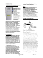
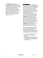
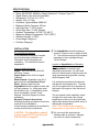
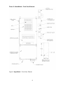
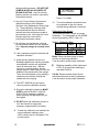
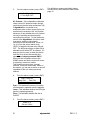
Operation Manual September 7, 2014 P/N 998-6050 Revision 1.2 TURNER DESIGNS 845 W. Maude Avenue Sunnyvale, CA 94085 Phone: (408) 749-0994 FAX: (408) 749-0998 To ensure proper system operation, Turner Designs strongly recommends reading this manual in full. After reading the entire manual, please review the following: INSTALLATION: START-UP: CALIBRATION: TROUBLESHOOTING: Prior to installation, completely review the Pre-installation/ Installation Checklist located in Appendix B. CAUTION: The AlgaeWatch should only be used with PVC plumbing kit P/N 6500-955 as supplied. Prior to start-up, completely review the Start-Up Section located on page 5. Prior to calibrating the AlgaeWatch, completely review the Calibration Procedure located on page 10. Prior to calling Turner Designs for assistance, completely review the Troubleshooting Guide located on page 22. Alarm History ............................ 18 Notes About Alarms .................. 18 Definitions ................................. 19 TABLE OF CONTENTS INTRODUCTION .................................... 1 THEORY OF OPERATION ..................... 1 Data Interpretation....................... 2 SPECIFICATIONS .................................. 3 INSTALLATION...................................... 3 Pre-Installation/Installation........... 3 Power & Utilities Required ........... 3 Required Tools & Accessories..... 3 Location & Sampling Point........... 3 Mechanical Connections ............. 4 Electrical Connections ................. 4 START-UP.............................................. 5 Start-Up Procedure...................... 5 Monitoring Mode.......................... 6 CALIBRATION ..................................... 10 Calibration Procedure................ 10 Notes on Calibrating .................. 11 Calibration Data Screen ............ 12 Table 1. Calibration Data........... 12 INTERNAL DATA LOGGER................. 13 Parameters................................ 13 Software Installation .................. 13 Running IDL Software ............... 14 Examining Downloaded Data .... 15 PREVENTATIVE MAINTENANCE ....... 16 Cleaning Basket Strainer ........... 16 Calibrating ................................. 16 Cleaning Flowcell ...................... 17 Biofouling .................................. 17 Replacement Parts.................... 17 ALARMS .............................................. 18 Alarm Delay............................... 18 Alarm Activation ........................ 18 Multiple Alarms.......................... 18 0 TROUBLESHOOTING ......................... 20 Diagnostics ............................... 20 Troubleshooting Guide .............. 22 Service Assistance/ Returned Goods........................ 24 Specifications/Accessories ................... 25 WARRANTY......................................... 26 APPENDICIES A: CONFIGURATION SHEET............... 28 B. INSTALLATION CHECKLIST ........... 29 C: FIRMWARE FUNCTIONS ................ 30 D: SCREENS FLOW CHARTS ............. 32 System Value Screens User ID Screens........................ 32 Diagnostic Screens ................... 32 Time/Date/Alarm Screens ......... 33 Data Logger Screens ................ 33 Calibration Screens................... 34 E: TROUBLESHOOTING WORKSHEET ... 35 F: FIGURES……………………………….37 G: In vivo chlorophyll concepts………… 42 FIGURES & DIAGRAMS.......................... Figure 1. Fluorescence Detection 1 Figure 2. Front View-External...... 9 Figure 3. Inlet Plumbing ............ 37 Figure 4. Outlet Plumbing.......... 38 Figure 5. Front View-Internal ..... 39 Figure 6. Front View-External.... 40 Definitions ................................. 41 algaewatch REV 1.2 parts and Figures 3 and 4, pages 36 and 37, for the plumbing diagrams). INTRODUCTION CHLOROPHYLL FLUORESCENCE AlgaeWatch is a fluorescence sensor designed to monitor the level of chlorophyll containing cells in fresh water. The AlgaeWatch continually senses the concentration of chlorophyll a, an indication of algal biomass, in the sample water. Chlorophyll a, the primary photosynthetic pigment in all plants, is a fluorescent molecule. Where chlorophyll-containing organisms are small enough, as with phytoplankton or microalgae, fluorescence may be measured directly, in vivo chlorophyll detection, without extraction or chemical treatment. For many types of qualitative work, in vivo measurement alone may answer the experimenter’s questions. For quantitative determinations, the in vivo data is calibrated by correlation with other measurements. FLUOROMETER The sample water containing algal cells is measured as a side-stream of the water passes through a polished, glass tube in the detection system. An excitation light source shines across the glass tube, the chlorophyll a in the water fluoresces, and a photodiode reads the emitted light. The quantity of light emitted is proportional to the amount of chlorophyll a present in the system (see Figure 1 below). The AlgaeWatch consists of a microprocessor-based fluorometer with electrical inputs/outputs for a flow switch, 4-20mA signal and data logging. It is engineered to ensure reliability and preassembled to simplify installation. Plumbing and calibration accessories may need to be acquired (see Replacement Parts, page 17, for a list of recommended 1 UNITS Because in vivo chlorophyll detection is a relative measurement we have not included units on the AlgaeWatch screen or in the logged data. However, if correlation between the AlgaeWatch signal and extracted chlorophyll analysis is conducted the AlgaeWatch can be calibrated to estimate actual chlorophyll concentration in micrograms/liter (µg/L) (please see Appendix G for greater detail). . THEORY OF OPERATION 90.0 ° Excitation By A Light Source Emission Read By Photodiode Water Sample Flow Figure 1. Fluorescent Detection Theory of Operation Fluorescence data can be used to supply an indication of algal growth in the sample water. Although the fluorescence data is not quantitative in nature (see Appendix G) a robust relationship between the fluorescence signal and actual chlorophyll concentration can be easily determined through a comparison with extracted chlorophyll samples. However, in many instances it may be more useful to develop a relationship between the fluorescence signal and another measure of algal growth such as cell counts or filter run times. In other cases the relative fluorescence signal may be all that is needed to make informed decisions. The power of the AlgaeWatch System is in the sensitivity of the fluorescence measurement and it’s ability to continuously monitor the algal community which is constantly changing; sometimes very rapidly. algaewatch REV 1.2 The AlgaeWatch is designed to be easily interfaced into external logging or data collection software packages. It has an analog 4-20mA signal that can deliver real-time fluorescence data to an external logging system. The system also has a 20,000-point internal data logger with user-selectable data logging intervals. Logged data can be downloaded to a PC using the RS-232 data output port (see Internal Data Logger section, pg. 13). Data Interpretation Upon installation of the AlgaeWatch, the fluorescence data should be compared to data from other systems that are affected or used to monitor algae. For example, filter run times in a water treatment facility may be negatively correlated with algal biomass. By comparing the data you will find that a filter run time may be negatively affected when the fluorescence signal reaches a specific level. Once this relationship has been determined you can set alarms on the AlgaeWatch (see Alarms, pg. 18) or through the external logging system to notify you when this level is reached. With this information you will be able to take actions to avoid decreased filter run times. Other examples of data that can be used to compare against the AlgaeWatch data include; presence of taste and odor in water, cell counts, turbidity or extracted chlorophyll data. Once relationships between chlorophyll fluorescence and other measures of interest have been established, the fluorescence data can be used to assist in decision making. Examples of how the fluorescence data can be used include: 1) Location of water intake to minimize treating water with high algal biomass. 2) Determining when to treat water for high concentrations of algae and thus minimizing the amount of treatment chemical used 2 algaewatch REV 1.2 SPECIFICATIONS Power: 90-250 VAC, 50/60 Hz, 5 amps Relay: 90-250VAC, 50/60Hz, 5 amps (fused at 3.15 amps, Type “F”) Signal Output: One 4-20 mA (isolated) Dimensions: 8” W x 4” D x 15” H Weight: 5 lbs. [2.3 kg] Enclosure: Approximates NEMA 4X Maximum Water Pressure: 100 psi • Inlet Pipe Size: ¼” NPT (male) Outlet Pipe Size: ¼” NPT (female) Ambient Temperature: 40-120°F [4°-49°C] Maximum Sample Temperature: 140°F [60°C] Relative Humidity: 0-100% Overvoltage Category II Pollution Category I INSTALLATION The AlgaeWatch should be piped as Pre-Installation/Installation A pre-installation/installation checklist provides important guidelines and information to aid in preparing for installation. The checklist is found in Appendix B. Power & Utilities Required Power: 100-130 VAC/200-250VAC, 50/60 Hz, 5 amps. Signal Output: One 4-20 mA signal (isolated) Water Sample: Supplied to unit at 0.5 gpm minimum and less than 100 psi. Drain: Sample outlet from the AlgaeWatch should be piped to drain with no back pressure, i.e., drain pipes must be below the unit. In installations where this is not feasible, contact Turner Designs Technical Support for further assistance. Required Tools and Accessories Standard plumbing and electrical tools are required for the installation. A terminal strip screwdriver is provided for making terminal strip connections. CAUTION: The AlgaeWatch should only be used with PVC plumbing kit P/N 6500-955 as supplied. 3 shown in Figures 3 and 4, pages 36 and 37. The components may be purchased separately or as a package through Turner Designs. Location of AlgaeWatch and Sampling Point The AlgaeWatch is rated for light industrial environments. Do not install within 10 feet/3 meters of devices such as large generators that generate a strong electromagnetic field. It is extremely important to eliminate air entrapment in the sample line. The best way to accomplish this is to sample from the center of the pipe or from the side of the pipe. The unit should not be installed in direct sunlight; this could cause the internal temperature of the unit to be significantly higher than ambient and produce errors or damage the components. Note: The maximum environment temperature is specified at 120oF/49oC. Do not mount this instrument on algaewatch vibrating walls or surfaces. Damage can occur to critical components. REV 1.2 Mechanical Connections Refer to Figure 6, Appendix F for the location of the required mechanical connections. Two ¼ inch NPT pipe connections are provided for ¼ inch PVC pipe hook-up. The sample outlet line is ¼ inch female; the sample inlet line is ¼ inch male shut off valve. If the Plumbing Accessory Kit is purchased, the outlet line is ¼ inch NPT (female) to connect to user-supplied ¼ inch male piping; the inlet line is ½ inch NPT (female) to connect to user-supplied ½ inch male piping (see Figures 3 and 4 on pages 36-37). IMPORTANT: Sample discharge should flow to an unrestricted drain. Pipe rises greater than 10 feet [3 m] should be avoided. To connect a wire to the terminal strip, TURN OFF MAIN POWER TO THE INSTRUMENT AT CIRCUIT BREAKER. Loosen the proper terminal screw (screwdriver provided) and insert wire from below into terminal. Tighten screw firmly. A termination legend is provided on the backside of the enclosure door for reference. To disconnect a wire, TURN OFF MAIN POWER TO THE INSTRUMENT AT CIRCUIT BREAKER. Loosen the termination screw and pull the wire out of the terminal. When finished, carefully insert the ribbon cable onto the PCB and replace enclosure face with the 4 screws. Signal wires and power wiring should NOT be run in the same conduit. Failure to separate or shield these wires will result in electrical interference. Mounting eyelets are an integral part of the plastic housing. Mounting the unit at eye level is recommended. Electrical Connections Electrical connections should be made only by trained personnel Refer to Figure 5, pg. 38 for the “Terminal Connections”, showing the terminal strip location and configuration of the required electrical connections for the power, pump, flow switch and 4-20 mA connections. To access the terminal strip, TURN OFF MAIN POWER TO THE INSTRUMENT AT CIRCUIT BREAKER, then remove the lower enclosure face (4 screws). There are two terminal strips within the instrument. #1-9 are for AC connections and A-L are for input/output connections. 4 algaewatch REV 1.2 START-UP Before start-up, the following items should be procured: Calibration Solution P/N 6500-900 (ordered/shipped separately from unit) Distilled Water Dilute Acid (not included) Plumbing Kit P/N 6500-955 (ordered/shipped separately from unit) Items listed above as ‘ordered/sent separately’ do not automatically ship with an order. Start-Up Procedure 1. 2. For future reference, a diagram of the screens is located on page 31. <0> Cal Soln Value (Calibration Solution Value)--This value relates the value of the calibration standard to a fluorescence measurement. The default value of 15 from Table 1 on page 12 is recommended, unless you are establishing a correlation to a known concentration as described in Appendix G. Before entering/changing the first System Value, the unit will prompt for the User I.D. and the screen will read Bring the sample flow to the unit. Check for leaks in the plumbing. Switch the Main Power Switch (under the enclosure face; see Figure 2, page 9) to the ON position. The LCD will illuminate. When the power is first turned on, an ID screen will appear for a few seconds, showing the firmware version and date. After 10 seconds (or press <ENT> or <HOME> for immediate access), the HOME screen will appear. The HOME screen will display the uncalibrated chlorophyll fluorescence value (3 digits). If the screen is blank, try adjusting the screen contrast using the UP and DOWN ARROWS. SAMPLE HOME SCREEN XXX AlgaeWatch During start-up, all system values should be recorded in the configuration record located in Appendix A. Entering System Values & Definitions From the HOME screen, press <0> to enter/change the first System Value; Calibration Solution Value. 5 Please input ID: Enter a valid USER ID (default is 8520) Press <ENT> Key in the Calibration Solution Value Press <ENT> Press <HOME> From the HOME screen, press <1> to enter/change the second System Value; Background Value. <1> Background Value—This value is the background fluorescence (%) for the sample. Background fluorescence can be caused by materials in the sample water that have a similar fluorescence signature to chlorophyll a. Examples of interfering compounds include dissolved organic matter, accessory algal pigments, and degraded chlorophyll (pheophytin). High concentrations of interfering compounds can result in a slight increase to the fluorescence signal. A means of compensating for this background fluorescence is to estimate the contribution of the interfering compounds to the fluorescent signal and enter the level of interference as the background value. The system will then automatically subtract the entered background level % from the algaewatch REV 1.2 fluorescent reading. The degree of background fluorescence varies from site to site. From the HOME screen, press <3> to enter/change the fourth System Value; 4 mA Output. Unit must be calibrated prior to setting the Background Value. <3> 4 mA Output—The 4-20 mA output can be connected by a signal wire to a data logger or other device to collect and store remotely from the unit. Outputs can be set to correspond to a certain range of fluorescence values. Typically the 4 mA output is set at 0. To determine the appropriate background value %, filter a sample of water through a GF/F or membrane filter to remove all algal cells. Next, inject the filtrate into the AlgaeWatch using the syringe provided. Assuming that the default calibration is active (secondary standard set to 500), take the fluorescence value of the filtrate and plug into the following formulae; Filtrate fluorescence (X) / 5 = Background Fluorescence % Press <1> Press <ENT> Key in the Background Value (%) Press <ENT> Press <HOME> From the HOME screen, press <2> to enter/change the third System Value; High Signal Alarm Level. <2> High Signal Alarm Level— If the fluorescence level rises above this level (and remains there for a 5 minute delay period), a high signal alarm will be triggered. The alarm triggers the 5V DC signal output which can be used to control external devices such as a light, siren or external control device. Please also see the section on Alarms, page 18. Press <2> Press <ENT> Key in the High Signal Alarm Level Press <ENT> Press <HOME> Initially you will most likely want to leave the High Signal Alarm disabled until you become familiar with the typical fluctuations in chlorophyll levels. Once this is established you will know recognize abnormally high signal levels and then be able to set the alarm appropriately. 6 The unit will reject as INVALID INPUT the new 4 mA value if it is not lower than the 20 mA output value. Press <3> Press <ENT> Key in the 4 mA output Press <ENT> Press <HOME> From the HOME screen, press <4> to enter/change the fifth System Value; 20 mA Output. <4> 20 mA Output—The 4-20 mA output can be connected by a signal wire to a data logger or other device to collect and store remotely from the unit. Outputs can be set to correspond to a certain range of fluorescence values. The 20 mA output should be set to a value slightly higher than the highest fluorescence signal (algal biomass) you expect to experience. If the signal exceeds the assigned 20 mA value, the unit will simply output 20mA. If the 20mA value is set excessively high you will limit the resolution of your analog data. The unit will reject as INVALID INPUT the new 20 mA value if it is not higher than the 4 mA output value. Press <4> Press <ENT> Key in the 20 mA output Press <ENT> Press <HOME> algaewatch REV 1.2 The narrower the range of the 4-20 mA settings, the greater the resolution. During an alarm condition, the 4-20 mA output will still send out the fluorescence signal. During calibration the 4-20 mA output will send out a 4-mA signal. From the HOME screen, press <5> to enter/change the sixth System Value; User ID <5> User ID Change—For security, a USER ID is required to change the System Values or calibrate the unit. The original, or default, value is 8520. To change the USER ID; Press <5> Key in Master ID (1962) Press <ENT> Key in new User ID. Press <ENT> Press <HOME> From the HOME screen, press <6> to view the seventh System Value; AC Relay Status <6> AC Relay Status—Displays the current activation status of AC Relays A and B. This screen is for visual status only, The AC Relays are used to control an external device activation state cannot be altered from the screen. Press <6> Status of AC Relays A & B Press <HOME> Setting the Real-Time Clock For future reference, record all set-up values in Appendix A. Before changing the date or time, be sure to download any data from the data logger. 7 From the HOME screen, press <> to access the date, time, and AC relay alarm values. <0> Hour—For the datalogger to reference the correct time, the hour of day must be entered. Only 1-12 numerical values will be accepted. Press <>, from HOME Press <0> Key in the hour of day (1-12) Press <ENT> Press <ESC> to return to clock menu <1> AM/PM—For the datalogger to reference the correct time (morning or evening), AM/PM must be entered. Use <ENT> to toggle between AM/PM. Press <>, from HOME Press <1> Press <ENT> to toggle between AM/PM Press <ESC> to return to clock menu <2> Minutes—For the datalogger to reference the correct time, the number of minutes after the hour must be entered. Press <>, from HOME Press <2> Key in the minutes after the hour (0-59) Press <ENT> Press <ESC> to return to clock menu <3> Month—For the datalogger to reference the correct date, the month of the year must be entered. Press <>, from HOME Press <3> Key in the month (1-12) Press <ENT> Press <ESC> to return to clock menu <4> Date—For the datalogger to reference the correct date, the day of the month must be entered. Press <>, from HOME Press <4> Key in the day (1-31) Press <ENT> Press <ESC> to return to clock menu algaewatch REV 1.2 <5> Year—For the datalogger to reference the correct date, the year must be entered. Press <>, from HOME Press <5> Key in the year (00-99) Press <ENT> Press <ESC> to return to clock menu <6> AC Cycle Time— Controls the frequency in which AC Relay Outputs are activated. Range from 10 minutes to 96 hours. Press <>, from HOME Press <6> Press <ENT> to toggle (0min – 96hrs) Press <ESC> to return to clock menu <7> AC On Time— Controls the length of time the AC Relay Outputs stay on when they are activated. Range from 0-100% of the AC Cycle Time. Press <>, from HOME Press <7> Press <ENT> to toggle (0-100%) 8 Press <ESC> to return to clock menu For Example: If you would like to use the AC Relay to control sample source using an automated valve you may want to sample raw water (containing algal cells) for 30 minutes every hour. In this case you would set the AC Cycle Time to 60minutes and the AC On Time to 50%. The result would be that the valve would allow treated municipal water to run through the system for 30 minutes every hour, thus limiting the effects of biofouling, and raw sample water would flow through the system for 30 minutes an hour. The AlgaeWatch unit start-up has now been completed. CAUTION: After start-up, wait a minimum of 15 minutes before calibrating the unit to allow the unit to come to equilibrium. algaewatch REV 1.2 Figure 2. AlgaeWatch - Front View-External Figure 2. AlgaeWatch – Front View, External 9 CALIBRATION Calibration Procedure The Calibration Procedure will take approximately 5 minutes. The cleaning procedure will take approximately 10 minutes. Refer to Figure 2 on previous page, for locations of items referred to in this procedure. For further reference, a diagram of the screens and a brief summary of the System Values can be found on page 27. Bubbles trapped in the syringe during injection of the blank or calibration standard are a possible cause of instrument error. With the syringe in a vertical position, tap the syringe against a solid object to move the bubbles to the needle end of the syringe. Then, force the bubbles out by pushing a small amount of solution through the needle end of the syringe. flowcell, and allow it to stand for 3 to 5 minutes. Next, using a clean 60 ml syringe, flush the flowcell thoroughly with 60 ml of blank solution. Syringes are provided in the Accessory and Calibration Kits. To purchase additional syringes see Replacement Parts, page 17. Step 3 Press <ENT> from the HOME screen: 1. Calib Cal Please input ID: If requested, enter valid USER ID (originally 8520) on the keypad. Step 2 Close the two-way valve flowcell shut-off valve. The valve is closed when the handle is horizontal. Blank and Dilute Acid Solutions: Both the Blank and Acid Solutions are not included with the AlgaeWatch System. Deinoized water should be used as the Blank. 10% Sulfuric Acid recommended or 1:1 HCl is acceptable if the flowcell is well rinsed. Calibration Solution: Confirm that the correct Calibration Solution is entered before beginning the Calibration Procedure by pressing <0> from the HOME screen (see Start Up Procedure for details, pg. 5). Press <ENT>: CALIBRATE SYSTEM <1> to start Step 6 Press <1>: BLANK SOLUTION Using the blank solution syringe, flush the flowcell with 60 ml of blank solution via the Luer-lock Injection Port. Then inject another 60 ml blank solution and allow it to remain in the flowcell by leaving the syringe attached. Step 7 Clean the unit by injecting the dilute acid solution (see Notes on Calibration for details, page 12) with a syringe into the flowcell. The syringe screws onto the Luer Lock fitting on the inlet of the flowcell (see Figure 2, page 9). After filling the syringe with 60 ml of dilute acid, screw the syringe onto the fitting, inject the dilute acid at a slow, steady rate into the 10 0 Days Ago Step 4 Press <1> the unit will request ID entry (unless recently entered): Step 5 Step 1 2. Data algaewatch Press <ENT>: BLANK %: XXXX REV 1.2 Any value less than 25% is acceptable. If the blank is over 25% and <0> is pressed, you will receive an error message. Press <ESC> to abort the calibration and check the blank solution. When reading is stable, press <0>. The unit will display a flashing “WAIT/wait” message in the lower right-hand corner of the screen while the unit registers the blank. Step 12 Press <1> to accept the calibration settings. The calibration is now complete. YOU MUST press <1> or the calibration will revert to the previous settings. Step 11 Open the flowcell shut-off valve. The valve is open when the handle is vertical. ** Calibration is finished ** Press <HOME> to return to the HOME Screen and normal operations. Then, the screen will display: To continue Press <ENT> Notes on Calibrating 1. Calibrate the unit when you have time to go through all the steps without interruption (approximately 10 minutes). If the keypad is not used for 15 minutes, the unit will automatically return to the HOME screen. The previous calibration will be maintained. Press <ENT>: CALIBRATION SOLUTION Using a clean syringe, flush the flowcell with 60 ml of Turner Designs calibration solution (see Replacement Parts, pg.17) via the Luer-lock Injection Port. Then inject another 60 ml calibration solution and allow it to remain in the flowcell by leaving the syringe attached. Step 9 4. The following alarms will not be monitored during calibration: Wait for the reading to stabilize. The CAL SOLUTION % should be 1-10% When the CAL SOLUTION % is stable and between 1 and 10, press <*>. The unit will display a “WAIT/wait” message in the lower right-hand corner of the screen while it registers the calibration solution. Then, the screen will display: To continue Press <ENT> 11 High Signal Alarm (“S-H”); No Sample Flow Alarm (“N-F”) 5. If an internal unit function alarm (“F-A” alarm) occurs during calibration, when you return to the HOME screen, “ALM” will be blinking in the upper left hand corner of the screen. Correct the condition causing the alarm, then recalibrate the unit. 6. During calibration, the 4-20 mA output will send out a 4-mA signal. Remove the syringe and press <ENT>: Press <1> to End Calibration 3. A request to begin calibration when an alarm is activated will be denied, unless the alarm is for: High Signal Alarm (“S-H”); Press <ENT>: CAL SOLUTION %: XX Step 10 2. The AC Relay activation schedule is not altered during calibration. 7. Use distilled or de-ionized water as blank solution. If you are not using commercial distilled water, check your source of blank solution against distilled water for algaewatch REV 1.2 background fluorescence. DO NOT USE SAMPLE WATER AS A SOURCE OF BLANK SOLUTION. Use of the wrong blanking solution can result in inaccurate fluorescence values. 8. Use only Turner Designs fluorescence calibration solution (see Calibration Solutions in the Replacement Parts, page 17). These calibration solutions meet strict specifications that are difficult to achieve when the solutions are made at the customer’s site. Not using the Turner Designs solutions could result in inaccurate fluorescence values. 9. All solutions are injected with a syringe into the stainless steel Luer-lock Injection Port. Depress plunger at a steady, slow rate. 10. Use a separate syringe for the blank and calibration solutions. 11. Avoid injecting bubbles into the unit. Bubbles trapped when injecting the blank and calibration solution are a possible cause of instrument error. With the syringe in a vertical position, tap the syringe against a solid object to move the bubbles to the needle end of the syringe. Then, force the bubbles out by pushing a small amount of solution through the needle end of the syringe. <1> Abort Cal <ESC> Continue Press <1> to abort. 16. The entire calibration procedure must be completed for the new values entered during calibration to be store Calibration Data Screen This screen provides a check on proper calibration. It is accessed from the HOME screen by pressing <ENT>, then <2>. Table 1. Calibration Data Blank Access Key Default Range Cal Std <ENT> & <2> 0.0 15.0 0-250 0-1,000 Blank: Shows raw data output for blank solution as set during calibration. It can be used to check proper calibration. Blanking capability of the instrument is 25% (e.g. maximum blanking of raw data is 250.0) Cal Std: Shows raw data output for the standard solution as set during calibration. It can be used to check proper calibration. 12. The LEFT ARROW may be used to return to previous calibration screens. 13. During the calibration sequence, MAKE SURE to wait for BLANK % and CAL SOLUTION % readings to stabilize before pressing the appropriate key on the keypad. 14. DO NOT allow the calibration solution to sit in the flowcell for longer than necessary (approximately 2 minutes). 15. To abort the calibration and maintain the current calibration settings, press <ESC> before step 9 is completed. The unit will prompt 12 algaewatch REV 1.2 INTERNAL DATA LOGGER AlgaeWatch is equipped with an internal data logger to record the unit’s output. Data is saved in a compressed binary (BIN) format to be downloaded and converted to ASCII data with the Internal Data Logger (IDL) software. Data Logger Parameters The unit’s data logger is accessed from the HOME screen by pressing the data disk <> symbol on the keypad. From the data logger menu, you can turn the data logger on/off, set the interval, and download and erase data. 1. The clock is important to the data logging functions. Once the date and time are set and data has been logged, download the current data before changing the date or time or you may corrupt or erase your data. From the HOME screen, press <> to see the data logger menu. Before entering/changing the data logger, the unit will prompt for the User I.D. (Default=8520) and the screen will read: Download current data before changing the data-logging interval or you may corrupt your data. 4. To download the data to a Windows based PC or to erase data, from the data logger menu, press <2> or <3>, respectively. Installing the Internal Data Logger Software The Internal Data Logger (IDL) software is designed to interface from the AlgaeWatch to a Windows 95-2000 based PC. The IDL program is used to download the compressed data from the AlgaeWatch and convert it to an ASCII format for use with a spreadsheet or other program. To install the IDL software: 1. Insert the IDL disk into your computer. 2. Access “Run” from Windows. Type: a:\setup. (Be sure to enter the correct drive for the disk. Running the Internal Data Logger Software Please input ID: To download data from the AlgaeWatch: After entering the User ID the screen will read: Datalogger: <0> - <3> 2. To log data or stop logging data, press <0>: Status: Stop <ENT> to toggle Press <ENT> to toggle from Stop to Logging. Press <ESC> to return to the main Datalogger screen. 3. To set the data logging interval press <1>. Press <ENT> to toggle from 1, 2, 3, 5, 10, 20, or 30 minutes, or 1 second. 1. Using the cable provided, connect your computer to the unit’s serial port (phone jack style connector). (See Figure 2, page 9 to locate.) 2. Load the IDL program on the PC by clicking twice on the IDL.exe icon. The IDL Main Menu will appear. 3. Click on Serial Port Setup to select the appropriate port (1, 2, or 3) for your PC. 4. Click on Download Data from Instrument to File to display the downloading box on the PC. Interval: 1 min <ENT> to toggle 13 algaewatch REV 1.2 You may download and convert to an ASCII file in a single process by clicking on Download and Convert Data from Instrument to File. In this case, IDL will prompt you for downloading, then conversion in a single process incorporating steps 5 - 10. 8. If you would like to wait until later to convert the data to ASCII format in order to save disk space, then skip to step 12. To convert the data to an ASCII file now, go on to step 9. 5. From the AlgaeWatch, set the data logger to Stop, by pressing <> from the HOME screen, then <0>, then <ENT> to toggle. 6. From the AlgaeWatch, access the downloading screen by pressing <2> from the data logger main menu: Download data: 5x <8> to start 7. On the AlgaeWatch, press <8> five times to start downloading data. The PC will display a bar graph and data block countdown. The AlgaeWatch will display: Download data: Data Blks: XX If there is an error in downloading data, the following screen will be displayed: Comm error !!! <ESC> to retry a. If the error screen appears, press <ESC> and make sure the serial cable is securely connected and operational. b. Make sure the correct serial port has been selected (IDL software main menu). c. Check to make sure that the AlgaeWatch date and time functions have not been changed for the current data logged. 9. To convert a BIN file to a regular ASCII file (PRN file), from the PC click on the Convert Downloaded Data File to ASCII File. IDL will then ask you what file you would like to convert to ASCII. Click on Browse to locate the file or click on OK to accept the default file. 10. Click on OK to begin conversion. IDL will display “Conversion has started.” IDL will convert the BIN file to an ASCII file of the same name with the extension “PRN”. When “Conversion completed” appears, click on OK to return to IDL Main Menu. 11. To exit IDL, click on the “X” in the upper right-hand corner of the software window or select “Exit” from the file menu. 12. Disconnect the computer from the unit. Erase the data currently in the AlgaeWatch by pressing <> from the HOME screen, then <3> from the data logger menu: Erase data: <9> 5X to start When data is erased, the unit will display: d. Verify that you completed steps 1 7. Correct screens must be displayed on both the computer and AlgaeWatch. 14 When downloading is finished, IDL will ask you to name the file and select the path (folder) for the downloaded file. Click on Browse to change the name or path; or you can accept the default name (test.bin) and path. Then, click on OK to return to the Main Menu. algaewatch Erase data: All Data Erased REV 1.2 13. Enter new internal data logging parameters on the AlgaeWatch if desired, or resume logging with the previous parameters. 14. Return the unit to normal operation. Examining the Downloaded Data The ASCII-format “PRN” files can be opened, viewed, or printed using most standard computer programs. To examine the data, run your program, then open or import the “PRN” file containing the downloaded data. A typical line of data from the internal data logger will look like this (your numbers will vary): 00001: 10/24/91 14:10:28 Index Date Time 15 = 11.300 Sample Reading algaewatch REV 1.2 PREVENTATIVE MAINTENANCE Proper preventative maintenance is critical to the success of the AlgaeWatch System. Once the unit is installed, started-up, and calibrated, the initial settings should not require change. Refer to Start-up, page 5, of this manual for instructions. Any start-up or shutdown must be made using the AlgaeWatch Main Power Switch (see Figure 2, page 9). The System Values are retained in battery back-up memory for up to five years. However, the Start-up procedure should be followed to ensure fluorometer calibration and alarm settings are correct if the unit has been disconnected for any length of time. This unit has been assembled with a new desiccant plug to ensure the area surrounding the flowcell is free of any moisture. As this plug absorbs condensate, it will change from a light blue to light pink at the saturation point and should be replaced promptly. The unit can remain in operation during this replacement. Readings should be monitored during this replacement time as small variances might occur. Refer to the Replacement Parts section, pg. 17, for replacement plugs ordering information. The following preventative maintenance should be performed to ensure optimum operation and maximum life. Cleaning the Basket Strainer The basket strainer screen should be cleaned as needed as follows: 1) Shut off the inlet valve to the basket strainer; 2) Remove the screen by unscrewing the clear plastic basket housing and clean the screen; 3) Replace the screen; 4) Open the inlet valve to the basket strainer. 5) Wait for the unit to equilibrate and air to purge from the unit. Calibrating Calibration should be checked regularly. Typically, calibration should be checked using the secondary standard included in 16 the calibration kit every two to three weeks. Cleaning the Flowcell How often the flowcell should be cleaned depends on the quality of the water being monitored. The flowcell is unlikely to clog, but occasionally residue or biofilms can build up on the inside of the glass cuvette. A fouled or discolored flowcell can result in low or erratic readings. Initially, routine flowcell cleaning should be conducted and fluorescence readings before and after cleaning should carefully noted. If a significant change in the reading resulted from cleaning, a shorter cleaning interval should be implemented. If there was no significant change in the reading after cleaning, a longer cleaning interval can be used. For routine cleaning, follow steps 1 and 2 in the Calibration Procedure, page 10; open the flowcell shut-off valve when cleaning completed. For cleaning the flowcell with a brush, perform the following steps (refer to Figure 2, pg. 9): 1. Turn OFF the Main Power Switch. 2. Shut off the flow to the flowcell. Flow is off when valve handle below the flowcell is horizontal. It is recommended that the inlet valve be closed and the 3-way outlet valve also be closed (the outlet valve is then open to the atmosphere; see Figures 4 and 5, pages 37-38). 3. CAUTION: After injecting acid solution into the flowcell via the luer lock port, be sure to flush it out completely BEFORE removing the clean-out cap. 4. Remove the clean-out cap and open the clean out valve (horizontal position). Dip the flowcell brush into the dilute acid solution and insert it gently into the cleanout opening. 5. Slide it gently up and down in the opening to remove any coating on the glass cuvette. algaewatch REV 1.2 6. Close the clean-out valve (vertical position) and replace the flowcell clean-out cap. 7. Turn on the flow. Flow is ON when the valve handle is vertical. 8. Turn ON the Main Power Switch. 9. Calibrate the unit after allowing it to warm up for 15 minutes (refer to Calibration Procedure, page 10). Replacement Parts: 6500-900 Calibration Kit 6000-970 Desiccant Plugs (Pkg. 3) 6000-350 Flowcell Brush (Pkg. 3) 6000-119 Data Cable 6000-910 Syringes (Pkg. 10) 120-0110 Flow Switch 119-0103 Basket Strainer Biofouling Sample water containing bacterial and algal cells will be in contact with the glass flowcell of the AlgaeWatch System. Because of this a biofilm will gradually begin to grow on the flowcell and at some point the film will become thick enough to interfere with the fluorescent readings. The rate of fouling will change from site to site. The AlgaeWatch has an optical compensation system that will correct for fouling to a certain point. Beyond this it is the user’s responsibility to clean the flowcell on a regular basis to prevent corruption of the data. There are several ways in which the rate of biofouling can be slowed. 1) Flow rate: As the flow rate in the flowcell increases the rate to which biofouling organisms and attach and grow on the flowcell walls will decrease. The minimum flow rate required is 0.5 gpm. Flow rates in the range of 2-5 gpm could significantly decrease flowcell fouling rates. 2) Flowcell cleaning: The AlgaeWatch has been designed to allow quick and easy cleaning of the flowcell. A regular schedule should be established in order to prevent the establishment of biofouling organisms on the flowcell. . 17 algaewatch REV 1.2 ALARMS Alarms have been built into the unit to warn about conditions relating to high algal levels and internal instrument functions. There are two types of alarms for AlgaeWatch: 1. System function alarms, Fluorometer (lamp) and No Flow (“F-A” and “N-F” alarms). See Table 2. 2. High Signal alarms. See Table 3, page 19. Alarm History The alarm history can be viewed, by pressing <> (LEFT ARROW) from the HOME screen. This shows which alarms have been activated since the alarm history screen was last cleared. To clear this screen, press <*> five times while the alarm history screen is displayed; “No alarm since last reset” will be displayed. Notes About Alarms 1. Refer to Table 5, page 25, for default values. 2. Alarm Delay To avoid unnecessary triggering of alarms, the condition must be in effect for a certain delay period. See Tables 2 and 3. 3. Alarm Activation When an alarm is triggered, “ALM” will blink in the upper left hand corner of the HOME screen. From any other screen, when the alarm is first activated, the unit will return to the HOME screen, display the “ALM” message in the upper left hand corner. Pressing the <ESC> key will display the current alarm. Take the appropriate action to clear the condition (see Troubleshooting, page 20). When the condition triggering the alarm is cured, “ALM” will disappear from the HOME screen. Alarms cannot be aborted without curing the problem. No alarms are monitored when the unit is turned OFF. Certain alarms are not monitored during calibration (see Notes on Calibrating, page 11). When the unit is first powered up, the HIGH SIGNAL alarm will begin to be monitored 5 minutes after start up. Thus, a problem or spike during startup will not mistrigger the HIGH SIGNAL ALARM. All alarms will be reset automatically if the alarm condition is corrected. During an alarm condition, the 4-20 mA will still send out the fluorescence signal. 4. 5. Table 2. System Function Alarms Alarm Lamp (F-A) No Sample Flow (N-F) Delay (min.) Alarm Condition Normal 1 OFF ON 5 OFF ON Multiple Alarms If multiple alarms are triggered, alarms will be listed on the alarm screen when <ESC> is pressed from the HOME screen. (Note: alarms are not listed in the order they occur.) For example, the alarm screen might display: N-F 18 F-A algaewatch REV 1.2 System Function Alarm Definitions a. Lamp (F-A)--Indicates the status of the excitation light source. Reports whether the lamp is OFF or ON. If the power is ON and the lamp is good, the diagnostic screen will display “Lamp: ON”. b. No Sample Flow (N-F)--If there is a problem with the sample flow lasting for the 10 minute delay period, a “N-F” alarm will be noted. The flow switch used is rated at 0.5 gpm minimum flow (tolerance is 0.4 0.6 gpm). High Signal (S-H)--If the fluorescence signal rises above the user-set level (see Table 5, page 24), and remains there for the 2 minute delay period, a “S-H” alarm will be noted. If there is a “S-H” alarm, check if the High Signal Alarm Level is set too low. Verify that calibration has been performed properly. If there is a “N-F” alarm, check terminal connections to the flow switch. Check the sample feed lines and the unit’s flowcell for any restriction. Electrical connections should be performed only by trained personnel. To determine which alarm is currently active, press <ESC> from the HOME screen and the alarm status screen will appear. F-A N-F You may also view the lamp and flow status in real-time by accessing the diagnostic screens. The diagnostic screens are accessed by pressing <*> from the HOME screen and then <ENT>. (See Diagnostic Screen flowchart, pg. 31) If the Lamp displays “OFF” and there is power to the unit, contact the Turner Designs Technical Support. Table 3. High Signal Alarms Alarm High Signal (S-H) 19 Delay (min.) 2 Range Default 0.2-999 999 algaewatch REV 1.2 page 11) to determine whether the last calibration seems correct. TROUBLESHOOTING Introduction Because the AlgaeWatch system includes hardware, software, and chemistry, it is important to collect all the diagnostic data first. To facilitate data collection, each AlgaeWatch unit is shipped with the Troubleshooting Worksheet ( E). After collecting the data requested by the worksheet most problems can be solved over the phone with the assistance of Turner Designs Technical Services (see Service Assistance/Returned Goods, page 24, for contact information). When using this guide, it is assumed that all problems associated with an alarm have been resolved first. Something as simple as a clogged basket strainer can lead to other alarm messages, which could all be solved at one time simply by cleaning basket strainer. Generally speaking, if there is no System Function Alarm (“F-A” alarm), this is persuasive evidence that the electronics of the instrument are functioning properly. In that case, it is likely that any problem is either mechanical, or has resulted from another system problem, or from the operator’s unfamiliarity with the unit. The troubleshooting procedure works best in this sequence: 1. Handle any alarms (see Alarms, page 17). 2. Determine whether or not the System Values have been entered correctly (see recorded values in Appendix A and the System Default Values in Table 5, page 24). 3. Perform the Diagnostics procedure as described on the following page. 4. Determine whether or not the chemistry is behaving as expected. Does the blank read close to zero on the HOME screen and calibration solution read between 1-5% on the calibration screen? Check the “Cal data” screen (see Calibration Data Screen, 20 5. Complete the Troubleshooting Worksheet, Appendix E. 6. Contact the Turner Designs Technical Support (see Service Assistance/Returned Goods, page 24). Diagnostics AlgaeWatch contains diagnostic screens and functions to aid in troubleshooting. These functions are accessed from the HOME screen by pressing <*>, then <ENT> to page through the series of 4 screens. Press the <LEFT ARROW> to return to a previous screen, or <ESC> or <HOME> to return to the HOME screen. 1. From the HOME screen, press <*> TURNER DESIGNS 6500XBL 1.0 0302 This screen displays the version number and release date of the firmware installed in the instrument. 2. From the above screen, press <ENT> Raw: XXX FS% XX Raw—The “raw” signal output is the output from the unit’s light detector. This is the output AlgaeWatch uses (in conjunction with the Cal Soln Value, Background value, etc.) to arrive at the fluorescence readout on the HOME screen. It can be used to diagnose problems with the unit. For example, if the HOME screen always reads zero, and the Raw reading is also zero, there may be an optics problem. If the HOME screen reads zero but the Raw reading does not read zero, then check the Cal Soln Value to make sure the proper value is entered. FS%--Acts like an analog meter. Indicates the raw signal output as a percentage of the maximum that can be read. Value Range RAW 0.00 to 1000.00 (reading >1000.00 will display “OVER”) FS% 0 to 100 (if Blank equals 0) algaewatch REV 1.2 3. From the above screen, press <ENT> For definitions, ranges, and default values of these items, see Calibration Data Screen, page 12. 1: Test RlyA: ON 2: Test RlyB: OFF AC Outputs—Two independent solid state relays control AC electrical output through connections (terminal strip connections 4-9) If AlgaeWatch is connected to an automated valve or other control device via terminal strip connections 4-9, this function allows you to test whether the unit’s internal circuitry is operating and terminal strip connections are correct. To test the device control of the AlgaeWatch, the device itself must be on, working, and properly connected to the terminal strip. Press <1> (or <2>) from the screen above, then <ENT> to toggle the chosen relay ON and OFF. The device should go on when ON is selected and off when OFF is selected. If it does not, then be sure to check the device itself first, then check the terminal strip connections (trained personnel ONLY). When the test is finished, return to the HOME screen and device control will revert to control by current unit values. This function can serve as a “manual override” for device control tests. While on this screen, you can turn a device on and off regardless of the unit values previously entered. 4. From the above screen, press <ENT> Oper: XXXX Hrs Lamp ON Flow: ON Oper—This indicates how many hours the unit has been in operation since installation. Lamp—This indicates whether the LED light source is operating properly. Flow—This indicates whether the flow is ON/OFF. 5. From the above screen, press <ENT>: Blank: X.X Cal std: XXX.X 21 algaewatch REV 1.2 Troubleshooting Guide REMEMBER, handle any alarms FIRST. SYMPTOM POSSIBLE CAUSE SOLUTION HOME screen displays over/OVER (blinking from over to OVER). 1. System Values are incorrect (i.e. Cal Soln Value, etc.). 1. Check the Configuration Record for the site. Access the System Values and verify that they are entered correctly. 2. Incorrect calibration 1. Check the Calibration Data screen. Recalibrate the unit; be sure to use the correct calibration solution and that the reading is between 1% - 10%. Check the expiration date of the solution. 1. Possible optics problem. Improper or deteriorated filters. Check the FS% reading in the Diagnostics sequence. A blinking ‘over/OVER’ is a different symptom than a steady ‘OVER’ and indicates that the sample reading exceeds 999. This is most likely related to the System Values entered for the site. If, for example, a Cal Soln Value of 200 was erroneously entered, the unit’s numerical calculation of the sample reading might exceed 999. (NOTE: Examine “Possible Cause”/”Solution” in the numbered order.) HOME screen displays OVER (not blinking from over to OVER). A steady ‘OVER’ is a different symptom than a blinking ‘over/OVER’ and indicates that the sample reading is too high for the unit’s light detector. This is related to the chemistry of the sample and displays that the sample readings are too high for the unit at the current sensitivity level. (NOTE: Examine the “Possible Cause”/”Solution” in the numbered order.) 22 SYMPTOM POSSIBLE CAUSE 2. Incorrect calibration. 3. System Values are incorrect (i.e. Cal Soln Value, etc.). HOME screen displays minus sign (negative readings), i.e., sample is reading less concentrated than blank as set during last calibration. SOLUTION Recalibrate the unit, making sure that you are using the correct Calibration Solution, and that it reads between 1 and 10%. Check the expiration date of the solution. Check the Configuration Record. Access the System Values and verify they are entered correctly. 1. Fouled flowcell. Thoroughly clean and rinse flowcell with recommended solution, using the brush if necessary. (See Cleaning the Flowcell, page 16.) 2. Calibrated with contaminated blanking solution, or the calibration solution was used instead of the blank solution. Recalibrate. HOME screen reads zero. System Values incorrectly set. Make sure valid System Values entered (see Appendix A). Screen blank or black. LCD’s screen contrast too high or too low Unit does not calibrate. Failure to complete entire calibration procedure. AC Out is not operating properly. 1. Problem with terminal strip connections; or device itself. If screen is blank, adjust contrast by pressing UP ARROW (if screen is black, use the DOWN ARROW) continuously until screen is visible. Use UP and DOWN arrows to fine adjust. You must press <1> at the end of the calibration sequence for the unit to accept the values. Recalibrate. If there is an alarm, check the High Signal Alarm for 0-5V signal problems. Refer to Diagnostics (page 20), AC Out test function, to test if the unit is properly controlling the device using the AC Relays. Make sure the device itself is powered on and operational. Replace fuse with spare fuse located in the spare fuse holder on the PCB. 2. Fuse has ‘blown’. 23 AlgaeWatch REV 1.2 SYMPTOM POSSIBLE CAUSE SOLUTION Background value ineffective (i.e. HOME screen reading does not change when the Background value is changed). This is not usually cause for alarm as the HOME screen reading is a result of a combination of factors. Do not attempt to change current settings unless you are certain something is wrong. Consult with the Turner Designs Technical Services. Unit does not respond to calibration solutions. System Values incorrectly entered. Check that the correct Background Test Value and Cal Soln Value have been entered (see Appendix A). SERVICE ASSISTANCE/RETURNED GOODS Turner Designs’ experienced technical staff is available to assist you in troubleshooting the AlgaeWatch unit. However, should you need to return anything for the unit, a Returned Materials Authorization (RMA) must be obtained from Turner Designs. Please call prior to returning any equipment. The use of an RMA minimizes the potential for administrative delays and facilitates prompt turn-around. Turner Designs Technical Support Telephone: 877-316-8049 (Outside U.S. 408-749-0994) FAX: 408-749-0998 E-mail: [email protected] Hours: 8:30 a.m. – 5:00 p.m., Pacific Time 24 AlgaeWatch REV 1.2 SPECIFICATIONS AND ACCESSORIES Specifications Power: 90-250 VAC/200-250 VAC, 50/60 Hz, 5 amps Relays: 90-250 VAC/200-250 VAC, 50/60 Hz, 5 amps (fused at 3.15 amps ea. Type “F”) Signal output: One 4-20 mA, isolated Dimensions: 8” W x 4” D x 15” H; 20cm x 10cm x 38cm Weight: 5 lbs; 2.3 kg Enclosure: Approximates NEMA 4X Sample Flow: Maximum Water Pressure: 100 psi Plumbing: Inlet Pipe Size: Outlet Pipe Size: ¼” NPT (Male) ¼” NPT (Female) Environment: Ambient Temperature: Maximum sample temperature: Relative Humidity: 40°F to 120°F; 4°C to 49°C 140°F; 60°C 0-100% Table 5. System Default Values and Ranges 25 SYSTEM VALUE ACCESS KEY DEFAULT VALUE RANGE Cal Soln Value <0> 15.00 0.000 to 998.000 Background Value <1> 0.0% 0.0 to 100.0 High Signal Alarm Level <2> 999.000 (PPM) 0.004 to 999.000 4 mA Output <3> 0.000 0.000 to 998.000 20 mA Output <4> 100.00 0.002 to 999.000 Software Version <*> N/A Fixed Master ID <5> 7420 Fixed User ID <5> 8520 0 TO 9999 AC Cycle Time <clock>, <6> OFF 1 to 168 hours AC On Time <clock>, <7> OFF 1 to 1440 min. AlgaeWatch REV 1.2 Accessories Included with Unit Flowcell brush Terminal strip tool Operating manual 2 spare clean-out port caps Datalogger cable Datalogger disk Spare desiccant plugs Suggested Optional Accessories Calibration Kit (P/N 6500-900): Kit includes Calibration Standard (1L), syringes, flowcell brushes Plumbing Kit (6500-955): includes inlet and outlet plumbing kits Warranty Terms Turner Designs warrants the AlgaeWatch and accessories to be free from defects in materials and workmanship under normal use and service for a period of 12 months from the date of shipment from Turner Designs with the following restrictions: • Turner Designs is not responsible for replacing parts damaged by accident or neglect. Your instrument must be installed according to instructions in the User’s Manual. Damage from corrosion is not covered. Damage caused by customer modification of the instrument is not covered. • This warranty covers only Turner Designs products and is not extended to equipment used with our products. We are not responsible for incidental or consequential damages, except in those states where this limitation is not allowed. This warranty gives you specific legal rights and you may have other rights which vary from state to state. • Damage incurred in shipping is not covered. Warranty Service To obtain service during the warranty period, the owner shall take the following steps: 1. Write, email or call the Turner Designs Technical Support department and describe as precisely as possible the nature of the problem. Phone: 1 (877) 316-8049 Email: [email protected] 2. Carry out any adjustments or tests as suggested by the Technical Support Department. 3. If proper performance is not obtained you will be issued a Return Materials Authorization number (RMA) to reference. Package the unit, write the RMA number on the outside of the shipping carton, and ship the instrument, prepaid, to Turner Designs. If the failure is covered under the warranty terms, the instrument will be repaired and returned free of charge, for all customers in the contiguous continental United States. 26 AlgaeWatch REV 1.2 For customers outside of the contiguous continental United States who purchased equipment from one of our authorized distributors, contact the distributor. If you purchased directly, contact us. We will repair the instrument at no charge. Customer pays for shipping duties and documentation to Turner Designs. Turner Designs pays for return shipment (custom duties, taxes and fees are the responsibility of the customer). Out-of-Warranty Service Follow steps for Warranty Service as listed above. If our Technical Support department can assist you by phone or correspondence, we will be glad to, at no charge. Repair service will be billed on a fixed price basis, plus any applicable duties and/or taxes. Shipment to Turner Designs should be prepaid. Your bill will include return shipment freight charges. Address for Shipment: Turner Designs, Inc. 845 W. Maude Ave. Sunnyvale, CA 94085 27 AlgaeWatch REV 1.2 APPENDIX A CONFIGURATION RECORD Date Configured: _____ Technician: _____ Serial Number:_______ System Value Range Background Value 0.0 to 100.0 % Cal. Solution Value 0.000 to 998.000 High Signal Alarm Setpoint 0.004 to 999.000 4mA Output 0.000 to 998.000 20mA Output 0.002 to 999.000 AC Cycle Time 10min - 96hours AC On Time 1 to 100% of AC Cycle Time User ID 4 digit 28 AlgaeWatch Configuration REV 1.2 APPENDIX B Pre-Installation/Installation Checklist The following checklist is provided so the appropriate preparations may be made prior to equipment start-up. Completion of the listed items is mandatory to assure proper installation and a properly-functioning piece of equipment. 1. ________ ________ 2. ________ ________ 3. ________ ________ Check sample water background fluorescence (Background lab test code). Check that the turbidity is less than 150 NTU. Assure water temperatures of 32-140oF. INSTALLATION REQUIREMENTS - CUSTOMER 1. ________ ________ Locate the unit within 125 feet from the sample point. 2. ________ ________ Locate the unit out of direct sunlight. 3. ________ ________ Locate the unit where ambient temperatures are 40-120°F/4-49°C. 4. ________ ________ Locate the unit at least 10 feet/3 meters from devices such as large generators, which require a great deal of electrical power, or generate a strong electromagnetic field. CUSTOMER REQUIREMENTS - PLUMBER 1. ________ ________ The sample stream must be plumbed to the unit to deliver at a rate >0.5 gpm (between 0.5 and 1.25 gpm is optimal) and <100 psi. One ½-inch and one ¼-inch NPT pipe connections (both female) are provided for PVC pipe hook-up (refer to Figure 3 and 4, page 3637). Ensure that sampling point will avoid air entrapment. 2. ________ ________ Sample from the side of the water line to avoid air entrapment. 3. ________ ________ Provide a free, unrestricted drain for the sample stream, preferably to the tower basin (no back pressure, max. 10 ft/3 m rise). CUSTOMER REQUIREMENTS - ELECTRICIAN 1. ________ ________ Ensure that the environment will support a NEMA 4X-type enclosure. 2. ________ ________ Provide 90-250 VAC, 50/60 Hz, 5 amp electrical service to the AlgaeWatch. 3. ________ ________ If the unit’s 4-20 mA output signal will be used, check to see if an isolator should be purchased. 4. ________ ________ Terminate flow switch wiring on terminal strip (refer to Figure 5, pg. 38). FINAL REQUIREMENTS - CUSTOMER 1. ________ ________ Obtain needed materials (calibration solution, distilled water, dilute acid, calibration kit, flowcell cleaning brushes) Customer’s Responsibilities: This checklist outlines the work that is required prior to start-up. Work is necessary to ensure quality and proper operation. However, if any of these requirements cannot be met, contact Turner Designs Technical Services. In some cases, alternative procedures will still provide reliable results. 29 AlgaeWatch REV 1.2 APPENDIX C FIRMWARE FUNCTIONS The unit has a software interface that simplifies calibration and changes of unit values (See Screens Flow Charts, pages 31-33). The following descriptions of the unit’s software functions will help provide a better understanding of the unit: 1. Screens—Built into the unit are a series of computerized screens, which are called up using the keypad and shown on the digital display. 1.1 Home Screen—Once the unit has been activated, the HOME screen is continuously displayed, except when accessing other screens. From the HOME screen, access the calibration data and the calibration sequence by pressing <ENT>. Other screens are accessed from the HOME screen by pressing various keys on the keypad. Go to the HOME screen by pressing the <HOME> key, except during the calibration procedure. To return to the HOME screen from calibration, first press <ESC> to abort the calibration sequence. 1.2 Warning Screens—There are warning screens throughout the software that inform of invalid entries (for values or ID). 1.3 Alarms—When an alarm occurs, “ALM” blinks in the upper left hand corner of the HOME screen. The nature of the alarm can be discovered by pressing <ESC> from the HOME screen (see Alarms, page 17, and Troubleshooting, page 19). 2. Keypad Functions 2.1 Left Arrow—The LEFT ARROW can be used to correct typing errors when data is being entered or changed. It acts as a backspace or delete key. During calibration, it can be used to return to previous screens in the sequence if you wish to re-run the calibration. It is also used from the HOME screen to view the alarm history. 2.2 Up and Down Arrows—From HOME screen, can be used to change screen contrast. 2.3 Escape and Enter—You can escape to the previous screen or abort the calibration sequence by pressing the <ESC> key. While viewing a System Value, press <ENT> to access the screen to change that value. After entering a new System Value, press <ENT> to accept the new value. 3. User Identification—To change System Values or to calibrate the instrument, a four-digit USER ID is required. For security, a MASTER ID, different from the USER ID, is required to view or change the USER ID. 30 AlgaeWatch REV 1.2 Once an ID has been entered, if the keypad is not used for 15 minutes, the unit will automatically return to the HOME screen. The ID will have to be entered again before the unit values can be changed or calibration can be performed. 4. Fluorescence Display—After the unit is powered-up or after calibration, the fluorescence displayed will not react immediately, but will respond after a delay of about 10 seconds. 5. LCD Contrast—The contrast of the Liquid Crystal Display can be adjusted on any screen (except during calibration) by pressing the UP and DOWN ARROWS. 31 AlgaeWatch REV 1.2 APPENDIX D Screens Flow Chart Systems Values. From the HOME screen, press key to view value. To change value, press <ENT> while viewing, input ID, enter new value, and press <ENT> again. Press HOME screen. XXX AlgaeWatch HOME Home Screen shows fluorescence signal and whether data logger and alarms are active. Cal Soln value: XXX.XXX Relates the value of the tracer standard to a fluorescence measurement. 1 Background Value XX.X Background fluorescence for system. 2 High Sig Alarm: XXX.XXX Set the fluorescence value that once exceeded will set the High Signal Alarm 4mA output: XXX.XXX Output can be set to correspond to a certain fluorescence signal. 0 3 4 ← ESC 32 20mA output: XXX.XXX S-H N-F N-F View alarms triggered since last reset. To view or change User ID, Master ID is required: Input MASTER ID: 5 ENT XXXX New: Diagnostic Screens. To access unit's diagnostic screens, from HOME press: Θ TURNER DESIGNS 6500XBL 1.0 0302 ENT Raw: XXX.XX FS%: XX ENT 1: Test RlyA: ON 2: Test RlyB: OFF ENT Oper: XXX Hrs Lamp ON Flow ON ENT 1: 4mA XXX 2: 20mA XXXX ENT Blank: Cal std: If alarm is triggered, shows which alarm(s). AlgaeWatch User ID: XXXX XX.X XXX.X REV 1.2 Screens Flow Chart (Con’t) From the HOME screen, press <>, <>, or <*>to access the following functions. For example, to change the clock settings or alarm functions, first press <>, then the number of the function to be changed. Key in the new value and press <ENT>, then <ESC> to return to the clock menu. Time*, Date*, & Alarm Screens Datalogger Screens <0> to 02/21/99 <7> 07:58:30AM 0 Hour: New: 1 AM/PM: PM <ENT> to toggle 2 Min: New: 7 2 Date: New: 0 5 Year: New: 02 6 AC Cycle Time: Off <ENT> to toggle 4 7 Datalogger: <0> - <3> 0 Status: Stop <ENT> to toggle 1 *Interval: 1min <ENT> to toggle 2 Download data: 5x <8> to start 3 Erase data: 5x <9> to start 0 Month: New: 3 *Download data logger before changing! Changing Calibration Solution Value From the HOME screen: AC Limit Time:0% <ENT> to toggle 0 Cal Solu Value 100 ENT Please input ID: XXXX ENT 100 New: 20 ESC 33 AlgaeWatch REV 1.2 Screens Flow Chart (Con’t): Calibration Screens Clean the flowcell before calibrating. Press Key HOME ENT See Screen XXX AlgaeWatch 1. Calib 2. Data Cal XX Days Ago 1. From the HOME screen, press <ENT>. 2. Press <2> to view raw data output for blank and standard as set during current calibration, OR, press <1> to begin calibration sequence. 2 Blank: XX.X Cal std: XXX.X 1 Please input ID: 3. If requested, key in ID and press <ENT>. If not requested, go to step 4. CALIBRATE SYSTEM <1> To Start 4. Press <1> to begin. 1 BLANK SOLUTION ENT BLANK %: XX 5. Close the valve to stop sample flow by moving lever to the horizontal position. Inject 120 ml of blank solution (flush with 60 ml, then allow portion of second 60 ml to remain in flowcell). Press <ENT>. 6. If the number shown is less than 25, wait for number to stabilize, then press <0>. 0 BLANK %: XX ENT wait 7. After WAIT command disappears, unit will prompt you to press <ENT> to continue. To continue Press <ENT> 8. Press <ENT>. ENT CALIBRATION SOLUTION ENT CAL SOLUTION %: XX * CAL SOLUTION %: XX wait 9. Inject 120 ml of calibration solution (flush with 60 ml, then allow portion of second 60 ml to remain in flowcell). Press <ENT>. 10. If the number shown is between 1 and 10, wait for reading to stabilize, then press <*>. WAIT command will appear. 11. When finished, unit will prompt you to press <ENT> to continue. ENT 34 To continue Press <ENT> 12. Press <ENT>. Press <1> to End Calibration 13. Press <1> to accept the new calibration settings. Unit returns to calibration menu. Open valve to start sample flow by returning lever to the vertical position. Calibration is finished. AlgaeWatch REV 1.2 APPENDIX E AlgaeWatch TROUBLESHOOTING WORKSHEET The Troubleshooting Worksheet is designed to facilitate diagnostic data collection. After collecting all data on the worksheet, most problems can be solved over the telephone. Refer to the Service Assistance/Returned Goods Section for the appropriate numbers. Please fill out worksheet completely—All entries are important GENERAL INFORMATION: Unit Serial No.: (Tag is located beneath sample block.) Field Contact Name: Field Contact Phone: Description of Symptoms: Date/Time Symptoms Started: Describe Any Physical Damage To Unit: Date Of Last Calibration: (Press <ENT> from HOME screen to read last calibration date.) THE HOME SCREEN READS: RFU If “ALM” is blinking, press <ESC> and record alarms PHYSICAL INSPECTION: 1. Is main power switch on? 2. Can LCD contrast be adjusted using the UP/DOWN arrows? YES NO YES NO With Acid: With Brush: 4. Turn main power to the instrument off and remove enclosure face being careful to remove keypad ribbon cable from the circuit board. Tug each wire to the terminal strip to see if it is firmly connected. 3. Date flowcell was last cleaned: 35 AlgaeWatch REV 1.2 [AlgaeWatch TROUBLESHOOTING WORKSHEET] AlgaeWatch RECORD SYSTEM VALUES ACCESS KEYS SYSTEM VALUE <HOME> <0> Cal Soln Value <HOME> <1> Background Value <HOME> <2> High Signal Alarm <HOME> <←> Alarm History (list alarms) <HOME> <> <6> AC Cycle Time <HOME> <> <7> AC On Time <HOME> <*> Software Version <HOME> <*> <ENT> Raw (Blank): FS %(Blank): Raw (Cal Std): FS %(Cal Std): <HOME> <*> <ENT> <ENT> <1> Does AC Relay A & B go off/on when <ENT> toggled? <HOME> <*> <ENT> <ENT> <ENT> Oper. Hrs: Lamp: Flow: <HOME> <*><ENT><ENT><ENT><ENT> Blank: Cal std: 36 AlgaeWatch VALUE _______________ REV 1.2 Appendix F: FIGURES 37 Figure 3. AlgaeWatch Inlet Plumbing AlgaeWatch REV 1.2 Figure 4. AlgaeWatch Outlet Plumbing 38 AlgaeWatch REV 1.2 Figure 5. AlgaeWatch - Front View Dimensions are in inches 39 AlgaeWatch REV 1.2 Figure 6. AlgaeWatch - Front View-External Figure 6. AlgaeWatch – Front View, External 40 AlgaeWatch REV 1.2 Definitions: 1. LCD Digital Display—This liquid crystal display (LCD) shows the screens and continuously displays the HOME screen when values are not being entered or viewed. Except during calibration, the contrast of the LCD can be adjusted on any screen by pressing the UP or DOWN ARROW. 2. Keypad—The keypad is used to enter new unit values and to move between screens. Once the User or Master Identification has been entered, if the keypad is not used for 15 minutes, the unit will automatically return to the HOME screen. 3. Main Power Switch—This is the main power switch for the entire unit. When ON, the LCD will illuminate. 4. AC Power Circuit Breakers—There are two 3.15 amp circuit fuses located inside the lower enclosure. Two spare fuses are provided within the instrument enclosure. 5. Inlet Line Shut-off Valve—This valve is used to direct the sample flow to the unit. When the handle is vertical, the valve is open and sample flows into the unit. When the handle is horizontal, sample flow is stopped, permitting calibration solutions to be injected into the unit via the Luer-lock injection port. 6. Luer-lock Injection Port—During instrument calibration, standard and blank solutions are injected into the unit using a syringe at the Luer-lock connection adjacent the valve. The unit is calibrated using a secondary standard dilution and a blank solution (distilled water). 7. Clean-out Cap—This cap permits access to the flowcell for cleaning with a brush when flushing with acid alone is not effective 8. Sample In—This is where the sample intake line is attached, to allow sample to flow through the unit. 9. Sample Out—The sample exhaust line attaches here. There MUST be a valve at this point if there is backpressure on the line, which is open during normal operation. If there is back pressure on the line, close the valve during calibration; be aware that some solution will flush to the floor. 10. Sample Block—This houses the flowcell and optical filters. To change the flowcell or filters, the Sample Block must be replaced. 11.Power Terminal Strip—Located behind the bottom enclosure front panel. Power, AC out, flow switch, and 4-20 mA chart recorder connections are made on this strip (see Figure 4, page 37). Electrical connections should be made only by trained personnel. 41 AlgaeWatch REV 1.2 APPENDIX G In vivo Chlorophyll: Concepts and Concerns In vivo chlorophyll analysis is the measurement of chlorophyll fluorescence within a living cell. The advantage of this type of analysis is that it is quick and simple and does not require special sample preparation or extraction. It allows the user to measure 100’s to 1000’s of samples a day in the field. However, without comparisons to extractive analysis, in vivo readings are qualitative in nature. Research purposes include: • • Vertical and horizontal profiling of algal biomass Algae management for • Drinking water facilities • Fisheries and aquaculture Environmental impact and long term monitoring programs Mapping and tracking algal blooms Mixing and upwelling in natural waters • • • For questions such as: • How are the algal populations distributed in the water column? • Is there an algal bloom developing? Where is the bloom? • Is the algal population increasing or decreasing over time? • What are the effects of pollution on a natural event on the ecosystem? Variation: The following biological and environmental issues affect in vivo results: 1. Health of the organism Healthy phytoplankton will fluoresce LESS per unit chlorophyll than a dying cell. 2. Light history of the organism Cells recently in bright light conditions will fluoresce LESS per unit chlorophyll than those that are dark adapted. 3. Morphology of the cell Composition and shape of the surrounding cellular material can interfere with the fluorescent signal. 4. Light adaptation of the cell The amount of chlorophyll per cell can vary due to its light environment. 5. Turbidity Can cause scattering or shading effects depending upon the chemical composition of the turbidity. 42 AlgaeWatch REV 1.2 Basic Calibration Concepts: 1. Collect an average representative water sample from the body of water to be studied. 2. Blank the instrument. The best blank would be from the same water sample as the “standard” but filtered through a 0.45 um filter to remove the phytoplankton. DI water or artificial seawater can be fine substitutes if filtered sample water is not available. 3. Calibrate your fluorometer with this sample, giving it a relative value. Ex: 50 RFU (relative fluorescence units). 4. Read all other samples for relative increases or decreases in signal strength. To minimize light history effects, taking sample readings at approximately the same time each day is recommended, preferably at dawn. Quantitative Analysis: Using periodic extractive chl a analysis in conjunction with in vivo analysis can provide more quantitative results when relative information is not enough. 1. Calibrate the instrument as discussed above. 2. Proceed with study, filtering periodic in vivo samples for later extraction. We suggest anytime there are suspected or expected changes in the environment or water quality that you collect samples. You may find you will have different in vivo chl: extractive chl correlations for different field stations or for different times of the year. For best results, keep the collected sample cold and in the dark until you can filter them. Filter the samples as soon as possible (within a couple of hours of collection) and freeze. 3. At the exact time of sample collection note the in vivo chlorophyll fluorescence value of the particular sample and label. 4. In the lab, extract the collected in vivo samples as per the EPA 445.0 protocol and analyze your extracts with calibrated fluorometer or spectrophotometer. Determine the correlation between the extractive and in vivo data. Further information can be found on our website: EPA link for 445.0 protocol: http://www.turnerdesigns.com/customer-care/fluorometer-application-notes/epamethod-445-fluorometer-application-notes Effects of turbidity on in vivo chlorophyll fluorescence http://www.turnerdesigns.com/t2/doc/appnotes/S-0035.pdf Frequently Asked Questions http://www.turnerdesigns.com/algaewatch-faqs-menu 43 AlgaeWatch REV 1.2