1
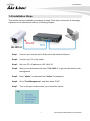
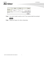
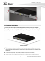
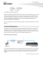
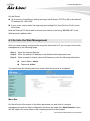
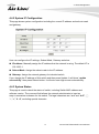
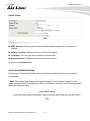
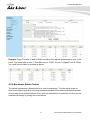
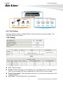
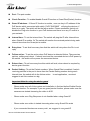
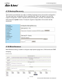
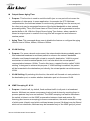
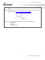
POE-FSH1008AT 8-port POE + 2 Combo Gigabit 802.3at Device Guard Web Smart Switch User’s Manual Copyright and Disclaimer Copyright & Disclaimer No part of this publication may be reproduced in any form or by any means, whether electronic, mechanical, photocopying, or recording without the written consent of OvisLink Corp. OvisLink Corp. has made the best effort to ensure the accuracy of the information in this user’s guide. However, we are not liable for the inaccuracies or errors in this guide. Please use with caution. All information is subject to change without notice All Trademarks are properties of their respective holders. i AirLive POE-FSH1008AT User’s Manual Copyright and Disclaimer FCC Statement Federal Communication Commission Interference Statement This equipment has been tested and found to comply with the limits for a Class A digital device, pursuant to Part 15 of the FCC Rules. These limits are designed to provide reasonable protection against harmful interference in a residential installation. This equipment generates uses and can radiate radio frequency energy and, if not installed and used in accordance with the instructions, may cause harmful interference to radio communications. However, there is no guarantee that interference will not occur in a particular installation. If this equipment does cause harmful interference to radio or television reception, which can be determined by turning the equipment off and on, the user is encouraged to try to correct the interference by one of the following measures: Reorient or relocate the receiving antenna. Increase the separation between the equipment and receiver. Connect the equipment into an outlet on a circuit different from that to which the receiver is connected. Consult the dealer or an experienced radio/TV technician for help. FCC Caution Any changes or modifications not expressly approved by the party responsible for compliance could void the user's authority to operate this equipment. This device complies with Part 15 of the FCC Rules. Operation is subject to the following two conditions: (1) This device may not cause harmful interference, and (2) this device must accept any interference received, including interference that may cause undesired operation. For product available in the USA/Canada market, only channel 1~11 can be operated. Selection of other channels is not possible. This device and its antenna(s) must not be co-located or operation in conjunction with any other antenna or transmitter. IMPORTANT NOTE FCC Radiation Exposure Statement: This equipment complies with FCC radiation exposure limits set forth for an uncontrolled environment. This equipment should be installed and operated with minimum distance 20cm between the radiator & your body. AirLive POE-FSH1008AT User’s Manual ii Table of Contents Table of Contents 1. Introduction .............................................................................................. 1 1.1 Overview............................................................................................ 1 1.2 Guide to the Chapters ........................................................................ 2 1.3 Quick Setup ....................................................................................... 2 1.4 Installation Steps................................................................................ 3 2. Installation of the Switch ......................................................................... 5 2.1 Unpack the Package .......................................................................... 5 2.2 Hardware Overview ........................................................................... 6 2.2.1 Front Panel .................................................................................................. 6 2.2.2 Rear Panel................................................................................................... 7 2.3 Installation Site Preparation ............................................................... 7 2.4 Rack Mounting ................................................................................... 8 2.5 Desktop Installation ........................................................................... 9 2.6 Cabling Requirements ..................................................................... 10 2.7 Connecting to Power ....................................................................... 10 2.8 Reset to Default ............................................................................... 10 3. LED Indicators ....................................................................................... 12 3.1 Comprehensive LEDs ...................................................................... 12 3.2 LED Table ........................................................................................ 12 4. Web Management .................................................................................. 13 4.1 Setup your Computer for Web management .................................... 13 4.2 Remote Management ...................................................................... 15 4.3 Get into the Web Management ........................................................ 17 4.4 Administrator.................................................................................... 18 4.4.1 Authentication Configuration ...................................................................... 18 4.4.2 System IP Configuration ............................................................................ 19 4.4.3 System Status ............................................................................................ 19 4.4.4 Load Default Setting .................................................................................. 20 4.4.5 Firmware Update ....................................................................................... 21 4.4.6 Reboot Device ........................................................................................... 21 iii AirLive POE-FSH1008AT User’s Manual Table of Contents 4.5 Port Management ............................................................................ 21 4.5.1 Port Configuration ...................................................................................... 22 4.5.2 Port Mirroring ............................................................................................. 23 4.5.3 Bandwidth Control ..................................................................................... 24 4.5.4 Broadcast Storm Control............................................................................ 25 4.6 PoE with Device Guard .................................................................... 26 4.6.1 PoE Setting................................................................................................ 27 4.6.2 PoE Power Delay ...................................................................................... 28 4.6.3 PoE Scheduling ......................................................................................... 28 4.6.4 Device Guard............................................................................................. 29 4.7 VLAN Setting ................................................................................... 31 4.7.1 VLAN Mode ............................................................................................... 31 4.7.2 VLAN Member ........................................................................................... 32 4.7.3 Multi to 1 Setting ........................................................................................ 36 4.8 Per Port Counter Port ...................................................................... 36 4.9 QoS Setting ..................................................................................... 38 4.9.1 Priority Mode ............................................................................................. 39 4.9.2 Port, 802.1p, IP/DS based ......................................................................... 39 4.9.3 TCP/UDP Port Based ................................................................................ 40 4.10 Security.......................................................................................... 42 4.10.1 MAC Address Binding .............................................................................. 42 4.10.2 TCP/UDP Filter ........................................................................................ 43 4.11 Spanning Tree ................................................................................ 44 4.11.1 STP Bridge Settings ................................................................................. 44 4.11.2 STP Port Settings .................................................................................... 46 4.11.3 Loopback Detection Settings ................................................................... 48 4.12 Trunk Setting ................................................................................. 48 4.13 Backup/Recovery........................................................................... 51 4.14 Miscellaneous ................................................................................ 51 4.15 Logout ........................................................................................... 53 Appendix A: Product Specifications ........................................................ 54 Appendix B: Troubleshooting................................................................... 56 AirLive POE-FSH1008AT User’s Manual iv 1. Introduction 1 1. Introduction 1.1 Overview The POE-FSH1008AT is a Power Control Active POE Switch. It was designed for easy installation and high performance in an environment where traffic is on the network and the number of users increases continuously. It consists of 8 10/100Mbps RJ-45 ports and 2 Gigabit RJ-45/ Gigabit SFP Combo Port. The 8 10/100Mbps RJ-45 ports are built with 48V Active PoE technology. That can solve the limitation of the power outlet location and offer the system designer a flexible solution to locate the network device everywhere. By the default, the PoE port's power is turned off, you must turn on the power through web management. This switch does not work with passive PoE devices; please make sure your device's PoE port can accept 802.3at/af PoE power. The compact rigid desktop size was specifically designed for small to medium workgroups. It can be installed where space is limited; moreover, it provides smooth network migration and easy upgrade to network capacity. The switch does not include the optional rack mount kit, it must be purchased separately. This user’s manual will help you to uncover most functions of the POE-FSH1008AT with step-by-step instructions presented by high quality illustrations. Thank you for choosing OvisLink’s product. 1 AirLive POE-FSH1008AT User’s Manual 1. Introduction * Note: This switch does not work with passive PoE devices. It uses 802.3at/af PoE standard Please make sure your device's PoE port can accept 48V active PoE power. 1.2 Guide to the Chapters Chapter 1: Introduction and Quick Setup guide. All the essential information including IP Address and Password information are in the Quick Setup section. Chapter 2: Detail installation instruction including how to make Cat. 5 Cable Chapter 3: LED indicators Chapter 4: Detail information on Web management including how to setup remote management. 1.3 Quick Setup This section provides the essential information for experienced users to operate the switch immediately. For detailed installation instruction, please see chapter 2 for more information. Power-On the switch The POE-FSH1008AT has a built-in power supply to operate with 100 ~ 240V AC, 50 ~ 60Hz power source. The AC power cord connector is located at the rear of the unit and the On/Off switch is next to the connector. After the Switch is powered on, it will perform “self-diagnostic” test. This process takes about 5 seconds to complete. LED Table LED Power Link/ ACT (Port 1-8) PoE Link/ ACT (G1-G2) Color/Status Amber On Green On Green Blinking Amber On Off Green On Green Blinking Description Power on Link Up Data activating Port is linked to Power Device No Power Device is connected Link Up Data activating Note : G1 is Port 9 and G2 is Port 10 AirLive POE-FSH1008AT User’s Manual 2 1. Introduction 1.4 Installation Steps This section lists the installation procedures in steps. Each step’s instruction is thoroughly explained in the subsequent sections of following chapter. Step1. Connect your device's active PoE port to the switch's LAN port Step2. Connect your PC to the switch. Step3. Set your PC's IP address to 192.168.2.50. Step4. Open your web browser and enter "192.168.2.1" to get into the switch's web management. Step5. Enter "admin" for username and "airlive" for password. Step6. Go to "Port Management", and then select "PoE". Step7. Turn on the port number where you connect the device. 3 AirLive POE-FSH1008AT User’s Manual 1. Introduction Step8. If you want to install the switch on the 19" rack, please install the mounting kit (optional). Step9. Please see Chapter 4 for further configurations. AirLive POE-FSH1008AT User’s Manual 4 2. Installation of the Switch 2 2. Installation of the Switch This chapter provides the detailed instructions for installation of the switch. For concise installation instruction, the previous chapter’s “Quick Setup” section provides all the important information including IP address, password, and LED table for user’s reference. 2.1 Unpack the Package Before you begin the installation of POE-FSH1008AT Management Switch, make sure that you have all the necessary accessories that come with your package. Follow the steps below to unpack your package contents: 1. Clear out an adequate space to unpack the package carton. 2. Open the package carton and take out the contents carefully. 3. Put back all the shipping materials such as plastic bag, padding and linings into the package carton and save them for future transport need. After unpacking and taking out the entire package contents, you should check whether you have got the following items: POE- FSH1008AT One AC Power Cord Quick Install Guide Support CD-ROM (The PDF version of this User’s Manual can be found within CD) If any of these above items is missing or damaged, please contact your local dealer for replacement. 5 AirLive POE-FSH1008AT User’s Manual 2. Installation of the Switch 2.2 Hardware Overview 2.2.1 Front Panel The front panel of the web smart switch consists of 8 10/100Base-TX RJ-45 ports. The LED Indicators are also located on the front panel. LED Indicators: Comprehensive LED indicators display the status of the switch and the network (see the LED Indicators chapter below). Front Ethernet Ports: The front panel of the web smart switch consists of 8 10/100Base-TX RJ-45 ports, 2 Gigabit RJ-45 and 2 Gigabit SFP uplink combo ports. 8 10/100Base-TX RJ-45 ports are PoE enable ports. These PoE ports will be automatically activated when a compatible terminal is identified, and the PoE port will supply power to the connected PoE device. For legacy devices that are not yet compatible, the PoE port will not offer the power to these devices. This feature allows users to freely and safely mix legacy and Power over Ethernet compatible devices on their network. These ports support network speeds of either 10Mbps or 100Mbps, and can operate in halfand full- duplex transfer modes. These ports also support the automatic MDI/MDIX crossover detection function, providing true “plug and play” capability. Just plug-in the network cable to the hub directly and regardless if the end node is a NIC (Network Interface Card) or switch and hub. Reset: The Reset button is to reset all the setting back to the factory default. AirLive POE-FSH1008AT User’s Manual 6 2. Installation of the Switch * Note: Be sure that you recorded the setting of your device, else all the setting will be erased when pressing the “Reset” button. 2.2.2 Rear Panel The 3-pronged power plug and on/off switch are placed at the rear panel of the switch right side shown as below. 2.3 Installation Site Preparation You can mount POE-FSH1008AT either on desktop or on a 19-inch rack. If you plan to mount the switch on desktop, please choose a steady, level surface in a well-ventilated area that is free from excessive dust. In any case, the installation site chosen for your switch has to comply with the following requirements: The surface where you want to mount the switch must be able to sustain at least 1.5kg. Do not place heavy objects (more than 3kg) on top of the switch. The location must preferably be free from excessive dust, away from heat vent, hot-air exhaust and direct sunlight. The switch should not be placed near large electric motors or other strong electromagnetic sources. As a reference, the strength of the electromagnetic field on site should not exceed the (RFC) standards for IEC 801-3, Level 2(3V/M) field strength. The air temperature in the location should be within a range of 0 to 65°C. The relative humidity in the location should not exceed 90% non-condensing humidity. The distance between the RJ-45 port and the standard network interface should not exceed 100 meters. Adequate space should be allowed in front of all the ports, so that each port is easily accessible for cable connections. Leave at least 10cm(4 inch) of space around the switch to allow heating dissipation 7 AirLive POE-FSH1008AT User’s Manual 2. Installation of the Switch 2.4 Rack Mounting The POE-FSH1008AT can be mounted on a standard size 19-inch rack, which can in turn be placed in a wiring closet with other equipment. Note: Mounting Kit is the optional accessory. Before you can mount the switch on the rack, first you must attach the mounting brackets on both sides of the switch with screws, and then mount it as a unit on the rack. To mount the unit on a rack, please follow the steps below: Step 1. First, align the holes on the bracket with the holes on both side of the switch. Step 2. Insert screws into the holes and then fasten the bracket on one side of the switch with a screwdriver. Step 3. Repeat Step 1 and 2 to fasten the bracket on the other side of the switch. Step 4. Mount the unit on the rack and align the notches on both brackets with mounting holes on the rack, and then secure the unit with suitable screws. Fastening the brackets on the switch AirLive POE-FSH1008AT User’s Manual 8 2. Installation of the Switch Attaching the Switch to a 19-inch rack 2.5 Desktop Installation The POE-FSH1008AT has four rubber pads attached on each corner of its underside. These pads serve as cushioning against vibration and prevent the switch from sliding off its position. They also allow adequate ventilation space when you place the switch on top of another device. Desktop installation The location you choose to install your switch and the way you configure your network may greatly affect its performance. Please see the previous section for “installation site” preparation. Do not place more than 1.5kg (6.6lbs) of weight on the top of the switch. Leave at least 10cm of space around the switch to allow proper heating dissipation. 9 AirLive POE-FSH1008AT User’s Manual 2. Installation of the Switch 2.6 Cabling Requirements For 100BASE-TX ports The 8 RJ-45 station ports require Cat. 5 twisted-pair UTP/STP cable for connection. When configuring within the 10/100 BASE-T cabling architecture, the cable distance should be within 100m. The following table summarizes the cable requirement for 10/100BASE-TX connection: 10BASE-T 100BASE-TX 100 ohm Category 3, 4, 5 UTP/STP cable 100 ohm Category 5 UTP/STP cable Auto MDI/MDI-X function The POE-FSH1008AT is equipped with Auto-MDI/MDI-X function, which allows you to use straight-thru cable even when connecting to another switch/hub. Simply use the straight-through cable for all types of 10/100BASE-TX connections, either to a PC or to a networking device such as other hub or switch. 2.7 Connecting to Power POE-FSH1008AT features a universal auto-select power supply unit, which allows a power connection to a wide range of input voltages from 100 to 240VAC @ 50 ~ 60Hz. To establish its power connection, simply plug the female end of the power cord into the power connector on the rear of the switch and the male end of the power cord into a suitable power outlet. Once you have correctly plugged in the power, you can then turn on the Power Switch to activate the switch. 2.8 Reset to Default When you forgot your IP or password, please use the reset button for the factory default setting? Please take the following steps to reset the Web Smart Switch back to the original default: Step 1. Turn on the POE-FSH1008AT. Step 2. Press and hold the reset button continuously for 10 seconds and release the reset button. AirLive POE-FSH1008AT User’s Manual 10 2. Installation of the Switch Step 3. The switch will reboot for 5 seconds and the configuration of switch will back to the default setting. Key in the user ID and the password to pass the authentication; the default ID and Password is as below, IP Address: 192.168.2.1 ID: admin Password: airlive 11 AirLive POE-FSH1008AT User’s Manual 3. LED Indicators 3 3. LED Indicators Before connecting any network device to POE-FSH1008AT, you should take a few minutes to look over this chapter and get familiar with the front panel LED indicators of your Switch. 3.1 Comprehensive LEDs 3.2 LED Table LED Power Link/ ACT (Port 1-8) PoE Link/ ACT (G1-G2) Color/Status Amber On Green On Green Blinking Amber On Off Green On Green Blinking Description Power on Link Up Data activating Port is linked to Power Device No Power Device is connected Link Up Data activating Note : G1 is Port 9 and G2 is Port 10 AirLive POE-FSH1008AT User’s Manual 12 4. Web Management 4 4. Web Management The POE-FSH1008AT can be configured by web based interface, including administrator, port management, VLAN setting, per port counter, trunk setting, QoS setting, security filter, configuration/ backup/recovery, miscellaneous, log out, and so on. The device based smart switch supports main stream browsers, such as IE, Firefox and Chrome…etc. to configure the device function. All functions are illustrated below. 4.1 Setup your Computer for Web management The Concept of Subnet Under the TCP/IP environment, network devices must be on the same subnet in order to see each other. This means before you can configure the switch through web browser, your must set your computer to the same subnet as the switch. For two network devices to be on the same subnet, they must have the following 2 criteria: Their IP address must be on the same subnet. For example, if one IP address is 192.168.2.1. The other’s IP address must be 192.168.2.x (x is any number between 2 and 254) for Class C subnet. To find out the IP address information for your computer. Under WinNT/2000/XP, please open Command Line window and type “ipconfig”. They must have the same subnet mask. For example, if one machine is 255.255.255.0. The other machine must also set to the same 255.255.255.0 mask. Configure your computer’s IP Before accessing the switch through web browser, please follow the instruction below to configure your computer’s IP to the same subnet as the switch. If your switch’s IP has not been changed, it should have the following factory default value: The switch’s Default IP IP Address: 192.168.2.1 Subnet Mask: 255.255.255.0 13 AirLive POE-FSH1008AT User’s Manual 4. Web Management Now if your computer’s IP is not in the same subnet as the switch, please follow the steps below to change the computer’s IP: STEP 3 STEP 2 STEP 4 STEP 1 Figure 4-1 Manual IP setting Step 1. Double click on the network connection status icon on the task bar. This should bring up a window showing the status of the current network connection. If there is no network status icon on the task bar, please go to the “Start -> Settings -> Network -> Local Connection” of the task bar’s Start menu. Step 2. Clock on the “property” icon. Step 3. Double click on the “Internet Protocol (TCP/IP) Step 4. Click on “Use the following IP address” button and enter the computer’s address manually. This IP address must be on the same subnet as the switch but different from the switch’s IP. Please make sure the IP is not used by other network device. If the switch’s IP address is of factory’s default value. We recommend enter the following for computer’s IP: AirLive POE-FSH1008AT User’s Manual 14 4. Web Management IP Address: 192.168.2.50 Subnet Mask: 255.255.255.0 Gateway: 192.168.2.1 Click “OK” after finish entering the IP. * Note1: The POE-FSH1008AT has DHCP client ability. This allows DHCP server (or router) to assign IP automatically. However, we do not recommend turning on the DHCP client because the DHCP server assign the IP randomly. The DHCP client should be used only when connecting directly to Cable Modem (for remote management) whose service provider uses DHCP for IP assignment. Now, you will be able to access the switch by typing in the switch’s IP address on the web browser. 4.2 Remote Management In this section, you will learn how to setup your computer and the router for remote web management. Remote management allows MIS to manage a switch from outside of the switch’s IP domain or from Internet. Depending on the type of Internet connection you have, there are two ways to setup the switch to be available through Internet. Direct Connection to Internet If you have a fixed IP xDSL account or cable modem account, and there is no router in the network, you can connect your switch directly to Internet via xDSL modem/Cable Modem. However, this method is not recommended as the LAN will be directly exposed to the Internet. 15 AirLive POE-FSH1008AT User’s Manual 4. Web Management Fixed IP: If your ISP has assigned you a fixed IP. Please go to the Switch’s IP configuration and enter the IP address, Subnet Mask, and Gateway information offered by your ISP. If your ADSL connection is PPPoE or PPTP type, you have to connect through a router for remote management. Cable Modem: If your Cable service provider uses DHCP for IP assignment, please turn on the DHCP function under IP configuration. Make sure there is no DHCP server in the network. Then the Cable provider will assign the switch with a IP and Gateway. Go to the console port management to find out what IP has been assigned to the switch. When the configuration is finished, the Remote PC can access the switch by typing the switch’s IP address on the web browser. Connect through Broadband Router If you have an IP sharing router in the network, you can open a virtual server on the router to allow the switch to be managed through Internet. This method is more recommended as the broadband router provides natural firewall protector from hackers. In the diagram above, the router has the WAN (given by the ISP) port IP address “201.100.1.5” and LAN port address “192.168.0.254”. The switch’s IP is “192.168.0.200”. Please follow the instruction below to setup the router and switch for remote access: On the Switch On the IP setting, set the gateway to Router’s LAN port address 192.168.0.254. Please make sure the subnet mask is the same as the routers. AirLive POE-FSH1008AT User’s Manual 16 4. Web Management On the Router Go to router’s Virtual Server setting and open the Web port (TCP Port 80) to the switch’s IP address 192.168.0.200. If your router require enter the beginning and ending Port (from PortX to PortX), enter 80 for both. Now the Remote PC will be able to access your switch by entering “201.100.1.5” in the Web browser’s address field. 4.3 Get into the Web Management After you have properly configured the computer and switch’s IP, you can get into the web management by the following steps: Step 1. Open the Internet Explorer Step 2. Enter the switch’s IP address in the Address field and press enter. Step 3. When prompt for User’s name and Password, enter the following information: User’s Name: admin Password: airlive You should see the following welcome screen after the process is completed: Menu Bar On the left side of the screen is the Menu bar where you and click to configure management functions. Most configuration functions are under the “Administrator” menu. We will explain the menu items in the remaining section of this chapter. 17 AirLive POE-FSH1008AT User’s Manual 4. Web Management Top Switch Image The switch’s image on the upper portion of the screen gives the quick overview of the port connection status. When a port is plugged in, the switch’s image will show a “plug” on the corresponding port. 4.4 Administrator There are many management functions can be set or performed if you click the Administrator on Home Page, including: Authentication Configuration System IP Configuration System Status Load Default Setting Firmware Update Reboot Device In the following sessions, we will talk in detail about the management functions under the Administrator menu. 4.4.1 Authentication Configuration This page shows authentication configuration information. User can set new Username and Password in this page. AirLive POE-FSH1008AT User’s Manual 18 4. Web Management 4.4.2 System IP Configuration This page shows system configuration including the current IP address and sub-net mask and gateway. User can configure the IP settings, Subnet Mask, Gateway as below: IP address: Manually assign the IP address that the network is using. The default IP is 192.168.2.1 Subnet Mask: Assign the subnet mask to the IP address. Gateway: Assign the network gateway for industrial switch. If you change the IP address of this switch and then press Update. It will show “update successfully” then press Reboot button. It will enter user login screen automatically. 4.4.3 System Status This page is used to check the status of switch, including Switch MAC address and software version. The comment field allows the network administrator to input an easy-to-remember nickname for this switch. The legal characters are “a~z” and “A~Z”, “_”, “-“, “+”, “0 ~9”, excluding special character. 19 AirLive POE-FSH1008AT User’s Manual 4. Web Management MAC Address: Displays the unique hardware address assigned by manufacturer (default). Number of Ports: Displays number of ports in the switch. Comment: You can type some comment for the switch. System Version: Displays the switch’s firmware version. And then click Update button. 4.4.4 Load Default Setting Configuration Clicking the “Load” button will make the switch being set to the original configuration. * Note: This change only concerns the switch behavior, excluding the change for user name, password and IP configuration. After Load Default is executed, the all settings will be restored to default setting. AirLive POE-FSH1008AT User’s Manual 20 4. Web Management 4.4.5 Firmware Update Before the firmware update procedure is executed, you should enter the password twice and then press Update button. The smart switch will erase the flash memory. There is a self-protection mechanism in the Boot Loader, so the Boot Loader will keep intact. Even though the power is turned off or the cable link fails during the firmware update procedure, the Boot loader will restore the code to firmware update page. After pressing Update button, the old web code will be erased. Then you can select the image file and press “Update” button to update the firmware you need. 4.4.6 Reboot Device Click “Confirm" button to reboot the device. * Note: The reboot is for software base instead of hardware base 4.5 Port Management There are many management functions can be set or performed if you click the Port Management on Home Page, including: Port Configuration Port Mirroring Bandwidth Control Broadcast Storm Control In the following sessions, we will talk in detail about the management functions under the Port Management menu. 21 AirLive POE-FSH1008AT User’s Manual 4. Web Management 4.5.1 Port Configuration In Port Configuration, you can set and view the operation mode for each port. Tx/Rx-Ability: Enable or Disable. The default value is "Enable". Being set as "Enable", the port can Transmit and Receive packet without any problem. After changed to "Disable", the selected ports cannot access the network anymore. Auto-Negotiation: Enable and Disable. Being set as ‘Enable’, the Speed, Duplex mode, Pause, Backpressure, TX Capability and Address Learning are negotiated automatically. When you set it as ‘Disable’, you have to assign those items manually. Speed: When the Auto-Negotiation column is set as Disable, users have to set the connection speed to the ports ticked. Duplex: When the Auto-Negotiation column is set as Disable, users have to set the connection mode in Half/Full to the ports ticked. Pause: Flow Control for connection at speed of 10/100Mbps in Full-duplex mode. Backpressure: Flow Control for connection at speed of 10/100Mbps in Half-duplex mode. Addr. Learning: When the Auto-Negotiation column is set as Disable, users have to set this column as Enable or Disable. Select Port No.: Tick the check boxes beside the port numbers being set. AirLive POE-FSH1008AT User’s Manual 22 4. Web Management Current Status: Displays the status of each ports. This field indicates the port 9 is link up and run as 1G Full, Flow Control Enabled. Current Status: Displays current port status. Setting Status: Displays current status. Click "Update" to have the configuration take effect. 4.5.2 Port Mirroring The port mirroring function is accomplished by setting the following items. 23 AirLive POE-FSH1008AT User’s Manual 4. Web Management Destination port: Theoretically it’s possible to set more than one destination port in a network. Actually the port mirroring function will lower the network throughput, and therefore it’s recommended to set “only one” destination port in a network. Monitored packets: i. Disable: means this function is disabled. ii. RX: means copy the incoming packets of the selected source port to the selected destination port. iii. TX: means copy the outgoing packets of the selected source port to the selected destination port. iv. RX & TX: means the combination of Rx and Tx. Source port: the traffic source that will be copied to the destination port. Take the following configuration as an example. i. Source port: Port 1 ~ Port 4. ii. Destination Port: Port 5 ~Port 8. iii. Mirrored packet: Rx. This means all packets received at port 1 ~port 4 will be copied to port 5, port 6, port 7 and port 8.Care should be taken that the more source ports and destination ports is set, the lower network throughput is available for normal traffic. 4.5.3 Bandwidth Control This page allows the setting of the bandwidth for each port. The TX rate and Rx rate can be filled with the number ranging from 1 to 255. This number should be multiplied by the selected bandwidth resolution to get the actual bandwidth. AirLive POE-FSH1008AT User’s Manual 24 4. Web Management Example: Type 5 for both Tx and Rx Rate and select the High as speed base for port 1 and port 9. The actual rate for port 1 (Fast Ethernet) is "1280", for port 9 (Gigabit Port) is 10240. You could see the table is updated as below. 4.5.4 Broadcast Storm Control The switch implements a broadcast storm control mechanism. Tick the check boxes to have them beginning to drop incoming broadcast packets if the received broadcast packet counts reach the threshold defined. Each port’s broadcast storm protection function can be enabled individually by ticking the check boxes. 25 AirLive POE-FSH1008AT User’s Manual 4. Web Management The broadcast packet is only checked at the selected port and the number of broadcast packets is counted in every time unit. One time unit is 500 us for 10Mbps speed and 5ms for 100Mbps. The excessive broadcast packet will be discarded. For those broadcast packets incoming from the un-selected port, the switch treats it as the normal traffic. Threshold: Type in the threshold in the range between 1 and 63 to limit the maximum byte counts, which a port can send or receive in a period of time. Enable Port: Having ticked the boxes, the port will stop transmitting or receiving data when their sending byte counts or receiving byte counts reach the defined threshold. Click Update to have the configuration take effect. Example to change one time unit to pps: The port 1 is 100M port. The one time of it is 500us, it indicates there are 2,000packets can be sent within one second. While type 10 to port 1, that means 10x2000 packets can be sent in one second. 4.6 PoE with Device Guard There are many PoE functions can be set when you click the PoE including the PoE Setting, PoE Power Delay, PoE secluding and Device Guard Device Guard function can monitor PoE IP cameras and Access Points activities. When device crashed or not responding, it will reboot the device automatically. AirLive POE-FSH1008AT User’s Manual 26 4. Web Management 4.6.1 PoE Setting This page allow to enable or disable PoE per port and set the max power budget. This Page also displays Port status. Port: The port number. Enable: Enable PoE feature of the specific ports. The default value is ON for all ports.If there is any standard PoE device is detected, the LED of PoE is turn to amber. Power Consumption: The output power of the port. It is the power consumption of the connected device. PoE Class: The PoE class of the connected port. 27 AirLive POE-FSH1008AT User’s Manual 4. Web Management Priority: User can set the PoE priority from 1 ~ 3 , if total connected devices consumption power exceed the max. available power , the critical devices will provide the power first 4.6.2 PoE Power Delay PoE-FSH1008AT can set how many second delay the switch will provide the power output for connection devices when the switch is power on. Port: The port number Delay Mode: To enable or disable the delay mode. Delay Time: To set how many seconds the power will be delayed for connected devices after PoE-FSH1008AT’s power on. 4.6.3 PoE Scheduling This page can set PoE Power On/off schedule. To Set up this page , please make sure , the switch’s system time is in the right time. To set up the switch’s system time , you need to enable the NTP. Detail NTP setting , please refer chapter 5.14 AirLive POE-FSH1008AT User’s Manual 28 4. Web Management 4.6.4 Device Guard There are two device guard methods to guard your PoE devices. One is guard Packet the other is guard IP. When Guard Pkts is enabled, the switch will do the failure action if there is no any incoming packet at each port for a period (interval time). When the guard IP is enabled , the switch will try to ping the IP , if the IP is not reply , the switch will do the failure action. 29 AirLive POE-FSH1008AT User’s Manual 4. Web Management Port : The port number Check Function : To enable/disable Guard IP function or Guard Pket(Packet) function Guard IP address : If Guard IP function is enable , user can key in IP address of the PoE device which connected with switch. PoE-FSH1008AT will ping the devices, if there is no reply. The switch will do the failure action. Please remember that do not disable the Ping echo function in your PoE devices and there is no any IP conflict in your network. Interval time : To set the interval time. The switch will ping the IP after Interval time when Guard IP is enable. Or The switch will monitor the received packet during each interval time when the Guard pkt is enable. Retry time : To set that how many time that the switch will retry when the Pin is not reply. Failure action : To set the action when PoE device is detected failure. There are two opinion, nothing and reboot . If reboot is set and the connected device is PoE power by the switch , the switch will re-power the connected device. Reboot time : To set how many time this switch will wait, when reboot is required by device guard function Packet Setting : To set the Packet numbers. When Guard Pkts is enabled, if switch receiving packets in the port is lower than the Packet Setting number during each Interval time, the switch will do the failure action. In real application , we donot suggest to set this number too big. Important Note for using the device guard - Please make sure all of the system and installation is finished before Enable Device Guard function. For example, if you are guard packet function, please make sure the cameras are started streaming the video to NVR. - Please make sure Ping Response is not disabled when using Guard IP - Please make sure video is started streaming when using Guard Pkt mode - If you connected devices are access point , we suggest to use guard IP. AirLive POE-FSH1008AT User’s Manual 30 4. Web Management 4.7 VLAN Setting A Virtual LAN (VLAN) is a logical network grouping that limits the broadcast domain, which would allow you to isolate network traffic, so only the members of the same VLAN will receive traffic from the ones of the same VLAN. Basically, creating a VLAN from a switch is logically equivalent of reconnecting a group of network devices to another Layer 2 switch. However, all the network devices are still plugged into the same switch physically. There are many management functions can be set or performed if you click the VLAN Setting on Home Page, including: VLAN Mode VLAN Member Multi to 1 Setting In the following sessions, we will talk in detail about the management functions under the VLAN Setting menu. 4.7.1 VLAN Mode You may select the VLAN Mode of the switch. Port-based VLAN is for separating traffic only on this single switch. There is no handover of network traffic within VLAN groups to other switches. For the handover to other switches use Tag Based VLAN. In VLAN Mode you can switch from Tag to Port Based VLAN. Port Based VLAN is the default mode. After having switched to Tag Based VLAN Mode, the screen changes. On this screen you can now define and configure your Up and Downlink ports. These are important since here the handover between the switches of your network takes place. Tag Based VLAN Mode 31 AirLive POE-FSH1008AT User’s Manual 4. Web Management VLAN Mode: Displays VLAN mode: port based/Tag based VLAN. Here you can also switch back to Port Based VLAN Mode Tag Mode: Add Tag: The outgoing packet of the selected port will be inserted a 802.1Q tag. Use this setting for your Up and Downlink Ports in your VLAN Tagged Network. Don’t care: Don’t care means the outgoing packet of the selected port keep the original packet received at the source port. This is the default setting when starting VLAN configuration. You should change to either Add or Remove Tag. Remove Tag: Remove tag means the 802.1Q tag of the outgoing packet of the selected port will not be sent. Use this setting for your Network Connections to PCs. Only packets of the VLAN Group the Port is member of will be sent. 4.7.2 VLAN Member The ports need to be made member of your VLAN groups. This is for Tag Based and Port Based VLAN Mode. The screen here looks different whether you run Tag Based or Port Based Mode. AirLive POE-FSH1008AT User’s Manual 32 4. Web Management VLAN Member in Port Based Mode In Port Based Mode you see a matrix of your 8 Ports. Simply select the port on top screen you want to configure, click on Read, and then select or deselect the ports that are on the same VLAN group. In this configuration mode you do not need to worry about defining VLAN groups and VLAN IDs. VLAN Member in Tag Based Mode In Tag Based Mode you need to define and configure your VLAN groups. Since you want the handover to other switches take place smoothly, the VLAN IDs (Numbers) need to be like on the rest of your network. On other switches you may have the chance to configure names. These are just for your reference. Only the numbers are important! 33 AirLive POE-FSH1008AT User’s Manual 4. Web Management VLAN ID (VID): Since you want the handover to other switches take place smoothly, the VLAN IDs (Numbers) need to be like on the rest of your network. (On other switches you may have the chance to configure names. These are just for your reference. Only the numbers are important!) Add: Enter a VID, select the VLAN member for this entry and then press this button to add a VLAN entry to the table. The available range of VID is from 1-4094. Delete: Select a VID in the table and then press this button to remove a VID entry from the table. After deleted, the VLAN and its member port setting is gone. Update: Modify the existing VLAN setting. Select the VID, the below settings display, you can change the settings and then press the Update button to update the settings. VLAN Member Port Select: Select the VLAN Member here. AirLive POE-FSH1008AT User’s Manual 34 4. Web Management VID Source Port: This table allows you to configure PVID of the port. Select the port number while you add VLAN and select VLAN member ports, the selected ports' PVID will be the VID you typed. * Please note that one port only can have one PVID. While one port joins multiple VLAN groups, the PVID is important to identify where the incoming traffic will be forwarded to. For example: Port 3 is the member of VLAN 100 and 200, PVID of it is 100. The traffic received from the connected PC is usually untagged; the incoming packets will then be tagged with PVID within the switch and then follow the VID table to forward traffic. Port VID Map: This table shows the PVID of the ports. VLAN Member Table: This table shows the VID and its member ports. Configuration Steps: First, add your VLAN Groups (identified throughout your network by unique and constant numbers). Start with IDs from 100 and up is often. Starting with 100 gives you enough free room and less compatibility issues. Second, enter “100” in the field right of VID Setting, then select or deselect which ports are member of that group. Your up and downlink ports need to be the member of every existing group. If the port joins different VLAN groups, the VID Source Port allows you to define the PVID. 35 AirLive POE-FSH1008AT User’s Manual 4. Web Management After configured and selected, then click on Add to create the table and related port mapping. The new group with its setting will be displayed at the bottom of the screen. 4.7.3 Multi to 1 Setting Multi to 1 VLAN is used in CPE side of Ethernet-to-the-Home and is exclusive to VLAN setting on VLAN Member Setting. When VLAN Member Setting is updated, multi to 1 setting will be void and vice versa. The disable port means the port which will be excluded in this setting. All ports excluded in this setting are treated as the same VLAN group. In a normal Tag Based VLAN network you will not need this configuration option. 4.8 Per Port Counter Port This page provides port counter for each port. There are 4 groups of statistics in total. These 4 categories cannot work simultaneously. Once you change the counter category, the counter will be cleared automatically. AirLive POE-FSH1008AT User’s Manual 36 4. Web Management Transmit packet & Receive packet: This category shows both the received packet count (excluding the incorrect packet) and the transmitted packet count. Collision Count & Transmit packet: This category shows the packets outgoing from the switch and the count of collision. Drop packet & Receive packet: This category shows the number of received valid packet and the number of dropped packet. CRC packet & Receive packet: This category shows the received correct packet and received CRC error. Once your see CRC error increasing here, please notice that there may be hardware issue, the possible reason could be switch port failure, cable lose/broken, cable/fiber connector failure...etc. Update: Select the existing Counter Mode and click Update, the below statistic table will be updated. 37 AirLive POE-FSH1008AT User’s Manual 4. Web Management Clear: Press “clear” will clear all counters. Refresh: Press “Refresh” button will aggregate the number of the counter for all ports. 4.9 QoS Setting Here you can configure QoS policy priority mode and CoS (Class of Service) configuration. QoS (Quality of Service) refers to mechanisms in the network software that make the actual determination of which packets have priority. CoS refers to feature sets, or groups of services, that are assigned to users based on company policy. If a feature set includes priority transmission, then CoS winds up being implemented in QoS functions within the routers and switches in the network. In an enterprise network, class of service (CoS) differentiates high-priority traffic from lower-priority traffic. Tags may be added to the packets to identify such classes, but they do not guarantee delivery as do quality of service (QoS) functions, which are implemented in the network devices. There are many management functions can be set or performed if you click the QoS Setting on Home Page, including: Priority Mode Class of service Configuration In the following sessions, we will talk in detail about the management functions under the QoS Setting menu. AirLive POE-FSH1008AT User’s Manual 38 4. Web Management 4.9.1 Priority Mode There are three priority modes available to specify the priority of packets being serviced. Those include First-In-First-Out, All-High-Before-Low, and Weight-Round-Robin. First-In-First-Out: Packets are placed into the queue and serviced in the order they were received. All-high-before-low(Strict priority):All packets will be assigned to either high priority queue (Queue 2) or low priority queue (Queue 1). The packet on the low priority queue will not be forwarded Weight-Round-Robin (WRR) mode: There are 2 priority queues, Low and High for Weighted-and-round-robin (WRR) mode. When this mode is selected, the traffic will be forwarded according to ratio of the number set of Low/High weight user configured. 4.9.2 Port, 802.1p, IP/DS based The page allows you to enable Port Based, VLAN Tag or IP/DS mode of COS. 39 AirLive POE-FSH1008AT User’s Manual 4. Web Management =Enable High Priority. After Enabled High Priority, the following enabled Port Based parameter will become High Priority. Port Base: The selected port equipped with High Priority. The non-selected port is Low priority. A packet received by a high priority port is handled as a high priority packet. VLAN Tag: The switch follows the VLAN tag of the incoming packets to forward traffic. VLAN Tag priority: high priority -> 4~7 ; low priority -> 0~3 IP/DS: The switch follows the IP TOS / Diff Serve of the incoming packets to forward traffic. The number set of the high priority is 10,18,26,34,46,48,56; the others are mapped to low priority. 4.9.3 TCP/UDP Port Based This page allows user to define the Option type of the pre-defined protocols or user-defined protocols. Select the Option of the Protocol as below figure shown. AirLive POE-FSH1008AT User’s Manual 40 4. Web Management The Class of Service for TCP/UDP port number allows the network administrator to assign the specific application to a priority queue. F-I-F-O: The incoming packet will be forwarded in first-in-first-out scheme. Discard: The incoming packet will be discarded at the source port. High: The incoming packet will be forwarded with the high priority. Low: The incoming packet will be forwarded with the Low priority. User_Define x: We can define the port number and mask by ourselves. The Port defines the TCP/UDP Port number. The mask defines which bit is ignored within the IP address bit 0 ~ bit 7. For example, UDP/TCP port = 65535(Hex 0xFFFF = 11111111 11111111) and mask = 5 (Hex 0x0005 = 00000000 00000101), this means 65530 (11111111 11111010), 65531(11111111 11111011), 65534(11111111 11111110) and 65535(11111111 11111111) are all taken into account. UDP/TCP port =65535 and mask=0, this means only 65535 is taken into account. 41 AirLive POE-FSH1008AT User’s Manual 4. Web Management 4.10 Security There are many management functions can be set or performed if you click the Security on Home Page, including: MAC Address Binding TCP/UDP Filter In the following sessions, we will talk in detail about the management functions under the Security menu. 4.10.1 MAC Address Binding This function provides a method for the administrator to specify the relationship between the physical port and the MAC address. Only the packet with specified source MAC address can be forwarded. By specifying the MAC address to each port, the network administrator can prevent the unauthorized user from accessing the switch. Each port can correspond to up to 3 MAC addresses. To activate the port binding function, you should enter the correct MAC address, select the port number, and set the port binding to “enable” and then press “update”. MAC Address: Users can assign up to 3 MAC addresses to the port. Select Port: Select the port number and click "Read" button. If you don't enter any MAC Address before, the address is blank. If you have entered any MAC address, the field will display the MAC addresses your previously entered. AirLive POE-FSH1008AT User’s Manual 42 4. Web Management Read: Pull down the selection bar to choose a port number and click the read button to show the MAC addresses bound with the port or modify the MAC addresses. Binding: Enable or disable the binding function. After selected the port, enabled Binding and entered MAC Address, click "Update" to update and save the settings. * Note: Setting the multicast address to these fields is not allowed. A warning message will show up if you do so. 4.10.2 TCP/UDP Filter By selecting the TCP/UDP port, the network administrator can optionally block some specific applications. There are two kinds of protocol filter functions. The”forward” function makes the switch forward the selected protocol and drops other protocols. The” deny” function makes the switch drop the selected protocol and forward other protocols. The protocol is checked at the selected secure WAN port. And it should be set at the server side. 43 AirLive POE-FSH1008AT User’s Manual 4. Web Management Function Enable: To Enable or Disable the function. Port Filtering Rule: The outgoing packet with selected protocol will be either forwarded or dropped at secure WAN port as the figure shown below. "Negative" means the selected protocol will be dropped and other protocols will be forwarded. "Positive" means the selected protocol will be forwarded and other protocol will be dropped. Protocol: Select the pre-defined known protocol or User_Define Protocol number. Secure WAN Port: The port number of the Secured WAN Port. The secured WAN port is the Egress Port. The configured limit packet will be dropped. Click Update to have the configuration take effect. 4.11 Spanning Tree The switch supports IEEE 802.1D-2004 RSTP protocol, the RSTP protocol can backward compatible to legacy Spanning Tree Protocol (STP) and 802.1w Rapid Spanning Tree Protocol (RSTP). 4.11.1 STP Bridge Settings The Table allows you to configure STP Mode and the system time settings. AirLive POE-FSH1008AT User’s Manual 44 4. Web Management STP Mode: Disable, STP and RSTP. Select the STP version you want to enabled. Bridge Priority: This parameter configures the spanning tree priority globally for this switch. The device with the highest priority becomes the STP root device. However, if all devices have the same priority, the device with the lowest MAC address will then become the root device. Number between 0 - 61440 in increments of 4096. Therefore, there are 16 distinct values. Hello Time: Interval (in seconds) at which the root device transmits a configuration message (BPDU frame). Number between 1-10 (default is 2). Max Age – The maximum time (in seconds) a device can wait without receiving a configuration message before attempting to reconfigure. That also means the maximum life time for a BPDU frame. Number between 6-40 (default is 20). Forward Delay: The maximum time (in seconds) the root device will wait before changing states (i.e., discarding to learning to forwarding). Number between 4 – 30 (default is 15) Click Update to have the configuration take effect. The below table shows the Bridge Status and Root Switch's Status. The Bridge Status shows the STP configuration of the switch. The Root Status shows the Root Switch's Information of the STP domain. 45 AirLive POE-FSH1008AT User’s Manual 4. Web Management 4.11.2 STP Port Settings The STP Port Setting page allows you to change the port priority and its path cost. After STP/RSTP is enabled, the system automatically assigns the port priority and path cost to the prot. Normally, it is necessary to change the parameters, however, you may need to control the root switch or block port in some condition. This page allows you to change the STP port setting. Select the port number, type the value of the Priority and Root Path Cost. Click "Submit" to apply the settings. AirLive POE-FSH1008AT User’s Manual 46 4. Web Management Port No: The port ID. It cannot be changed. Aggregations mean any configured trunk group. Root Path Cost: This parameter is used by the STP to determine the best path between devices. Therefore, lower values should be assigned to ports attached to faster media, and higher values assigned to ports with slower media. Set the RSTP path cost on the port. Number between 0 - 200000000. 0 means auto generated path cost. Priority: Show the value of the Port Priority. Ex: 0x80 is 128. State: Show the current port state includes Designated port, Root port or Blocked port. Status: Show the current port status includes Forwarding, Disable, Blocking...etc. Designated Bridge: The field shows the MAC Address of the designated bridge (switch). Designated Port: The field shows the designated port number. 47 AirLive POE-FSH1008AT User’s Manual 4. Web Management 4.11.3 Loopback Detection Settings In some condition, the user may incorrectly connect the wrong port and lead the network loop. The unknown broadcast, multicast may crash the whole network. The Loopback Detection feature can help you leave the risk. Loopback Detection Function: This column allows you to enable or disable Loopback Detection function. Auto Wake Up: Once the Loopback Detection function is running, the ports maybe disabled to avoid the loop. The Auto Wake Up allows you to activate the port after Time Interval passed. Wake-Up Time Interval: Select the time interval here. Click "Submit" to apply the settings. 4.12 Trunk Setting Port trunk allows multiple links to be bundled together and act as a single physical link for increased throughput. It provides load balancing, and redundancy of links in a switched inter-network. Actually, the link does not have an inherent total bandwidth equal to the sum of its component physical links. AirLive POE-FSH1008AT User’s Manual 48 4. Web Management Traffic in a trunk is distributed across an individual link within the trunk in a deterministic method that called a hash algorithm. The hash algorithm automatically applies load balancing to the ports in the trunk. A port failure within the trunk group causes the network traffic to be directed to the remaining ports. Load balancing is maintained whenever a link in a trunk is lost or returned to service. This switch may use Port ID, Source MAC Address, Destination MAC Address, or a combination of Source MAC Address and Destination MAC Address to be the selection for Trunk Hash Algorithm. Traffic pattern on the network should be considered carefully before applying it. When a proper hash algorithm is used, traffic is kind of randomly decided to be transmitted across either link within the trunk and load balancing will be seen. This switch supports one trunk group, port 9 and Port 10. Trunk hash algorithm support Source MAC, Source & Destination MAC Address. System Priority: This column allows you to enable or disable Loopback Detection function. 49 AirLive POE-FSH1008AT User’s Manual 4. Web Management Link Aggregation Algorithm: MAC Src: Hash Algorithm based on Source MAC Address. MAC Src&Dst: Hash Algorithm based on Source & Destination MAC Address XOR result. Member: This column allows you to select the member Ports. Status: This column allows you to Enable/Disable the Trunk Group. Type: This column allows you to choose Static Trunking or Dynamic LACP Trunking. After Select the LACP Trunk type, the following parameters can be configured. Please noted that the parameters of the both ends of the LACP should be the same. Operation Key: This column allows you to type operation key. Time Out: This column allows you to select Long Time Out Time or Short Time Out Time. The Long Time Out is around 30 seconds, the Short Time Out is around 3 seconds, however, the link partner of other supplier may not use the same value. The longer time then will be used. Activity: This column allows you to select Passive or Active mode. * Note: If you enable LACP on some specified ports and their link partners are normal port without LACP, these specified ports cannot transmit packet to/receive packet from the link partner. AirLive POE-FSH1008AT User’s Manual 50 4. Web Management 4.13 Backup/Recovery This function provides the user with a method to backup/recovery the switch configuration. The user can save configuration file to a specified file. If the user wants to recover the original configuration, which is saved at the specified path, just enter the password and then press the “Update” button. Finally the original configuration of the switch will be recovered. 4.14 Miscellaneous Miscellaneous setting is used to configure output queue aging time, VLAN stride and IGMP snooping. 51 AirLive POE-FSH1008AT User’s Manual 4. Web Management Output Queue Aging Time: Purpose: This function is used to avoid the traffic jam on one port will not cause the congestion of other ports. In some application, for example the IPTV Multicast communication, the multicast stream is continuously generating from the source port, the client port may be congested because of the limited bandwidth or slow network processing ability. Then, the Pause frame of Flow Control will be generated once the packet buffer is full. With the Output Queue Aging Time feature, when a packet is stored at output queue in a switch for a long time will be aged out and become a useless packet. Aging Time: This command allows user to disable the feature or configure the aging timeout time to 200ms, 400ms, 600ms or 800ms. VLAN Striding: Purpose: For some network environment, the network administrator probably want to filter undesired broadcast or multicast packet to enhance the network bandwidth utilization and forward meaningful unicast to a specific destination. VLAN is a good mechanism to block broadcast packet, but it can also block the unicast packet communication between VLANs. To solve this issue, a special function called “VLAN striding” is designed to achieve this purpose. If VLAN striding is enabled, the packet will be forwarded to the destination port directly, the unicast packet can stride across VLAN. VLAN Striding: By selecting this function, the switch will forward uni-cast packets to the destination port, no matter whether destination port is in the same VLAN. IGMP Snooping V1 & V2: Purpose: A switch will, by default, flood multicast traffic to all ports in a broadcast domain. Multicast can cause unnecessary load on host devices by requiring them to process packets they have not solicited. The IGMP snooping is a feature that allows the switch to listen in on the IGMP conversation between hosts and routers. By listening (also known as snooping) to these conversations, the switch maintains a map of which ports (clients) need which multicast stream (source). Multicast may be filtered which do not need them, Multicast may be forwarded only to the IGMP group it joined. AirLive POE-FSH1008AT User’s Manual 52 4. Web Management IGMP Snooping: When this function is enabled, the switch will execute IGMP snooping version 1 and version 2 without the intervention of CPU. The IGMP report and leave packets are automatically handled by the switch. The next setting, IGMP Leave Packet can be enabled or disabled. After enabled, the Leave packet will be forwarded to IGMP router ports. NTP Setting: NTP setting is to set the NTP server, then the switch’s system time will sync with NTP. After NTP setting is set, please make sure that the Time Zone is correct. Especially if you want to use PoE scheduling. VLAN Uplink: Purpose: This switch does not implement Independent VLAN (IVL) MAC address table, it utilizes VLAN uplink to emulate the function of IVL. An independent VLAN MAC address table is based on both the source MAC address and the VLAN. In some application, if the Ethernet switch cannot build the separate MAC address table for different VLANs, there will be a conflict of MAC address table. To solve this problem, the switch controller utilizes the VLAN Uplink port to emulate the usage of Independent VLAN MAC Address Table. VLAN Uplink Setting: If VLAN uplink function is enabled and the destination port of an unicast packet is located at the next VLAN, this packet will be forwarded to the uplink port. Choose the Uplink Port X for the port ID. The Uplink X will be the uplink port of its VLAN. *Note: There is a functional conflict between VLAN striding and VLAN uplink. Imagine what will happen if both VLAN striding and VLAN uplink are enabled simultaneously? In this case, the switch selects VLAN striding and ignores the VLA 4.15 Logout The administrator has write access for all parameters governing the onboard agent. User should therefore assign a new administrator password as soon as possible, and store it in a safe place. 53 AirLive POE-FSH1008AT User’s Manual Appendix A: Product Specifications A Appendix A: Product Specifications Standards Features Smart Features Filtering/Forwarding Rates IEEE 802.3 10BaseT IEEE 802.3u 100BaseTX IEEE 802.3x Flow Control IEEE 802.3ad Trunk (Link Aggregation) IEEE 802.1q VLAN (Port Based and Tag Based) IEEE 802.1p Class of Service, Priority Protocols IEEE 802.1x IEEE 802.1d Spanning Tree Protocol IEEE 802.1w Rapid Spanning Tree Protocol Number of Ports: 8 802.3at Power over Ethernet Ports MAC Address: 4K Buffer Memory: 2.75M bits Transmission Method: Store and Forward Port VLAN: 8 Tagged VLAN: 4094 Trunk Groups : 2 (1~4 port for each group) Quality of Service: up to 4 queues PoE function ON/OFF Remote Control, power consumption, short protection STP/RSTP (Spanning Tree Protocol and Rapid Spanning Tree Protocol) MAC Filtering IGMP Snooping Management: Broadcast Strom Control, Bandwidth Control, Port Mirroring, Password-protected Access, Port Settings, Web-based Management, Graphic User Interface, Configuration Back and Restore…etc. 1000Mbps port - 1,488,000pps 100Mbps port - 148,800pps 10Mbps port - 14,880pps AirLive POE-FSH1008AT User’s Manual 54 Appendix A: Product Specifications Led Indicators Power Input Per Port: Link/Act, PoE Act/Status Per Unit: Power 100~240V/AC, 50~60Hz Power Consumption 48V/DC Per Port Output – 30 W Max Per Port 8 Port total 130W 130 Watts (Max) for PoE; Temperature Operating:0 to 45℃ Power Output Storage: -20 to 90℃ Humidity 10 to 90% RH (non-condensing) Certifications FCC Class A, CE Dimensions 263 × 160 × 44 mm (L x W x H) Weight 1.45 kg 55 AirLive POE-FSH1008AT User’s Manual Appendix B: Troubleshooting B Appendix B: Troubleshooting This appendix contains specific information to help you identify and solve problems. If your switch does not function properly, please make sure it is set up according to the instructions on the manual. Q: If you suspect your switch is not connected correctly to your network, check the following points before you contact your local dealer for support. A: Make sure the Power is ON (Check the Power LED). Make sure the cable is connected properly on both ends. Make sure that the maximum cable length between switch and end node does not exceed 100 meters (for 10/100/1000BASE-TX connection). Make sure that the maximum switch-to-hub/switch cable distance does not exceed 100 meters (for 10/100 BASE-TX connection). Verify that the cabling type used is correct. Check the corresponding Link/Act, FDX/Col, and 100M for signs of faulty connection. Check the status of the cable attachment. If the problem persists, try a different cable. Try another port on the Switch. Turn off power supply to the Switch. After a while, turn it on again to see if it resumes to its normal function. If you find out where the problem is but cannot solve it by yourself, or you simply cannot locate what is at fault, please contact your local dealer for technical support. Q: When you forgot your IP or password, please use the reset button for the factory default setting? Please take the following steps to reset the Web Smart Switch back to the original default: A: Step1: Turn on the POE Switch AirLive POE-FSH1008AT User’s Manual 56 Appendix: B: Troubleshooting Step2: Press and hold the reset button continuously for 5 seconds and release the reset button. Step3: The switch will reboot for 20 seconds and the configuration of switch will back to the default setting Key in the user ID and the password to pass the authentication as following, IP: 192.168.2.1 ID: admin Password: airlive 57 AirLive POE-FSH1008AT User’s Manual