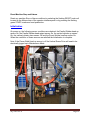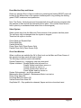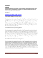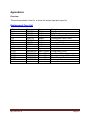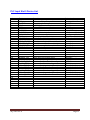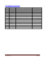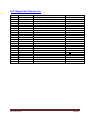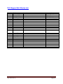
1
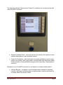
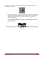
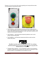
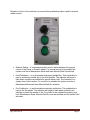
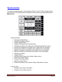
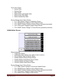
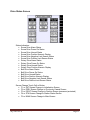
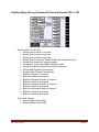
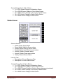
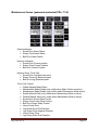
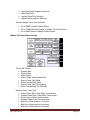
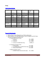
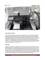
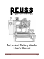
Automated Battery Welder
User’s Manual
AQ7140 rev. A Page 1 Introduction
This manual provides information to setup and operate the Automated Battery Welder.
The following is a series of sections that describe in detail each machine component
and its operation.
About The Machine
The Automated Battery Welder is a PLC controlled three axis electric driven positioning
machine. Its design allows for the automatic positioning of a battery to be welded by a
MIYACHI welder that has been integrated into this system. As a complete unit this
machine produces precisely positioned welds in a safe and efficient manner.
Theory of Operation
The battery to be welded is manually loaded onto the machine. After the cycle is started
the battery is positioned under one of two welder heads. There are three or six weld
positions under the pincer welder head and two weld positions under the parallel welder
head. Upon completion of the cycle the battery is manually removed from the machine.
AQ7140 rev. A Page 2 Table of Contents
Description outlines the design of the system. This section describes the Automated
Battery Welding Machine and includes definitions of all hardware and controls.
System
MCP Enclosure
Operator Interface
Page
5
5
10-17
Setup describes the machine adjustments and procedures.
Initial Settings
General Adjustments
18
18
Operation explains the basic operating sequence of the system.
Startup
Initialization
Modes of Operation
Shutdown
Weld Sequence of Operation
Tip Clean Sequence of Operation
19
20
22-25
25
27-38
41-47
Diagnostics defines system error indicators generated by the system.
Proximity Sensors
48
Appendices include fuse, and device lists.
Replacement Fuse List
PLC Input Device List
PLC Output Device List
PLC Stepper Device List
AQ7140 rev. A 50
51
52
53-54
Page 3 Safety Requirements
To avoid possible injury, and to operate the equipment in a safe and efficient manner,
please observe the following safety measures.
Do not operate any of the system components before they are installed.
Verify the proper tooling is installed and setup is complete.
Any unauthorized modifications to the control circuitry or other parts of the
system could cause damage to the equipment and / or injury to the operator.
Unauthorized modifications may also void the equipment warranty.
Do not operate this equipment with its cover(s) / guards off. If it becomes
necessary to remove the equipment cover(s) / guards, first turn off power at disconnect
and follow company lock-out procedures.
Do not operate this equipment without an equipment grounding connection.
Other safety requirements are included in this manual where they apply.
AQ7140 rev. A Page 4 Description
System
Line Voltage, MCP only (cord and plug connected) 120Vac, 1Phase, 60Hertz, 20Amp
Supply Air Pressure
100psi,
Regulated Air Pressure
80psi,
Control Voltage
24Vdc,
MCP Enclosure
The main control panel is located of the left side of the machine.
Mounted inside the MCP enclosure are the following components.
•
•
•
•
•
•
•
•
•
•
•
Automation Direct PLC
Sprecher+Schuh Load Switch
Automation Direct Relays
Automation Direct misc. terminal blocks
Automation Direct 5mm x 20mm fuse holders
Bussmann midget fuse holders
Safemaster E Stop Relay
RHINO Industrial DC Power Supply
Allen Bradley Solid State Relay
Oriental Motor Linear Motion Controller
Oriental Motor Hollow Rotary Actuator Driver
AQ7140 rev. A Page 5 The Operator Interface Panel and the “Power On” pushbutton is mounted on the right
side of the MCP enclosure.
•
Operator Interface Panel – is a touch screen to be used by the operator to view
machine status and to control machine function.
•
Power On Pushbutton – blue illuminated momentary pushbutton used to apply
power to the system. With supply power connected and main disconnect switch
closed operation of this pushbutton energizes the E-stop relay. Output power is
turned on.
Mounted on top of the MCP enclosure is a red beacon to indicate machine status.
•
Indicator Beacon – red beacon is not illuminated when machine is operating
normally, red beacon is flashing when a machine alarm is active, red beacon is
on steady when Stop Mode is active.
AQ7140 rev. A Page 6 Mounted on the top right corner of the MCP enclosure door is the main disconnect
switch operator handle.
•
Main Disconnect Switch – yellow and red rotary operator handle connected to the
main disconnect switch provides the ability to lock out power in the off (rotated
counter clockwise) position. When turned on (rotated clockwise) power is
supplied to the system.
Note: The MIYACHI Welder is connected to a separate power source and
disconnect switch.
Enclosure should not be opened before turning off power and disconnecting
power plug.
AQ7140 rev. A Page 7 Mounted on the top front side of the machine guarding are a three pushbutton station
and an emergency stop pushbutton station.
•
Start Pushbutton – green illuminated momentary mushroom head pushbutton
used to reset initialization alarms, reset drive alarms, reset machine alarms, reset
machine Stop Mode, initiate machine start of cycle, and advance machine control
sequence one step while in Step Mode.
•
Step Pushbutton – yellow illuminated maintained pushbutton used to active
machine sequence Step Mode.
•
Stop Pushbutton – red illuminated maintained pushbutton used to activate
machine Stop Mode.
Stop Mode is not the same as an EMERGENCY STOP. It is a software
controlled operation pause. Personnel should not work on any part of the
machine while it is in Stop Mode.
•
Emergency Stop Pushbutton – red non-illuminated mushroom head maintained
pushbutton. When this button is pressed the E-stop relay is de-energized, output
power is turned off. This pushbutton must be pulled out to reset.
AQ7140 rev. A Page 8 Mounted on front of the machine is a second three pushbutton station used for manual
welder control.
•
Selector Switch – is a maintained switch used to select between the manual
control of the Pincer or Parallel welder. For manual control to be enabled the
system must be in Maintenance Mode and have Manual Weld On selected.
•
Hold Pushbutton – is an illuminated maintained pushbutton. This pushbutton is
used to actuate the welder tips to the hold position. The indicator will begin to
flash when conditions are satisfied to permit welder Hold. The indicator is on
steady when Hold is active. For control to be enabled the system must be in
Maintenance Mode and have Manual Weld On selected.
•
Fire Pushbutton – is an illuminated momentary pushbutton. This pushbutton is
used to fire the welder. The indicator will begin to flash when conditions are
satisfied to permit the welder to fire. For control to be enabled the system must
be in Maintenance Mode, Manual Weld On must be selected and the welder Hold
activated.
AQ7140 rev. A Page 9 Operator Interface
The operator interface panel is an Automation Direct C-more 6” Micro-Graphic Panel
(touch screen).The following are the display screens with corresponding descriptions.
Main Screen
Status Indicators
• Emergency Stop Status
• Machine Initialization Status
• Welder Bypass Status
• Single or Double Pincer Weld Selection
• Maintenance Mode (only visible when Maintenance Mode is active)
• Screw Drive Negative Limit Status (only visible if limit is activated)
• Screw Drive Positive Limit Status (only visible if limit is activated)
• Belt Drive Negative Limit Status (only visible if limit is activated)
• Belt Drive Positive Limit Status (only visible if limit is activated)
• Safety Door Status
• Flapper Status
• Machine Alarm Status (only visible if alarm active)
• Screw Drive Alarm Status
• Rotary Drive Alarm Status
• Belt Drive Alarm Status
• Station Stop Status (only visible if Station Stop Mode is active)
Look Up Text:
• Displays active alarm description
• Displays current Style selected
AQ7140 rev. A Page 10 Touch Cell Control:
• System Start
• System Stop
• Alarm Reset
• Select Pincer and Parallel Weld
• Select Pincer Only Weld
• Select Parallel Only Weld
Screen Change Touch Cell or Button:
• F1 or INIT Screen Change to Initialization Screen
• F2 or DRIVE Screen Change to Drive Status Screen
• F3 or POSIT Screen Change to Position Screen (password protected)
• F4 or STA Screen Change to Station Status Screen
• F5 or MAINT Screen Change To Control Screen (password protected)
Initialization Screen
Status Indicators:
• Initialization Status
• Initialization Alarm Status (only visible if alarm is active)
• Pincer Welder Head Up Sensor Status
• Parallel Welder Head Up Sensor Status
• Parallel Welder Head Retract Sensor Status
• Vertical Cylinder Up Sensor Status
• Vertical Cylinder Down Sensor Status
Screen Change Touch Cell or Button:
• F1 or PREV Screen Change to Previously Viewed Screen
• F2 or DRIVE Screen Change to Drive Status Screen
• F3 or POSIT Screen Change to Position Screen (password protected)
• F4 or STA Screen Change to Station Status Screen
• F5 or MAIN Screen Change to Main Screen
AQ7140 rev. A Page 11 Drive Status Screen
Status Indicators:
• Screw Drive Alarm Status
• Screw Drive Power On Status
• Screw Drive Homed Status
• Screw Drive Position Numeric Display
• Screw Drive Negative Limit Sensor Status
• Screw Drive Positive Limit Sensor Status
• Rotary Drive Alarm Status
• Rotary Drive Power On Status
• Rotary Drive Homed Status
• Rotary Drive Position Numeric Display
• Belt Drive Alarm Status
• Belt Drive Power On Status
• Belt Drive Homed Status
• Belt Drive Position Numeric Display
• Belt Drive Negative Limit Sensor Status
• Belt Drive Positive Limit Sensor Status
Screen Change Touch Cell or Button:
• F1 or INIT Screen Change to Initialization Screen
• F2 or PREV Screen Change to Previously Viewed Screen
• F3 or POSIT Screen Change to Position Screen (password protected)
• F4 or STA Screen Change to Station Status Screen
• F5 or MAIN Screen Change to Main Screen
AQ7140 rev. A Page 12 Position Entry Screen (Password Protected Screen) PW = 7140
Numeric Entry Touch Cells:
• Rotary Drive Position 1 set point
• Rotary Drive Position 2 set point
• Rotary Drive Position 3 set point
• Rotary Drive Position for Parallel Weld Only Position set point
• Screw Drive Clear Up Position set point
• Screw Drive Top Pincer Weld Position set point
• Screw Drive Bottom Pincer Weld Position set point
• Pincer Weld Duration Timer preset
• Parallel Weld Duration Timer preset
• Belt Drive Position 1 set point
• Belt Drive Position 2 set point
• Belt Drive Reverse Position 2 set point
• Belt Drive Position 3 set point
• Belt Drive Reverse Position 3 set point
• Belt Drive Position 4 set point
• Belt Drive Reverse Position 4 set point
• Belt Drive Position 5 set point
• Belt Drive Position 6 set point
Touch Cell Control:
• Select Single Pincer Weld
• Select Double Pincer Weld
AQ7140 rev. A Page 13 Screen Change Touch Cell or Button:
• F1 or INIT Screen Change to Initialization Screen
• F2 or DRIVE Screen Change to Drive Status Screen
• F3 or PREV Screen Change to Previously Viewed Screen
• F4 or STA Screen Change to Station Status Screen
• F5 or MAIN Screen Change to Main Screen
Station Screen
Status Indicators:
• Welder Ready Signal Status
• Pincer Welder Head Up Sensor status
• Parallel Welder Head Up sensor status
• Parallel Welder Head Retract sensor status
• Vertical Cylinder Up sensor status
• Vertical Cylinder Down sensor status
• Battery Present Sensor Status
Look Up Text:
• Description of Current Sequence Step
• Description of Current Station Alarm
Screen Change Touch Cell or Button:
• F1 or INIT Screen Change to Initialization Screen
• F2 or DRIVE Screen Change to Drive Status Screen
• F3 or POSIT Screen Change to Position Screen (password protected)
• F4 or PREV Screen Change to Previously Viewed Screen
• F5 or MAIN Screen Change to Main Screen
AQ7140 rev. A Page 14 Maintenance Screen (password protected) PW = 7140
Status Indicators:
• Screw Drive Alarm Status
• Rotary Drive Alarm Status
• Belt Drive Alarm Status
Numeric Indicators:
• Screw Drive Current position
• Rotary Drive Current Position
• Belt drive Current Position
Numeric Entry Touch Cell:
• Screw Drive Jog Speed set point
• Rotary Drive Jog Speed set point
• Belt Drive Jog Speed set point
Touch Cell Control:
• Welder Bypass Mode Select
• Maintenance Mode Enable (only visible when Maint. Mode not active)
• Maintenance Mode Disable (only visible when Maintenance Mode active)
• Enable Manual Weld (only visible when Maintenance Mode is active)
• Disable Manual Weld (only visible when Maintenance Mode is active)
• Screw Drive Power Relay Control
• Rotary Drive Power Relay Control
• Belt Drive Power Relay Control
• Home Screw Drive
• Jog Screw Drive Plus Direction
• Jog Screw Drive Negative Direction
• Home Rotary Drive
• Jog Rotary Drive Plus Direction
AQ7140 rev. A Page 15 •
•
•
•
Jog Rotary Drive Negative Direction
Home Belt Drive
Jog Belt Drive Plus Direction
Jog Belt Drive Negative Direction
Screen Change Touch Cell or Button:
•
•
•
F2 or RESET used for Alarm Reset
F3 or CLEAN Screen Change to Welder Tip Clean Screen
F4 or MAIN Screen Change to Main Screen
Welder Tip Clean Status Screen
Touch Cell Control:
• System Start
• System Stop
• Alarm Reset
• Select Pincer and Parallel Weld
• Select Pincer Only Weld
• Select Parallel Only Weld
• Select Pincer Only Tip Cleaning
• Select Parallel Only Tip Cleaning
Numeric Entry Touch Cell:
• Pincer Clean Start / Stop Delay Timer preset
• Parallel Clean Start / Stop Delay Timer preset
• Pincer Clean Cycle Counter preset
• Parallel Clean Cycle Counter preset
• Belt Drive Clean position 1 set point
• Belt Drive Clean position 2 set point
• Belt Drive Clean position 5 set point
AQ7140 rev. A Page 16 •
•
•
Belt Drive Clean position 6 set point
Screw Drive Clean Top position set point
Screw Drive Clean Bottom position set point
Screen Change Touch Cell or Button:
•
•
F2 or PREV Screen Change to Previously Viewed Screen
F4 or MAIN Screen Change to Main Screen
AQ7140 rev. A Page 17 Setup
Initial Position Settings
Rotary Drive
Position 1
Position 2
Position 3
4,500
9,000
13,500
Screw Drive
Clear
Position
4,700
Top Weld
Position
7,598
Bottom Weld
Position
8,139
Belt Drive
Position 1
13,495
Position 2
13,642
Position 3
13,642
Position 4
13,642
Position 5
15,758
Reverse
Position 2
13,495
Reverse
Position 3
13,495
Reverse
Position 4
13,495
Position 6
Belt Drive
Position 3
Parallel
Only
-4,500
18,838
General Adjustments
1. Refer to Miyachi User’s Manual for any Welder adjustments.
2. Drive Positions – All of the Weld Positions may be changed from the Position
Screen of the Operator Interface Panel.
a. Rotary Drive Position Limits
i. Position 1
0 to 18,000
ii. Position 2
0 to 18,000
iii. Position 3
0 to 18,000
iv. Position 3 (Parallel weld only)
-18,000 to 0
b. Screw Drive Position Limits
i. Clear Position
0 to 9,800
ii. Top Weld Position (double Pincer only) 0 to 9,800
iii. Bottom Weld Position
0 to 9,800
c. Belt Drive Position Limits
i. All Belt Positions Limits are the same
AQ7140 rev. A 0 to 19,000
Page 18 Operation
Overview
The Automated Battery Welder has been designed for ease of use by employing
software that controls the operation and cycle of the machine. This reduces time for
setup and the possibility of problems. Each Weld cycle requires a battery to be manually
loaded and unloaded.
This section will cover the sequence of operation of the machine from power up to a
complete shutdown.
Startup
Caution: Before proceeding with the machine power up ensure that machine is
clear of personnel and that all affected personnel are notified.
Pre Power up Check
Check that the main disconnect switch is off.
Check that all safety guarding, flapper and door are in position and secure. Release the
red Stop pushbutton.
Powering On the Machine
Open air supply valve to machine (min. 80 psi.).
Plug power cord securely into properly rated outlet (min.120vac 15amp).
Turn on main disconnect switch located on the main control panel (rotate switch handle
clockwise). The processor will now have power and the program will start.
Turn on the Miyachi Welder (Supply power source disconnect is separate from the
automation power source, Welder power switch is located in rear of unit)
Pull emergency stop mushroom head pushbutton out.
Note: Before pressing blue Power On pushbutton check position of Horizontal
Belt Drive. Drive nest should be located off of the home sensor in the direction of
the welders. Manually move Drive if needed.
Press the blue Power On pushbutton located on the main control panel. Output power
will now be supplied to the machine and the blue Power On pushbutton indicator will
light.
AQ7140 rev. A Page 19 Reset Machine Stop and Alarms
Reset any machine Stop or Alarm conditions by selecting the flashing RESET touch cell
located on the Main screen of the operator interface panel or by pressing the flashing
green START mushroom head pushbutton.
Initialization
On power up, the following sensor conditions are checked: the Parallel Welder head up
sensor On, the Parallel Welder head retract sensor On, the vertical cylinder up sensor
On, the vertical cylinder down sensor Off and the Pincer Welder head up sensor On.
When the conditions of these sensors are satisfied the Initialization is complete.
Note: if the Pincer Weld Head up sensor is off the Vertical Screw Drive will need to be
electrically jogged up in Maintenance Mode.
AQ7140 rev. A Page 20 Reset Machine Stop and Alarms
Reset any machine Stop or Alarm conditions by selecting the flashing RESET touch cell
located on the Main screen of the operator interface panel or by pressing the flashing
green START mushroom head pushbutton.
Note: The Rotary, Vertical screw and Horizontal belt drives will become energized after
the machine is reset and will be electrically held in place. (The Vertical Screw drive is
held in place by a mechanical brake when drive is de-energized).
Select System
Select system style from the Main and Clean screens of the operator interface panel.
The style may only be changed when the system is stopped.
There are five styles to choose:
Pincer Weld and Parallel Weld
Pincer Weld Only
Parallel Weld Only
Pincer Clean Only (Clean Screen Only)
Parallel Clean Only (Clean Screen Only)
Ok to Start Machine
When conditions are satisfied the OK to Start touch on the Main and Clean Screen of
the operator interface panel will begin to flash.
The following conditions need to be satisfied:
System Powered Up – emergency stop relay energized
System Initialized – Parallel Welder head up sensor on
Parallel Welder head retract sensor on
Vertical cylinder up sensor on
Vertical cylinder down sensor off
Pincer Welder head up sensor on
System Style selected – any Style selected
Maintenance Mode Disabled – Maintenance Mode is not active
Rotary Drive Alarm Off
Horizontal Belt Drive Alarm Off
Vertical Screw Drive Alarm Off
Stop Mode Off – Stop pushbutton released, flapper and door closed and reset
AQ7140 rev. A Page 21 (The next operation motion will occur!)
Start System
To Start the system select the flashing OK to Start touch cell located on the Main screen
of the operator interface panel. The drive homing sequences will begin.
Drive Homing Sequence
Vertical Screw Drive will begin homing as soon as the system is started.
Rotary Drive will begin homing after the:
Parallel Welder head up sensor is on
Parallel Welder head retract sensor is on
Vertical cylinder up sensor is on
Vertical cylinder down sensor is off
Pincer Welder head up sensor is on
Horizontal Belt Drive will begin homing after the:
Parallel Welder head up sensor is on
Parallel Welder head retract sensor is on
Vertical cylinder up sensor is on
Vertical cylinder down sensor is off
Pincer Welder head up sensor is on
Rotary Drive is homed.
Modes of Operation
Cycle Run Weld Mode
Cycle Run Weld Mode can be enabled by selecting any of the three weld styles and
then by placing a battery on the battery nest and pressing the illuminated green Start
mushroom head pushbutton located at the pushbutton station. In Cycle Run Weld Mode
the machine is cycled and the battery is positioned to each of the set positions. After the
cycle is complete the battery is returned to the load position awaiting removal. The
battery present sensor on the nest must detect the battery being removed and another
battery being loaded (present) before another cycle is permitted to be started. The
illuminated green Start mushroom head pushbutton will need to be pushed to start a
new cycle.
AQ7140 rev. A Page 22 Battery
Present
Sensor
Battery Nest
Cycle Run Clean Mode
Cycle Run Clean Mode can be enabled by selecting any of the two tip cleaning styles,
then by placing the cleaning fixture on the battery nest and pressing the illuminated
green Start mushroom head pushbutton located at the pushbutton station. In Cycle Run
Clean Mode the machine is cycled and the cleaning fixture is positioned to each of the
set positions. After the cycle is complete the cleaning fixture is returned to the load
position. The cleaning fixture does not need to be removed from the battery nest before
a new cycle is restarted. The illuminated green Start mushroom head pushbutton will
need to be pushed to start a new cycle.
Stop Mode
Stop Mode is activated by pressing the red Stop pushbutton at the pushbutton station,
activating the flapper, opening the front safety door or by activating any of the drive over
travel limit switches. In Stop Mode the machine will stop all motion and all drive power
will be turned off. To deactivate Stop Mode if the Stop pushbutton was pressed, release
pushbutton, if the flapper was activated ensure it is returned to its proper position and if
the front safety door was opened close the door and then press the green flashing Start
mushroom head pushbutton. The drive homing sequence will then begin.
AQ7140 rev. A Page 23 System Stop Mode
System Stop Mode can be activated by pressing the STOP SYSTEM touch cell located
on the Main screen of the operator interface panel. In System Stop Mode the machine
will stop all motion although the drive power will remain on. To deactivate System Stop
Mode select the flashing Ok to Start touch cell located on the Main screen of the
operator interface panel. The drive homing sequence will then begin.
NOTE: If the Run cycle is in progress when Stop Mode is activated the current cycle is
aborted and the cycle will need to be restarted.
Machine Stop Mode is not the same as EMERGENCY STOP. It is a software
controlled operation pause. Personnel should not work on any part of the
machine while it is in Stop Mode.
Step Mode
Step Mode can be enabled by pressing the yellow Step maintained pushbutton located
at the pushbutton station. In Step Mode the machine cycle is stepped through each
operation. The flashing green Start mushroom head pushbutton located at the
pushbutton station is used to advance to the next step, the green Start mushroom head
pushbutton must be released then pressed again after the completion of each sequence
step. To disable Step Mode release the illuminated yellow Step pushbutton at any time.
Maintenance Mode
The Maintenance Mode function can only be enabled while in System Stop Mode. To
enable Maintenance Mode select the MAINT touch cell or F5 key from the Main screen
on the operator interface panel.(Maintenance Mode is password protected 7140).
Then select the ENABLE MAINT MODE touch cell on the Maintenance screen of the
operator interface panel. In Maintenance Mode each of the drives can be moved with
the various control touch cells. Maintenance Mode must be disabled before Cycle Run
Mode can be started. To disable Maintenance Mode from the Maintenance Screen of
the operator interface panel select DISABLE MAINT MODE touch cell.
Caution should be used when manually moving drive.
AQ7140 rev. A Page 24 Manual Weld Mode
The Manual Weld Mode function can only be enabled while Maintenance Mode is on.
To enable Manual Weld Mode first enable Maintenance Mode (see Maintenance Mode)
then from the Maintenance Screen on the operator interface panel select ENABLE
MANUAL WELD touch cell. The touch cell will then display MANUAL WELD ON. With
the Manual Weld Mode on the manual weld three button control station is now enabled.
The selector switch is used to select between manual control of the PINCER and
PARALLEL weld heads, the green HOLD maintained pushbutton will begin to flash.
Depressing the HOLD pushbutton will move the selected welder head tips to the weld
hold position without firing the welder, the HOLD indicator will be on steady and the
green FIRE pushbutton indicator will begin to flash. Pressing the FIRE momentary
pushbutton will fire the selected welder. To disable Manual Weld Mode from the
Maintenance Screen of the operator interface panel select DISABLE MANUAL WELD
touch cell. The Manual Weld touch cells are only visible when Maintenance Mode is on.
Caution should be used when manually welding.
Shutdown
Emergency Shutdown
There is one Emergency Stop mushroom head pushbutton on this machine and it is
located at the battery load side of the machine. Output power to the machine is turned
off immediately when the Emergency Stop mushroom head pushbutton is pressed.
Normal Shutdown
To have a normal controlled shutdown wait until the machine has completed its cycle.
Next press the red Stop pushbutton to enable Stop Mode. Then press the machine
Emergency Stop pushbutton. This will turn off all output power. Turn off the Miyachi
welder and then turn off main disconnect switch located on the main control panel
(rotate switch handle counter clockwise). Close the main air supply valve.
If maintenance is being performed on the machine unplug the power cord and
disconnect air supply.
Personnel should NOT work on any part of the machine
With power or air is applied.
AQ7140 rev. A Page 25 STYLE Selection
This Machine has the capability to run five different styles of operation. There are three
weld styles that can be selected from the Main of Clean screens of the operator
interface panel and there are two tip clean styles that can be selected from the Clean
screen of the operator interface panel. Style changes can only be made when the
system is stopped.
Style 1 PINCER and PARALLEL - The machine will perform the Pincer Weld and
Parallel Weld operations in one cycle.
Style 2 PINCER ONLY – The machine will only perform the Pincer Weld operation in
one cycle.
Style 3 Parallel Only – The machine will only perform the Parallel Weld operation in one
cycle.
Style 4 Pincer Clean Only – The machine will perform an automated Pincer tip cleaning
operation for the set number of cycles. The Pincer Clean cycle is the up and down
motion of the Vertical Screw Drive with the Pincer tips closed on the cleaning fixture.
Style 5 Parallel Clean Only – The machine will perform an automated Parallel tip
cleaning operation for the set number of cycles. The Parallel Clean cycle is the in and
out motion of the Horizontal Belt Drive with the Parallel tips closed on the cleaning
fixture.
Pincer Weld Selection
There are two variations for the number of times the Pincer Weld is activated per
position. The selection change can be from the password protected Position Entry
screen of the operator interface panel (password 7140). The selection change can only
be made when the system is stopped.
Single Pincer Weld – The Pincer Welder is only activated once per position. The Pincer
Welder is activated a total of three times per cycle.
Double Pincer Weld – The Pincer Welder is activated twice per position. The distance
between the welds can be adjusted from the Position Entry screen of the operator
interface panel. The Pincer Welder is activated a total of six times per cycle.
AQ7140 rev. A Page 26 Weld Sequence of Operation
The following is a step by step description of the sequence of operation of the machine.
Note: PLC Address reference in parenthesis ( ).
If any of the step conditions are not met the machine will fault. The red beacon located
on top of the main control panel, the green Start mushroom head pushbutton indicator
and the Reset touch cell located on the main screen of the operator interface panel will
begin to flash. The corresponding alarm message will be displayed on the look up text
box on the Main and Station screens of the operator interface panel. Pressing the green
Start pushbutton or flashing Reset touch cell will reset the machine fault and retry the
same step.
Step 0
Check Home Wait WORK On
Check Pincer Welder head up sensor is on (X6).
Check Parallel Welder head up sensor is on (X7).
Check Parallel Welder head retract sensor is on (X12).
Check Vertical Cylinder up sensor is on (X16).
Check Vertical Cylinder down sensor is off (X17)
Check Rotary drive is home.
Check Horizontal Belt drive is home.
Check Vertical Screw drive is home or style "Parallel Only" is selected.
After a delay if condition not met, alarm message "Check Home Sensors and
Positions" will be displayed
Step 0
Set Welder Schedule Selection
Wait Battery Loaded to Nest and green Start Mushroom Head
pushbutton pressed
Wait battery present sensor on (X5).
Wait illuminated green Start mushroom head pushbutton (X4) to be pressed.
Welder Schedule Selection:
Turn off Welder Schedule Bit 0 (Y1)
Turn on Welder Schedule Bit 1 (Y2)
Step 1
Check Style
If style Parallel Only is not selected continue to Step 2.
If style Parallel Only is selected go to Step 25.
AQ7140 rev. A Page 27 Step 2
Move Horizontal Belt in to Position 1 and Wait,
Set Welder Schedule Selection
Move Horizontal Belt in to Position 1
Wait for Horizontal Belt drive at Position 1.
After a delay if condition not met, alarm message "Horz Belt Not at Position 1"
will be displayed
Welder Schedule Selection:
Turn on Welder Schedule Bit 0 (Y1)
Turn off Welder Schedule Bit 1 (Y2)
Step 3
Move Vertical Screw to bottom Pincer Weld Position and Wait
Move Vertical Screw down to bottom Pincer Weld Position
Wait for Vertical Screw at bottom Pincer Weld Position.
After a delay if condition not met, alarm message "Vert Screw Not at Btm Pincer
Weld Position" will be displayed
Step 4
Move Horizontal Belt in to Position 2 and Wait
Move Horizontal Belt in to Position 2
Wait for Horizontal Belt at Position 2
After a delay if condition not met, alarm message "Horz Belt Not at Position 2"
will be displayed
Step 5
Turn on Welder and Check Ready Signal Off
Turn on Welder Hold relay (Y12)
Turn on Welder Fire relay (Y3)
Check Welder Ready Signal is Off (X11)
After a delay if condition not met, alarm message "Welder Ready Signal Still On"
will be displayed
AQ7140 rev. A Page 28 Step 6
Wait Welder Ready Signal On
Wait for Welder Ready Signal to be On (X11)
After a delay if condition not met, alarm message "Welder Ready Signal Did Not
Activate" will be displayed
Step 7
Continue to next Step or Return for second Weld
When Double Pincer Weld is selected:
After first Pincer Weld, Move Vertical Screw up to Top Pincer
Weld Position
Wait for Vertical Screw at Top Pincer Weld Position.
If Double Pincer Weld is selected: After first Pincer Weld Return to Step 5 for
second weld.
After second Pincer weld Move Horizontal Belt out to Reverse Position 2
Wait for Horizontal Belt at Reverse Position 2
When Single Pincer Weld is selected:
After first Pincer Weld, Move Horizontal Belt out to Reverse Position 2
Wait for Horizontal Belt at Reverse Position 2
If Single Pincer Weld is selected: After first Pincer Weld continue to Step 8
After a delay if condition not met, alarm message "Horz Belt Not at Reverse
Position 2 or Vert Screw Not at Top Pincer Weld Position" will be displayed
Step 8
Move Vertical Screw to Clear Position and Check Sensor
Move Vertical Screw up to Clear Position
Wait for Vertical Screw at Clear Position
Check Pincer Welder head up sensor On (X6)
After a delay if condition not met, alarm message "Vert Screw Not at Clear
Position or Pincer Welder Up Sensor Did Not Activate" will be displayed
AQ7140 rev. A Page 29 Step 9
Rotate Rotary clock-wise to Position 1 and Wait
Rotate Rotary clock-wise to Position 1
Wait Rotary at Position 1
After a delay if condition not met, alarm message "Rotary Not at Position 1" will
be displayed
Step 10
Move Vertical Screw to bottom Pincer Weld Position and Wait
Move Vertical Screw down to bottom Pincer Weld Position
Wait for Vertical Screw at bottom Pincer Weld Position
After a delay if condition not met, alarm message "Vert Screw Not at Btm Pincer
Weld Position" will be displayed
Step 11
Move Horizontal Belt in to Position 3 and Wait
Move Horizontal Belt in to Position 3
Wait for Horizontal Belt at Position 3
After a delay if condition not met, alarm message "Horz Belt Not at Position 3"
will be displayed
Step 12
Turn on Welder and Check Ready Signal Off
Turn on Welder Hold relay (Y12)
Turn on Welder Fire relay (Y3)
Check Welder Ready Signal is Off (X11)
After a delay if condition not met, alarm message "Welder Ready Signal Still On"
will be displayed
Step 13
Wait for Welder Ready Signal On
Wait for Welder Ready Signal to be On (X11)
After a delay if condition not met, alarm message "Welder Ready Signal Did Not
Activate" will be displayed
AQ7140 rev. A Page 30 Step 14
Continue to next Step or Return for second Weld
When Double Pincer Weld is selected:
After first Pincer Weld, Move Vertical Screw up to Top Pincer
Weld Position
Wait for Vertical Screw at Top Pincer Weld Position.
If Double Pincer Weld is selected: After first Pincer Weld Return to Step 12 for
second weld.
After second Pincer weld Move Horizontal Belt out to Reverse Position 3
Wait for Horizontal Belt at Reverse Position 3
When Single Pincer Weld is selected:
After first Pincer Weld, Move Horizontal Belt out to Reverse Position 3
Wait for Horizontal Belt at Reverse Position 3
If Single Pincer Weld is selected: After first Pincer Weld
Continue to Step 15
After a delay if condition not met, alarm message "Horz Belt Not at Reverse
Position 3 or Vert Screw Not at Top Pincer Weld Position" will be displayed
Step 15
Move Vertical Screw to Clear Position and Check Sensor
Move Vertical Screw up to Clear Position
Wait for Vertical Screw at Clear Position
Check Pincer Welder head up sensor On (X6)
After a delay if condition not met, alarm message "Vert Screw Not at Clear
Position or Pincer Welder Up Sensor Did Not Activate" will be displayed
Step 16
Rotate Rotary clock-wise to Position 2 and Wait
Rotate Rotary clock-wise to Position 2
Wait Rotary at Position 2
After a delay if condition not met, alarm message "Rotary Not at Position 2" will
be displayed
AQ7140 rev. A Page 31 Step 17
Move Vertical Screw to bottom Pincer Weld Position and Wait
Move Vertical Screw down to bottom Pincer Weld Position
Wait for Vertical Screw at bottom Pincer Weld Position
After a delay if condition not met, alarm message "Vert Screw Not at Btm Pincer
Weld Position" will be displayed
Step 18
Move Horizontal Belt in to Position 4 and Wait
Move Horizontal Belt in to Position 4
Wait for Horizontal Belt at Position 4
After a delay if condition not met, alarm message "Horz Belt Not at Position 4"
will be displayed
Step 19
Turn on Welder and Check Ready Signal Off
Turn on Welder Hold relay (Y12)
Turn on Welder Fire relay (Y3)
Check Welder Ready Signal is Off (X11)
After a delay if condition not met, alarm message "Welder Ready Signal Still On"
will be displayed
Step 20
Wait for Welder Ready Signal On
Wait for Welder Ready Signal to be On (X11)
After a delay if condition not met, alarm message "Welder Ready Signal Did Not
Activate" will be displayed
AQ7140 rev. A Page 32 Step 21
Continue to next Step or Return for second Weld
When Double Pincer Weld is selected:
After first Pincer Weld, Move Vertical Screw up to Top Pincer
Weld Position
Wait for Vertical Screw at Top Pincer Weld Position.
If Double Pincer Weld is selected: After first Pincer Weld Return to Step 19 for
second weld.
After second Pincer weld Move Horizontal Belt out to Reverse Position 4
Wait for Horizontal Belt at Reverse Position 4
When Single Pincer Weld is selected:
After first Pincer Weld, Move Horizontal Belt out to Reverse Position 4
Wait for Horizontal Belt at Reverse Position 4
If Single Pincer Weld is selected: After first Pincer Weld
Continue to Step 22
After a delay if condition not met, alarm message "Horz Belt Not at Reverse
Position 4 or Vert Screw Not at Top Pincer Weld Position" will be displayed
Step 22
Move Vertical Screw to Clear Position and Check Sensor
Move Vertical Screw up to Clear Position
Wait for Vertical Screw at Clear Position
Check Pincer Welder head up sensor On (X6)
After a delay if condition not met, alarm message "Vert Screw Not at Clear
Position or Pincer Welder Up Sensor Did Not Activate" will be displayed
AQ7140 rev. A Page 33 Step 23
Set Welder Schedule Selection
If style Pincer Only is selected Move Vertical Screw Home and
continue to Step 24
Move Vertical Screw up to Home Position
If style Pincer Only is not selected Move Vertical Screw Home,
Move Horizontal Belt in to Position 5, Rotate Rotary to Position
3 and Wait
Move Vertical Screw up to Home Position
Move Horizontal Belt in to Position 5
Move Rotary clock-wise to Position 3
Wait Rotary at Position 3
After a delay if condition not met, alarm message "Rotary Not at Position 3" will
be displayed
Wait Horizontal Belt at Position 5
After a delay if condition not met, alarm message "Horz Belt Not at Position 5 "
will be displayed
Welder Schedule Selection:
Turn off Welder Schedule Bit 0 (Y1)
Turn on Welder Schedule Bit 1 (Y2)
Step 24
If style Pincer and Parallel Weld is not selected go to Step 44
If style Pincer and Parallel Weld is selected Wait Horizontal
Belt at Position 5
Wait Horizontal Belt at Position 5
No alarm
AQ7140 rev. A Page 34 Step 25
If style Parallel Weld Only is not selected continue to Step 26
If style Parallel Weld Only is selected Move Horizontal Belt in
to Position 5 and Wait
If style Parallel Weld Only is selected:
Move Horizontal Belt in to Position 5
Wait for Horizontal Belt at Position 5
After a delay if condition not met, alarm message "Horz Belt Not at
Position 5" will be displayed
Step 26
If style Parallel Weld only is not selected continue to Step 27
If style Parallel Weld Only is selected Rotate Rotary counter
clockwise to Position 3 and Wait
Rotate Rotary counter-clockwise to Position 3
Wait Rotary at Position 3
After a delay if condition not met, alarm message "Rotary Not at
Position 3 "will be displayed
Step 27
Lower Vertical Cylinder and Check Vertical Up Sensor
Turn on solenoid (Y13)
Check Vertical Up sensor Off (X16)
After a delay if condition not met, alarm message "Vertical Cylinder Up Sensor
Still On" will be displayed
Step 28
Check Vertical Cylinder Down Sensor
Check Vertical Down sensor On (X17)
After a delay if condition not met, alarm message "Vertical Cylinder Down Sensor
Did Not Activate" will be displayed
AQ7140 rev. A Page 35 Step 29
Turn on Welder and Check Ready Signal Off
Turn on Welder Hold relay (Y12)
Turn on Welder Fire relay (Y3)
Check Welder Ready Signal to be Off (X11)
After a delay if condition not met, alarm message "Welder Ready Signal Still On"
will be displayed
Step 30
Wait for Welder Ready Signal On and Check Sensors
Wait for Welder Ready Signal to be On (X11)
Check Parallel Welder head up sensor On (X7)
Check Parallel Welder head retract sensor On (12)
After a delay if condition not met, alarm message "Welder Ready Signal or
Parallel Welder Up Sensor or Parallel Welder Retract Sensor Did Not Activate"
will be displayed
Step 31
Move Horizontal Belt in to Position 5A
Wait for Horz Belt at Position 5A
After a delay if condition is not met, alarm message “Horz Belt Not at Positon 5A”
will be displayed
Step 32
Turn on Welder and Check Ready Signal Off
Turn on Welder Hold relay (Y12)
Turn on Welder Fire relay (Y3)
Check Welder Ready Signal to be Off (X11)
After a delay if condition not met, alarm message "Welder Ready Signal Still On"
will be displayed
AQ7140 rev. A Page 36 Step 33
Wait for Welder Ready Signal On and Check Sensors
Wait for Welder Ready Signal to be On (X11)
Check Parallel Welder head up sensor On (X7)
Check Parallel Welder head retract sensor On (12)
After a delay if condition not met, alarm message "Welder Ready Signal or
Parallel Welder Up Sensor or Parallel Welder Retract Sensor Did Not Activate"
will be displayed
Step 34
Raise Vertical Cylinder and Check Vertical Up Sensor
Turn off solenoid (Y13)
Check Vertical Cylinder Up sensor On (X16)
After a delay if condition not met, alarm message "Vertical Cylinder Up Sensor
Did Not Activate" will be displayed
Step 35
Move Horizontal Belt in to Position 6
Wait for Horz Belt at Position 6
After a delay if condition not met, alarm message "Horz Belt Not at Position 6"
will be displayed
Step 36
Lower Vertical Cylinder and Check Vertical Up Sensor
Turn on solenoid (Y13)
Check Vertical Up sensor Off (X16)
After a delay if condition not met, alarm message "Vertical Cylinder Up Sensor
Still On" will be displayed
Step 37
Check Vertical Cylinder Down Sensor
Check Vertical Down sensor On (X17)
After a delay if condition not met, alarm message "Vertical Cylinder Down Sensor
Did Not Activate" will be displayed
AQ7140 rev. A Page 37 Step 38
Turn on Welder and Check Ready Signal Off
Turn on Welder Hold relay (Y12)
Turn on Welder Fire relay (Y3)
Check Welder Ready Signal is Off (X11)
After a delay if condition not met, alarm message "Welder Ready Signal Still On"
will be displayed
Step 39
Wait for Welder Ready Signal On and Check Sensors
Wait for Welder Ready Signal to be On (X11)
Check Parallel Welder head up sensor On (X7)
Check Parallel Welder head retract sensor On (X12)
After a delay if condition not met, alarm message "Welder Ready Signal or
Parallel Welder Up Sensor or Parallel Welder Retract Sensor Did Not Activate"
will be displayed
Step 40
Move Horizontal Belt in to Position 6A
Wait for Horz Belt at Position 6A
After a delay if condition is not met, alarm message “Horz Belt Not at Positon 5A”
will be displayed
Step 41
Turn on Welder and Check Ready Signal Off
Turn on Welder Hold relay (Y12)
Turn on Welder Fire relay (Y3)
Check Welder Ready Signal is Off (X11)
After a delay if condition not met, alarm message "Welder Ready Signal Still On"
will be displayed
AQ7140 rev. A Page 38 Step 42
Wait for Welder Ready Signal On and Check Sensors
Wait for Welder Ready Signal to be On (X11)
Check Parallel Welder head up sensor On (X7)
Check Parallel Welder head retract sensor On (X12)
After a delay if condition not met, alarm message "Welder Ready Signal or
Parallel Welder Up Sensor or Parallel Welder Retract Sensor Did Not Activate"
will be displayed
Step 43
Raise Vertical Cylinder and Check Vertical Up Sensor
Turn off solenoid (Y13)
Check Vertical Cylinder Up sensor On (X16)
After a delay if condition not met, alarm message "Vertical Cylinder Up Sensor
Did Not Activate" will be displayed
Step 44
Rotate Rotary to Position 4 and Wait
Rotate Rotary to clock-wise to Position 4
Wait for Rotary at Position 4
After a delay if condition not met, alarm message "Rotary Not at Position 4" will
be displayed
Step 45
Rotate Rotary to Home Position and Wait
Rotate Rotary to Home Position
Wait for Rotary at Home Position
After a delay if condition not met, alarm message "Rotary Not at Home
Position" will be displayed
AQ7140 rev. A Page 39 Step 46
Move Horizontal Belt to Position 7 and Wait
Move Horizontal Belt out to Position 7
Wait for Horz Belt at Position 7
After a delay if condition not met, alarm message "Horz Belt Not at Position 7"
will be displayed
Step 47
Move Horizontal Belt to Home Position and Wait
Move Horizontal Belt out to Home Position
Wait Horizontal Belt at Home Position
After a delay if condition not met, alarm message "Horz Belt Not at Home
Position" will be displayed
Step 48
Wait Battery Removed from Nest
Check Battery Present Sensor Off (X5)
Step 49
Pulse Cycle Done and Wait
Pulse Done Bit on
Wait for Work Bit Off
Step 50
Restart
AQ7140 rev. A Page 40 Tip Clean Sequence of Operation
The following is a step by step description of the sequence of operation of the machine.
Note: PLC Address reference in parenthesis ( ).
If any of the step conditions are not met the machine will fault. The red beacon located
on top of the main control panel, the green Start mushroom head pushbutton indicator
and the Reset touch cell located on the main screen of the operator interface panel will
begin to flash. The corresponding alarm message will be displayed on the look up text
box on the Main and Station screens of the operator interface panel. Pressing the green
Start pushbutton or flashing Reset touch cell will reset the machine fault and retry the
same step.
Step 0
Check Home Wait WORK On
Check Pincer Welder head up sensor is on (X6).
Check Parallel Welder head up sensor is on (X7).
Check Parallel Welder head retract sensor is on (X12).
Check Vertical Cylinder up sensor is on (X16).
Check Vertical Cylinder down sensor is off (X17)
Check Rotary drive is home.
Check Horizontal Belt drive is home.
Check Vertical Screw drive is home or style "Parallel Only" is selected.
After a delay if condition not met, alarm message "Check Home Sensors and
Positions" will be displayed
Step 0
Set Welder Schedule Selection
Wait Cleaning Fixture Loaded to Nest and green Start Mushroom
Head pushbutton pressed
Wait battery present sensor on (X5).
Wait illuminated green Start mushroom head pushbutton (X4) to be pressed.
Welder Schedule Selection:
Turn off Welder Schedule Bit 0 (Y1)
Turn on Welder Schedule Bit 1 (Y2)
Step 1
Check Style
If style Clean Parallel Only is not selected continue to Step 2.
If style Clean Parallel Only is selected go to Step 16.
AQ7140 rev. A Page 41 Step 2
Move Horizontal Belt in to Position 1C and Wait,
Set Welder Schedule Selection
Move Horizontal Belt in to Position 1C
Wait for Horizontal Belt drive at Position 1C.
After a delay if condition not met, alarm message "Horz Belt Not at Position 1C"
will be displayed
Welder Schedule Selection:
Turn on Welder Schedule Bit 0 (Y1)
Turn off Welder Schedule Bit 1 (Y2)
Step 3
Move Vertical Screw to bottom Pincer Clean Position and Wait
Move Vertical Screw down to bottom Clean Position
Wait for Vertical Screw at bottom Clean Position.
After a delay if condition not met, alarm message "Vert Screw Not at Btm Clean
Position" will be displayed
Step 4
Move Horizontal Belt in to Position 2C and Wait
Move Horizontal Belt in to Position 2C
Wait for Horizontal Belt at Position 2C
After a delay if condition not met, alarm message "Horz Belt Not at Position 2C"
will be displayed
Step 5
Turn on Welder Hold and Wait Welder Hold
Turn on Welder Hold relay (Y12)
Wait Welder Hold relay On (Y12)
Step 6
Wait Start Delay
Wait Start Delay Timer Done to be On
AQ7140 rev. A Page 42 Step 7
Move Vertical Screw to Top Pincer Clean Position and Wait
Move Vertical Screw up to Top Clean Position
Wait for Vertical Screw at Top Clean Position
After a delay if condition not met, alarm message "Vert Screw Not at Top Clean
Position" will be displayed
Step 8
Move Vertical Screw to Bottom Pincer Clean Position and Wait
Move Vertical Screw up to Bottom Clean Position
Wait for Vertical Screw at Bottom Clean Position
After a delay if condition not met, alarm message "Vert Screw Not at Btm Clean
Position " will be displayed
Step 9
Increment Pincer Clean Cycle Counter 1 count and Check Done
Increment Pincer Cycle Counter by 1
Check if Pincer Cycle Counter done bit On
If Pincer Cycle Counter is not done Go To Step 7
If Pincer Cycle Counter is done Continue to Next Step 10
Step 10
Turn off Welder Hold and Wait Welder Hold
Turn off Welder Hold relay (Y12)
Wait Welder Hold relay Off (Y12)
Step 11
Wait Stop Delay
Wait Stop Delay Timer Done to be On
Step 12
Move Horizontal Belt out to Position 1C and Wait,
Move Horizontal Belt in to Position 1C
Wait for Horizontal Belt drive at Position 1C.
After a delay if condition not met, alarm message "Horz Belt Not at Position 1C"
will be displayed
AQ7140 rev. A Page 43 Step 13
Move Vertical Screw to Clear Position and Check Sensor
Move Vertical Screw up to Clear Position
Wait for Vertical Screw at Clear Position
Check Pincer Welder head up sensor On (X6)
After a delay if condition not met, alarm message "Vert Screw Not at Clear
Position or Pincer Welder Up Sensor Did Not Activate" will be displayed
Step 14
Move Vertical Screw Home and Wait
Move Vertical Screw to Home Position
Wait for Vertical Screw at Home Position
After a delay if condition not met, alarm message "Vert Screw Not at Home
Position" will be displayed
Welder Schedule Selection:
Turn off Welder Schedule Bit 0 (Y1)
Turn on Welder Schedule Bit 1 (Y2)
Step 15
Check Style
If style Clean Pincer Only is not selected continue to Step 16.
If style Clean Pincer Only is selected go to Step 27.
Step 16
Move Horizontal Belt in to Position 5C and Wait
Move Horizontal Belt in to Position 5C
Wait Horizontal Belt at Position 5C
After a delay if condition not met, alarm message "Horz Belt Not at Position 5C"
will be displayed
AQ7140 rev. A Page 44 Step 17
Lower Vertical Cylinder and Check Vertical Up Sensor
Turn on solenoid (Y13)
Check Vertical Up sensor Off (X16)
After a delay if condition not met, alarm message "Vertical Cylinder Up Sensor
Still On" will be displayed
Step 18
Check Vertical Cylinder Down Sensor
Check Vertical Down sensor On (X17)
After a delay if condition not met, alarm message "Vertical Cylinder Down Sensor
Did Not Activate" will be displayed
Step 19
Turn on Welder Hold and Wait Welder Hold and Sensor
Turn on Welder Hold relay (Y12)
Wait for Welder Hold relay On (Y12)
Wait for Parallel Welder head up sensor Off (X7)
Wait for Parallel Welder head retract sensor Off (X12)
Step 20
Wait Start Delay
Wait Start Delay Timer Done to be On
Step 21
Move Horizontal Belt in to Position 6C
Wait for Horz Belt at Position 6C
After a delay if condition not met, alarm message "Horz Belt Not at Position 6C"
will be displayed
Step 22
Move Horizontal Belt out to Position 5C and Wait
Move Horizontal Belt out to Position 5C
Wait Horizontal Belt at Position 5C
After a delay if condition not met, alarm message "Horz Belt Not at Position 5C"
will be displayed
AQ7140 rev. A Page 45 Step 23
Increment Parallel Clean Cycle Counter 1 count and Check Done
Increment Parallel Cycle Counter by 1
Check if Parallel Cycle Counter done bit On
If Parallel Cycle Counter is not done Go To Step 21
If Parallel Cycle Counter is done Continue to Next Step 24
Step 24
Turn off Welder Hold, Wait and Check Sensors
Turn off Welder Hold relay (Y12)
Wait for Welder Hold relay Off (Y12)
Check for Parallel Welder head up sensor Off (X7)
Check for Parallel Welder head retract sensor Off (X12)
After a delay if condition not met, alarm message "Parallel Up or Retract Sensors
Did Not Activate" will be displayed
Step 25
Wait Stop Delay
Wait Stop Delay Timer Done to be On
Step 26
Raise Vertical Cylinder and Check Vertical Up Sensor
Turn off solenoid (Y13)
Check Vertical Cylinder Up sensor On (X16)
After a delay if condition not met, alarm message "Vertical Cylinder Up Sensor
Did Not Activate" will be displayed
Step 27
Move Horizontal Belt to Position 7 and Wait
Move Horizontal Belt out to Position 7
Wait for Horz Belt at Position 7
After a delay if condition not met, alarm message "Horz Belt Not at Position 7"
will be displayed
AQ7140 rev. A Page 46 Step 28
Move Horizontal Belt to Home Position and Wait
Move Horizontal Belt out to Home Position
Wait Horizontal Belt at Home Position
After a delay if condition not met, alarm message "Horz Belt Not at Home
Position" will be displayed
Step 29
Pulse Cycle Done and Wait
Pulse Done Bit on
Wait for Work Bit Off
Step 30
Restart
AQ7140 rev. A Page 47 Diagnostics
Overview
This section identifies various faults and errors that are detected by the system. Error
conditions will be indicated with a message on the operator interface panel and red
beacon on top of the main control panel.
Conditions
Proximity and Photo Optic Sensors
Pincer Welder Head Up Proximity Sensor
At various steps in the operation the position of the Pincer welder head is checked to be
up. If the Pincer welder head is not in the up position when required the machine will
fault. The Reset touch cell located on the Main, Maintenance and Clean screens of the
Operator Interface panel, the green Start push button of the three button station and the
red Beacon located on top of the Main Control Panel will flash indicating a fault. A
corresponding alarm message will be displayed on the Main and Station screen of the
Operator Interface Panel. Pressing and Reset touch cell or the green Start push button
will reset the fault and retry the step.
Parallel Welder Head Up Proximity Sensor
At various steps in the operation the position of the Parallel welder head is checked to
be up. If the Parallel welder head is not in the up position when required the machine
will fault. The Reset touch cell located on the Main, Maintenance and Clean screens of
the Operator Interface panel, the green Start push button of the three button station and
the red Beacon located on top of the Main Control Panel will flash indicating a fault. A
corresponding alarm message will be displayed on the Main and Station screen of the
Operator Interface Panel. Pressing and Reset touch cell or the green Start push button
will reset the fault and retry the step.
Parallel Welder Head Retract Proximity Sensor
At various steps in the operation the position of the Parallel welder head is checked to
be retracted. If the Parallel welder head is not in the retract position when required the
machine will fault. The Reset touch cell located on the Main, Maintenance and Clean
screens of the Operator Interface panel, the green Start push button of the three button
station and the red Beacon located on top of the Main Control Panel will flash indicating
a fault. A corresponding alarm message will be displayed on the Main and Station
screen of the Operator Interface Panel. Pressing and Reset touch cell or the green Start
push button will reset the fault and retry the step.
AQ7140 rev. A Page 48 Parallel Welder Vertical Cylinder Proximity Sensor
At various steps in the operation the position of the Parallel welder vertical cylinder is
checked to be either up or down. If the Parallel welder vertical cylinder is not in the
correct position when required the machine will fault. The Reset touch cell located on
the Main, Maintenance and Clean screens of the Operator Interface panel, the green
Start push button of the three button station and the red Beacon located on top of the
Main Control Panel will flash indicating a fault. A corresponding alarm message will be
displayed on the Main and Station screen of the Operator Interface Panel. Pressing and
Reset touch cell or the green Start push button will reset the fault and retry the step.
Over-travel Limit Photo Optic Sensors
At each end of travel of the Vertical Screw Drive and Horizontal Belt Drive are overtravel limit sensors. If at any time an over-travel sensor is activated the associated drive
will stop motion and Stop Mode will be activated. The status of these sensors is
displayed on the Main and Drive Status screens.
Battery Present Photo Optic Sensor
Mounted to the battery nest is a battery present sensor. This sensor is used to permit
the start and end of each cycle. The sensor must be activated to permit the starting of a
cycle. In weld mode the sensor must be deactivated to permit the completion of the
cycle.
AQ7140 rev. A Page 49 Appendices
Overview
This section provides a fuse list, a device list and an input and output list.
Replacement Fuse List
AC Fuse Number
FU1
FU2
FU3
FU4
FU5
FU6
FU7
Edison
EDCC20
EDCC2
EDCC6
EDCC15
EDCC10
EDCC7
EDCC7
Type
Midget
Midget
Midget
Midget
Midget
Midget
Midget
Destination
Main Power Circuit
PLC Circuit
DC Power Supply Circuit
Convenience Outlet Circuit
Rotary Drive
Horizontal Belt Drive
Vertical Screw Drive
DC Fuse Number
FU1D1
FU2D1
FU3D1
FU4D1
FU5D1
Bussman
BK/GMA-2A
BK/GMA-2A
BK/GMA-2A
BK/GMA-2A
BK/GMA-2A
Type
5mm x 20mm
5mm x 20mm
5mm x 20mm
5mm x 20mm
5mm x 20mm
Destination
E-Stop Relay Circuit
Input Device Circuit
Operator Interface C-More Micro
Output Device Circuit
Drive Logic Circuit
AQ7140 rev. A Page 50 PLC Input Slot 0 Device List
Address
Tag Name
Description
X0
X1
X2
X3
X4
X5
X6
X7
X10
X11
X12
X13
X14
X15
X16
X17
ESR_4
FLAPPER
STOP
STEP
START
BATTPRES
PINCERUP
PARALLELUP
DOOR
WELDREADY
PARALLELRET
WELD_SELECT
WELDHOLD_PB
WELDFIRE_PB
VERTUP
VERTDN
Safemaster E Stop Relay LG5924-48-61-24
Hinge Safety Switch
Red STOP Maintained Pushbutton
Yellow STEP Maintained Pushbutton
Green START Momentary Pushbutton
Photo sensor
Pincer Weld Head Up Sensor
Parallel Weld Head Up Sensor
Non-locking Safety Door Switch
Welder Ready Signal Relay K2
Parallel Welder Head Retract Sensor
Weld Selector Switch 0=Pincer 1=Parallel
Green Maintained Pushbutton Weld Hold
Green Momentary Pushbutton Weld Fire
Parallel Vertical Cylinder Up Sensor
Parallel Vertical Cylinder Down Sensor
Device detail
[Welder Pin#] “Tag Name”
Normally Closed contact 4
SCHMERSAL
Normally closed contact
Normally open contact
Normally open contact
Keyence PZM-12
Auto Direct AE1-AN-AF
Auto Direct AE1-AN-AF
COMPEPI SP2K20W02
[6] “Run State” [13] “1000”
Auto Direct AE1-AN-AF
Normally open contact
Normally open contact
Normally open contact
QE-022-NS-11L
QE-022-NS-11L
X20
X21
X22
X23
X24
X25
X26
X27
X30
X31
X32
X33
X34
X35
X36
X37
ENDMOV_ROT
ALARM_ROT
ENDMOV_BELT
ALARM_BELT
NEGLIM_BELT
POSLIM_BELT
ENDMOV_SCREW
ALARM_SCREW
NEGLIM_SCREW
POSLIM_SCREW
Rotary Drive End of Move Signal
Rotary Drive Alarm Signal
Horizontal Belt Drive End of Move Signal
Horizontal Belt Drive Alarm Signal
Horizontal Belt Negative Over Travel Sensor
Horizontal Belt Positive Over Travel Sensor
Vertical Screw Drive End of Move Signal
Vertical Screw Drive Alarm Signal
Vertical Screw Negative Over Travel Sensor
Vertical Screw Positive Over Travel Sensor
[Drive Pin#] “Tag Name”
[29] “END”
[25] “ALARMOUT”
[4] “END”
[2] “ALM”
Omron PAD6-SB (n.c.)
Omron PAD6-SB (n.c.)
[4] “END”
[2] “ALM”
Omron PAD6-SB (n.c.)
Omron PAD6-SB (n.c.)
AQ7140 rev. A Page 51 PLC Output Slot 1 Device List
Address
Tag Name
Description
Device detail
[Welder Pin#] “Tag Name”
Y0
Y1
Y2
Y3
Y4
ALARMLA
WELD_SCHBIT0
WELD_SCHBIT1
WELD_FIRE
WELD_INHIBIT
Red Beacon Mounted on Main Control Panel
Weld Schedule 1 select Pincer Weld Head
Weld Schedule 2 select Parallel Weld Head
Trigger Welder to Fire Relay CR4
Welder Inhibit Signal
Y5
PWR_ROT
Rotary Drive Power Relay CR1
Y6
PWR_BELT
Horizontal Belt Drive Power Relay CR2
Y7
PWR_SCREW
Vertical Screw Drive Power Relay CR3
Y10
STARTLA
Green START Pushbutton Indicator
Sprecher schuh D7-N3G
Y11
STOPLA
Red STOP Pushbutton Indicator
Sprecher schuh D7-N7R
Y12
WELD_HOLD
Trigger Welder to Hold Relay CR5
Foot Switch Connection
Y13
VERT_SV
Parallel Welder Vertical Cylinder Solenoid
Y14
HOLDPB_LA
Welder Hold Pushbutton Green Indicator
Y15
FIREPB_LA
Welder Fire Pushbutton Green Indicator
[1] “weld.sched.0”
[2] “weld.sched.1”
Foot Switch Connection
[9] “weld.inhibit”
Y16
Y17
AQ7140 rev. A Page 52 PLC Stepper Slot 2 Device List
Address
Slot 2
1A
1B
1C
1D
1M
Tag Name
Description
ASG1_ROT
BSG1_ROT
HOMSNS_ROT
Rotary Motor Encoder Channel A
Rotary Motor Encoder Channel B
Rotary Home Sensor
Device detail
[Drive Pin#] “Tag Name”
[15] “ASG1”
[13] “BSG1”
Omron PAD6-SB (n.o.)
Belt Motor Encoder Channel A
Belt Motor Encoder Channel B
Belt Home Sensor
[20] “ASG1”
[21] “BSG1”
Omron PAD6-SB (n.o.)
24vdc
2A
2B
2C
2D
2M
ASG1_BELT
BSG1_BELT
HOMSNS_BELT
C0
Y0
PLS_ROT
0vdc
2KΩ resistor in series
[12] “PLS”
C1
Y1
DIR_ROT
0vdc
2KΩ resistor in series
[10] “DIR”
C2
Y2
FP_BELT
0vdc
[32] “FP”
C3
Y3
RP_BELT
0vdc
[35] “RP”
24vdc
AQ7140 rev. A Page 53 PLC Stepper Slot 3 Device List
Address
Slot 3
1A
1B
1C
1D
1M
Tag Name
ASG1_SCREW
BSG1_SCREW
HOMSNS_SCREW
Description
Device detail
[Drive Pin#] “Tag Name”
[20] “ASG1”
[21] “BSG1”
Omron PAD6-SB (n.o.)
24vdc
2A
2B
2C
2D
2M
C0
Y0
FP_SCREW
0vdc
[32] “FP”
C1
Y1
RP_SCREW
0vdc
[35] “RP”
C2
Y2
0vdc
C3
Y3
0vdc
AQ7140 rev. A Page 54