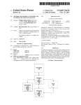
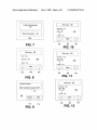
1
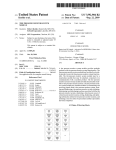
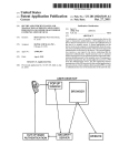
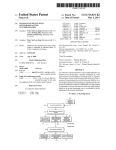
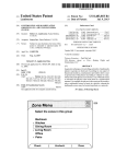
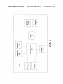
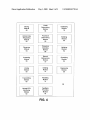
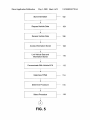
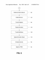
US 20080103718A1
(19) United States
(12) Patent Application Publication (10) Pub. N0.: US 2008/0103718 A1
Miller
(54)
(43) Pub. Date:
TIRE PRESSURE MONITOR INITIATION
TOOL WITH VEHICLE DATA INTERFACE
(76) Inventor:
(52)
Garret Miller, OWatonna, MN
(21)
US. Cl. .......................... .. 702/108; 340/442; 701/29
(57)
(Us)
May 1, 2008
ABSTRACT
A tire pressure monitor system tool stores information
Correspondence Address:
regarding a plurality of tire pressure monitor systems
BAKER & HOSTETLER LLP
WASHINGTON SQUARE, SUITE 1100s 1050
CONNECTICUT AVE‘ N‘W‘
installed on vehicles. The tool receives information regarding
a particular vehicle. Based on this information, the tool may
determine a particular tire pressure monitor system installed
WASHINGTON’ DC 20036-5304
on a vehicle. Based on the tire pressure monitor system
AP p1 NO _
11/589 091
installed on the vehicle, the tool may determine one or more
(22)
F?ed;
’
Oct_ 30, 2006
procedures that may be used With that tire pressure monitor
system. The tool may then instruct a user hoW to perform
certain procedures by presenting one or more displays to the
user on a display of the tool. The tool may also provide
(51)
Int_ CL
PubliC?tiOIl ClaSSi?CatiOIl
feedback to the user regarding a status of an initiation or other
G06F 19/00
B60C 23/02
G01M 1 7/00
(200601)
(200601)
(2006.01)
.
procedure, and reference a vehicle user manual. The tool may
interface With an electronic control unit of a vehicle. The tool
may also simulate a tire pressure sensor.
TPMS
.
.
Stormg
Determining
Displaying
Module
50
Module
64
Module
78
Vehicle Data
Procedure
Requesting
Determining
° ‘fl/"19
Module
52
Module
66
Module
8°
.
.
Receiving
Module
54
Access'ng
|
Procedure
_
I
selecting
Updating
Module
68
Module
82
Manual
S‘lmu l at'lng
56
R e ferenc'ng
Module
70
Module
N t_
Module
84
Linking
Initiating
Diagnosing
:Module
58
Module
72
Module
86
Transmitting
Resetting
‘ Module
Module
‘
50
74
H
Vehicle ECU
Feedback
Interfacing
Providing
Module
62
Module
76
Patent Application Publication
May 1, 2008 Sheet 1 0f 8
US 2008/0103718 A1
12
10\‘
2o
1
12
4
/28
18
/
@
_
QEY
\ ‘P’ K
16¢
‘
10
16b
‘1)
16a
~h22
26
24
FIG- 1
FIG. 2
Patent Application Publication
May 1, 2008 Sheet 2 0f 8
630m zaqsw
ow
>235
52.8m
EwcF
US 2008/0103718 A1
3
mm
6380592
om
2tMo8m: 2
on
mm
hmx aw
in
Patent Application Publication
.
May 1, 2008 Sheet 3 of 8
US 2008/0103718 A1
TPMS
.
.
Storing
Determining
Displaying
Module
50
Module
64
Module
78
Vehicle Data
Requesting
Procedure
Determining
Notifyin
M d I9
Module
Module
52
66
_
_
Receiving
Module
54
_
Procedure
0 ue
8°
_
Selecting
Updating
Module
68
Module
82
Manual
.
.
Accessing
Referencing
Simulating
Module
56
Module
70
Module
84
Linking
Initiating
Diagnosing
:Module
58
MOdule
72
Module
86
Transmitting
Resetting
‘ Module
Module
1
60
74
m
Vehicle ECU
Feedback
Interfacing
Providing
Module
62
Module
76
FIG. 4
Patent Application Publication
May 1, 2008 Sheet 4 0f 8
Store Information
US 2008/0103718 A1
—
102
Request Vehicle Data
—
104
Receive Vehicle Data
——
106
Access Information Stored
—
108
1
Link Vehicle Data and
Information Stored
11o
Communicate With Vehicle ECU
—
112
Determine TPMS
—
114
—
116
—
118
1
Determine Procedure
1
Select Procedure
FIG. 5
Patent Application Publication
May 1, 2008 Sheet 5 0f 8
US 2008/0103718 A1
Reference Owner's Manual
—
120
Initiate Sensor(s)
—
122
Provide Feedback
——
124
——
126
———
128
——
130
——
132
——
134
1
Display Information
1
Provide Noti?cation
1
Update Information Stored
V
Simulate Sensor(s)
1
Diagnose TPMS
FIG. 6
Patent Application Publication
May 1, 2008 Sheet 6 0f 8
Product Name/Logo
US 2008/0103718 A1
Title Area - 158
152
Main Menu - 178a
Acura — 178b
Audi —O17Bc
Other Information - 154
1E
O
O
Unlisted — 178n
10
——
A
162
FIG' 7
Enter
V
166
1Ei4
FIG. 10
Title Area - 158
Title Area - 158
Reset — 160a
_
Main Menu —182a
Diagnostics —160b
156
GT8 — 182b
-
DeVillg- 182c
Update - 16cc
1 0
0
O
Unlisted —162n
A
|
I
' Enter
A
Enter
||
I
I
166
l
162
l
166
v
‘
162
V
4
|:|G_ 8
V
|
r
|
164
FIG. 11
Current Vehicle
Title Area - 158
'
Main Menu — 186a
2005 Cadlllac Escalade EXT
170
2O06_1B6b
2005-1860
m
8
UnIistgd —186n
_
Reuse
172
|=|G_ 9
New
174
A
Enter
V
l
I
l
|
|
l
166
164
162
FIG. 12
Patent Application Publication
May 1, 2008 Sheet 7 0f 8
US 2008/0103718 A1
. Title Area - 158
Text Area - 190
Text Area - 190
Main Menu
M
|
Next
E
r
Next
r
|
I
l
192
194
194
FIG. 1 3
FIG. 15
Text Area - 190
L
F
Text Area - 190
Start
192
FIG. 14
198
FIG- 16
R
F
Patent Application Publication
May 1, 2008 Sheet 8 0f 8
US 2008/0103718 A1
5
Text Area - 190
218-) I
E
lMainiMenu
Yjes
I
g
192
208
210
A
I\
ID: 1234567
PSI: 32.3
A 216
Learn Mode
190
lMainK32iMenu‘ I AftivateJ
2210
FIG. 17
FIG. 19
xii
Text Area - 190
2184*
\
ID: 1234567
PSI: 32.3
6 Learn Mode
Main Menu
E
Main Menu
192:
FIG. 18
Activate
I
E
192
220
FIG. 20
190
May 1, 2008
US 2008/0103718 A1
TIRE PRESSURE MONITOR INITIATION
TOOL WITH VEHICLE DATA INTERFACE
existing tire. It should be readily apparent that neW/modi?ed
identi?cation and location information regarding the tire
must be provided or “taught” to the ECU.
RELATED APPLICATIONS
[0001] This application is related to co-pending US. patent
application titled “Tire Pressure Monitor System Tool With
Vehicle Entry System,” ?led concurrently herewith, co-pend
ing US. patent application titled “Tire Pressure Monitor Sys
tem Module,” ?led concurrently hereWith, and co-pending
US. patent application titled “Tire Pressure Monitor System
Tool With Re-Learn and Diagnostic Procedures,” ?led con
currently hereWith, each of Which is incorporated herein by
reference in its entirety.
FIELD OF THE INVENTION
[0002]
The invention relates generally to tire pressure
monitor systems. More particularly, the invention relates to a
handheld tire pressure monitor system tool that interfaces
With a vehicle electronic control unit.
BACKGROUND OF THE INVENTION
[0003]
Systems have been developed to monitor, for
example, vehicle tire pressure, and to report the tire pressure
[0006]
In order to accomplish the “teaching” of the tire
identi?cation information to a vehicle-based portion, one
knoWn tire identi?cation system is placed in a “leam” mode
via actuation of pushbutton(s) on an operator-accessible
information panel of the vehicle-based portion. During the
learn mode, the vehicle-based portion is in a ready state to
receive a distinctive “learn” mode signal transmitted from
each of tire-based transmitter of the system. In order to cause
each tire-based transmitter to send the “leam” mode signal, a
strong magnet is sWept over the outside of the associated
vehicle tire.
[0007] A monitor is located at each tire and periodically
takes a measurement of the tire pressure. A pressure signal is
generated that corresponds to the pres sure Within the tire. The
monitor transmits the measurement in a radio frequency
transmission to the central monitoring station that produces
an alarm or a display in response to the measurement. When
the tire pressure drops beloW a predetermined pressure, an
indicator is used to signal the vehicle operator of the loW
pressure.
to a receiver at a central monitoring station using radio trans
[0008]
missions. A typical remote automotive tire condition moni
toring system includes a plurality of tire-based sensory tran
sponders and a central, vehicle-based arrangement. The
sensory transponders include a component that senses a tire
tire rotation or tire replacement, the tire pressure system must
be calibrated. Calibration involves associating the various tire
positions With the pressure transmitters that are located on the
tires. One proposed method for calibrating a system uses a
magnet device to initiate the calibration. In this system, an
condition, such as tire in?ation pressure or tire temperature.
Each transponder is capable of outputting a coded transmis
sion that conveys sensed tire condition information and an
identi?er for reception by the vehicle-based arrangement.
Within the vehicle-based arrangement, an electronic control
unit (“ECU”) processes the conveyed information and con
trols provision of information regarding the sensed tire con
ditions to a vehicle operator. During operation of such a
system, the vehicle operator is readily noti?ed of a current tire
condition, such as a loW in?ation pressure in a tire.
[0004] For a vehicle operator to determine Which tire has a
condition of interest (e.g., a loW in?ation pressure), informa
tion provided to the vehicle operator must unambiguously
identify the location (e.g., right front) of the tire that has the
condition of interest. In order for the ECU to provide such tire
location information, the ECU has a memory that stores tire
identi?cation information for comparison With the identi?ca
tion conveyed from the transponder. Also, Within the memory,
a certain tire location is associated With each stored tire iden
ti?cation. Thus, once a provided identi?cation is matched to
a stored identi?cation, a location on the vehicle is associated
With the provided tire condition information. Accordingly,
the operator is made aWare that the tire at a certain location
(e. g., right front) has the certain condition (e.g., loW in?ation
pressure).
[0005]
Changes routinely occur regarding the tires and/or
transponders that are associated With a vehicle. The changes
can result in neW, different transponders being associated
With the vehicle, or a rearrangement of the locations of the
transponders, via rearrangement of the tires. Examples of
During assembly and routine maintenance such as
internal display panel With locations corresponding to the tire
location is activated. When the tire locations are illuminated
on the display, the vehicle operator or service technician
places the magnet near the indicated tire. The transducer then
sends a code corresponding thereto to the central controller.
When the indicator indicates another tire location, the magnet
must be brought near each tire location until each of the tire
locations have a tire registered thereto. One problem With this
device is that a separate component such as a magnet must be
provided to the vehicle operator that is used only in the
calibration process. One problem associated With a separate
magnet device is that such a device is subject to loss. Thus, the
tire pressure sensing system Would be rendered inoperable.
[0009] One problem With such systems is the need to pro
gram the location of the transmitters at the central station. To
be useful, the tire pressure is preferably associated With the
tire Which originated the measurement When presenting a
display or alarm. Each monitor includes identi?cation infor
mation that can be transmitted With the measurement. The tire
monitor is preferably activated to produce this information
and the information is conveyed to the central station and
associated With the position of the tire.
[0010] In one technique, the tire monitors include a reed
sWitch or other magnetic device. A magnet is passed near the
reed sWitch causing the monitor to transmit a radio frequency
transmission that includes identi?cation data. A service tech
nician repeats this process at each Wheel and then loads the
identi?cation and position information into the central moni
such changes occur When one or more neW tires With neW
toring station.
transponders are mounted on a vehicle (e.g., the placement of
the initial set of tires during vehicle manufacture or replace
many Wheels are made from steel Which is a magnetic mate
ment of one or more tires), When the tires are rotated during
routine maintenance, or When a transponder is replaced on an
because the steel Wheels may shield the magnetic energy.
[0011]
One drawback With such a system is that because
rial, tire pressure sensing systems may not operate properly
May 1, 2008
US 2008/0103718 A1
Therefore, the system may also be rendered inoperable
because the pressure transmitter is not activated by the mag
net.
[0012]
Various tire manufacturers have suggested various
locations for the pressure sensors. Known systems include
coupling a pressure sensor to the valve stem of the tire. Other
knoWn systems and proposed systems locate the pressure
sensors in various locations Within the tire Wall or tread.
[0013] These previous techniques have been limited in
effectiveness. The magnetic programming technique may be
subject to interference and crosstalk, for example in a factory
Where many such tire monitors are being assembled With tires
and vehicles. Also, users of modular products are required to
purchase a separate tool to interface With tire pressure moni
tor systems.
SUMMARY OF THE INVENTION
[0014] In accordance With one embodiment of the inven
tion, a tire pressure monitor system tool is provided that
combines various tire pressure sensor initiation functions
With a vehicle data stream interface. The tool may store infor
mation regarding a plurality of tire pres sure monitor systems
that may be installed on one or more vehicles. The informa
tion may identify, for example, initiation procedures that may
be used With a particular tire pressure monitor system and the
tire pressure monitor systems installed on particular vehicles.
The tool receives information regarding a particular vehicle.
appreciated. There are, of course, additional embodiments of
the invention that Will be described beloW and Which Will
form the subject matter of the claims appended hereto.
[0018] In this respect, before explaining at least one
embodiment of the invention in detail, it is to be understood
that the invention is not limited in its application to the details
of construction and to the arrangements of the components set
forth in the folloWing description or illustrated in the draW
ings. The invention is capable of embodiments in addition to
those described and of being practiced and carried out in
various Ways. For example, although the invention is
described in terms of a plurality of modules, it is to be under
stood that the invention may be implemented using one or
more modules. Also, it is to be understood that the phraseol
ogy and terminology employed herein, as Well as the abstract,
are for the purpose of description and should not be regarded
as limiting.
[0019] As such, those skilled in the art Will appreciate that
the conception upon Which this disclosure is based may
readily be utiliZed as a basis for the designing of other struc
tures, methods and systems for carrying out the several pur
poses of the present invention. It is important, therefore, that
the claims be regarded as including such equivalent construc
tions insofar as they do not depart from the spirit and scope of
the present invention.
BRIEF DESCRIPTION OF THE DRAWINGS
The information may be, for example, make, model, and year
[0020]
information. Based on this information, the tool may deter
mounting tool according to one embodiment of the invention.
mine a particular tire pressure monitor system installed on a
[0021] FIG. 2 is a rear vieW of a tire pressure monitor tool
according to one embodiment of the invention.
[0022] FIG. 3 is a block diagram of a tire pressure monitor
tool according to one embodiment of the invention.
[0023] FIG. 4 is a block diagram of a tire pressure monitor
tool according to one embodiment of the invention.
[0024] FIGS. 5 and 6 illustrate a method of communicating
With a tire pressure monitor system of a vehicle according to
one embodiment of the invention.
[0025] FIGS. 7-9 illustrate initial screens that may be dis
played by a tire pressure monitor tool according to one
embodiment of the invention.
[0026] FIGS. 10-18 illustrate procedure screens that may
be displayed by a tire pressure monitor tool according to one
embodiment of the invention.
vehicle that has data matching the information. Based on the
tire pressure monitor system installed on the vehicle, the tool
may determine one or more initiation procedures that may be
used With that tire pressure monitor system.
[0015]
The tool may have the one or more initiation proce
dures stored by a storing module provided in the tool. The tool
may then instruct a vehicle technician or other user hoW to
initiate the tire pressure monitor system of the vehicle by
presenting one or more displays to the user on a display of the
tool. The displays may provide step-by-step instructions
regarding hoW to initiate the tire pressure monitor system of
the vehicle. The tool may also provide feedback to the user
regarding a status of an initiation or other procedure, and
reference a vehicle user manual.
[0016] In accordance With another embodiment of the
invention, the tool may interface With an electronic control
unit of a vehicle. This may be useful, for example, for diag
nosing problems With a tire pressure monitor system. By
interfacing With the electronic control unit, the tool may
determine a tire pressure monitor system installed on the
vehicle, use functions of the electronic control unit to analyZe
a tire pressure monitor system, and provide notice to a user
regarding completion of a procedure. For example, by inter
FIG. 1 is a front perspective vieW of a tire pressure
[0027] FIGS. 19-20 illustrate diagnostic procedure screens
that may be displayed by a tire pressure monitor tool accord
ing to one embodiment of the invention.
DETAILED DESCRIPTION
[0028] FIG. 1 illustrates a tire pressure monitor tool 10
according to one embodiment of the invention. The tool 10
may cause a vehicle horn to sound or one or more lights to
includes an antenna 12, display 14, selector button 16a-16c,
port 18, a poWer button 20, a casing 22, and passages 24. The
antenna 12 may be used to transmit signals from the tool 10 to
?ash to indicate that a procedure has been successfully com
pleted. Additionally, the tool may simulate a tire pressure
an electronic control unit of a vehicle and a tire pressure
sensor mounted, for example, on a rim or tire of a vehicle. The
sensor and communicate With the electronic control unit of
the vehicle to determine Whether a tire pres sure sensor is fully
regarding, for example, the tool 10, a tire pressure monitor
facing With the electronic control unit of the vehicle, the tool
operational.
[0017]
There has thus been outlined, rather broadly, certain
display 14 may be used to display information to a user
system of a vehicle or status information regarding a resetting
or diagnostic function of the tool 10. The selector buttons
embodiments of the invention in order that the detailed
16a-16c may be used to navigate through the displays pre
description thereof herein may be better understood, and in
sented on the display 14 and select that certain functions be
order that the present contribution to the art may be better
performed. The selector buttons 16a-16c may be positioned
May 1, 2008
US 2008/0103718 A1
below select displays presented on the display 14. The selec
tor buttons 16a-16c may be used to select one of the selection
displays presented on display 14. The selection displays may
be, for example, up and doWn arrows, an enter function, a
menu function, start, activate, and next operations, yes, no,
okay, redo, and stop functions, and reuse or neW functions.
The selection displays are described in further detail beloW.
[0029] The port 18 may be a port that enables the tool 10 to
be connected to, for example, a computer or lntemet connec
tion that enables the tool to be updated With modi?ed or
additional information. The port 18 may be, for example, an
RS232 serial port that connects the tool 10 to the computer or
Internet connection using an RS232 serial cable. This is
described in further detail beloW.
[0030] The poWer button 20 may be used to turn the tool 10
on and off. According to one embodiment of the invention, the
tool may turn off automatically after, for example, three to
four minutes of inactivity.
[0031] The casing 22 provides a housing for the tool 10.
The casing may be provided With the passages 24 that may be
located in front of a speaker (not shoWn) that emits audible
tones or other noti?cations While the tool 10 is being used.
[0032] FIG. 2 illustrates a rear vieW of the tool 10 according
one embodiment of the invention. The tool 10 may be battery
poWered. Therefore, the tool 10 may be provided With a
battery compartment 26. The battery compartment 26 may
include a removable battery cover 28 that alloWs removable
insertion of batteries Within the battery compartment 26.
According to one embodiment of the invention, the tool 10 is
poWered by three (3) siZe C batteries.
[0033]
FIG. 3 illustrates a block diagram of the tool 10
illustrated in FIGS. 1 and 2. The tool 10 may include a
microprocessor 30 that processes softWare used to operate the
tool 10. According to one embodiment of the invention, the
microprocessor is an ATMEGA2561 microprocessor having
a clock speed of 8 MhZ. The microprocessor 30 communi
cates With a keypad 32. According to one embodiment of the
invention, the keypad 32 includes the selector buttons 1611
16c illustrated in FIG. 1. The microprocessor 30 may also be
in communication With a speaker 34. The speaker 34 may be
cation With a poWer regulator 42. The poWer regulator 42 may
be used to regulate the poWer supplied to each device of the
tool 10.
[0037] FIG. 4 illustrates a block diagram of the tire pres sure
monitor tool 10 shoWn in FIGS. 1 and 2 according to one
embodiment of the invention. The tool 10 may include a
storing module 50 that stores information regarding a plural
ity of tire pressure monitor systems. According to one
embodiment of the invention, the information stored relates to
a plurality of tire pressure monitor systems from a variety of
vehicle manufactures and various models and years of the
vehicles. The storing module 50 may be, for example, any
suitable storage medium such as a storage module on a micro
processor, a hard disk, a removable storage media such as a
?ash disk for other suitable storage mechanism. The tool 10
also includes a vehicle data requesting module 52. The
vehicle data requesting module 52 may be used to request
data regarding a particular vehicle for Which the tool 10 may
be used. The vehicle data requesting module 52 may present
a user of the tool 10 With a plurality of screens displaying
information regarding various vehicle types. For example, the
user may be presented With the vehicle data associated With
the vehicle for Which the tool 10 Was most recently used.
According to another embodiment, the user may be presented
With a series of screens displaying lists of various makes,
models, and years of various vehicles. The user may use the
selector buttons to navigate the lists and select the make,
model, and year of a desired vehicle. A receiving module 54
may be used to receive input provided by the user.
[0038] An accessing module 56 may be used to access the
information stored in the storing module 50 to determine
Whether any of the information stored by the storing module
50 is associated With the vehicle data input by the user. If the
storing module 50 does not include any information associ
ated With the vehicle data, the user may be noti?ed that no
information Was located. If information associated With the
vehicle data is located, hoWever, a linking module 58 may be
used to link the information With the vehicle data. The infor
mation may include, for example, communication protocols
used to provide audible tones or noti?cations during use of the
tool 10.
for communicating With an electronic control unit of the
vehicle, procedures for resetting a tire pressure monitor sys
tem of the vehicle, diagnosing the tire pressure monitor sys
[0034]
tem of the vehicle or other functions.
The microprocessor 30 may also be in communica
tion With a transmitter 3 6 and a receiver 38. The transmitter 3 6
may be used to transmit signals to a tire pressure sensor
mounted on a Wheel of a vehicle or an electronic control unit
of a vehicle. According to one embodiment of the invention,
the transmitter 36 operates at 125 khZ. Although only one
transmitter is shoWn, it is to be understood that multiple
transmitters including transmitters of different types may be
used.
[0035] The receiver 38 maybe used to receive signals trans
mitted from a tire pres sure sensor mounted on a Wheel vehicle
and an electronic control unit of a vehicle. According to one
[0039]
A transmitting module 60 may then be used to trans
mit a signal from the tool 10 to a tire pressure sensor of the
vehicle or an electronic control unit of the vehicle. If the
signal is transmitted to the electronic control unit of the
vehicle, a vehicle electronic control unit interfacing module
62 may be used to interface With the vehicle electronic control
unit. The tool 10 may interface With the vehicle electronic
control unit to, for example, reset a tire pressure monitor
system of the vehicle. As discussed above, tire replacement
and rotation requires resetting of the vehicle’s tire pressure
monitor system. This enables the vehicle electronic control
embodiment of the invention the receiver 38 may operate at
315 MhZ and have a clock speed of 10.178 MhZ. Altema
tively, the receiver 38 may operate at 433 M112 and have a
unit to maintain locations of each tire pressure sensor such
that accurate information may be displayed to a driver of the
clock speed of 13.225 MhZ. Although only one receiver is
shoWn, it is to be understood that multiple receivers operating
at different frequencies and having different clock speeds
vehicle.
may be used.
[0036] The tool 10 may also include a poWer supply 40. As
stated above, the poWer supply may be, for example, three (3)
siZe C batteries. The poWer supply 40 may be in communi
vehicle using, for example, a dashboard display of the
[0040]
A tire pressure monitor system determining module
64 may be used to determine a type of tire pressure monitor
system provided on the vehicle. This information may be
obtained, for example, from the vehicle electronic control
unit or by matching the vehicle data With vehicle data pro
vided in a lookup table stored by the tool. The vehicle data
May 1, 2008
US 2008/0103718 A1
may be associated With the particular type of tire pressure
monitor system installed on the vehicle. Upon determining
the tire pressure monitor system installed on the vehicle, a
procedure determining module 66 may determine a proce
dure to be folloWed to, for example, reset or diagnose the tire
pressure monitor system of the vehicle. Based on instructions
input by a user, a procedure selecting module 68 selects the
procedure corresponding to the instructions input by the user.
Some procedures may require a user to perform procedures
speci?c to a vehicle. These procedures are typically located in
an oWner’ s manual of the vehicle. Therefore, a manual refer
encing module 70 may be used to refer to the oWner’ s manual
so that the user may perform this procedure prior to continu
ing to use the tool 10.
[0041] According to one embodiment of the invention, an
initiating module 72 may be used to initiate one or more tire
pressure sensors of a vehicle. Initiating the tire pressure sen
sors places the sensors in a state that enables the sensors to
communicate With the tool 10 and the electronic control unit
of the vehicle. After initiating the sensors, the tire pressure
monitor system of the vehicle may be, for example, reset
using resetting module 74. The resetting module 74 enables
the electronic control unit of the vehicle to determine loca
tions, identi?cation numbers, and other information regard
ing the tire pressure sensors mounted one or more Wheels of
the vehicle. According to one embodiment of the invention,
the antenna 12 of the tool 10 is placed adjacent a valve stem
of a Wheel of a vehicle. The tool 10 receives, for example,
location, identi?cation number, pressure information, and
possibly other information from the tire pres sure sensor using
receiving module 54 and transmits the information to the
vehicle electronic control unit using transmitting module 60.
[0042] A feedback providing module 76 may be used to
determine Whether the tire pressure monitor system has been
reset. For example, the feedback providing module 76 may
cause symbols, text or other information to be displayed on
the display 14 indicating that a reset procedure has been
completed. The information may be displayed on the display
14 using displaying module 78. A notifying module 80 may
be used to notify the user that a reset or other procedure has
been completed. For example, the notifying module 80 may
cause an electronic control unit of a vehicle to sound a horn of
the vehicle or ?ash one or more lights of a vehicle indicating
[0046]
FIGS. 5-6 illustrate a method of communicating
With a tire pressure monitor system of a vehicle using a tire
pressure monitor tool according to one embodiment of the
invention. In step 102, information regarding tire pressure
monitor systems and vehicles using such vehicles may be
stored by the tire pressure monitor tool. The tool may be used
to obtain tire pressure information from one or more Wheels
of a vehicle provided With tire pressure sensors. To commu
nicate properly With a tire pressure sensor, the tire pressure
tool must be provided With data regarding the vehicle from
Which tire pressure information is sought. Vehicle data may
be requested using the tool as illustrated in step 104. Vehicle
data may be requested by, for example, displaying a make,
model, and year of a vehicle and requesting that the user
con?rm or change the vehicle data.
[0047] If the vehicle data displayed is not related to the
vehicle from Which tire pressure information is sought, the
tool may provide a series of displays to the user enabling the
user to select a make, model, and year data from among a list
of makes, models, and years. This information may be
received by the tool in step 106. The information stored in step
102 is then accessed in step 108 to determine Whether tire
pressure monitor system information relating to the vehicle
data received by the tool is being stored. If information relat
ing to the vehicle data is located, this information is linked
With the vehicle data in step 110.
[0048]
The tool may use this information to communicate
With the electronic control unit of the vehicle, step 112. Based
on the communication With the electronic control unit, a
determination may be made regarding a tire pressure monitor
system installed on the vehicle 114. Based on the tire pressure
monitor system installed, a determination may be made
regarding a procedure to, for example, reset or diagnose the
tire pressure monitor system, step 116. The resetting or diag
nosing procedure is then selected based on input provided by
a userusing the tool 10 as illustrated in step 118. The resetting
or diagnosing procedure may require a user to perform a
procedure particular to the vehicle. Therefore, the tool may
reference a vehicle oWner’s manual so that the user may
folloW the procedure identi?ed in the oWner’s manual, step
120. The procedure may be, for example, placing the vehicle
in a leam mode such that the vehicle or electronic control unit
is able to receive tire pressure monitor system information
from tire pressure sensors provided on one or more Wheels of
that the reset or other procedure has been completed.
[0043] An updating module 82 may be used to update the
the vehicle.
information stored by the storing module 50. The updating
provided on the Wheels of the vehicle may be initiated. Initi
[0049]
In step 122, one or more of the tire pressure sensors
module 82 may be in communication With the port 18. The
ating the tire pressure sensors enable the sensors to commu
updating module 82 may receive information from a com
puter, the Internet or other data source using, for example, an
nicate With the tool 10 and the vehicle electronic control unit.
RS232 serial cable connected to the port 18 and the computer
or other device. The updating module 82 may modify infor
mation stored by the storing module 50 or add information to
the storing module 50. Additional information may be, for
example, information relating to tire pressure monitor sys
placing an antenna of a tire pressure monitor tool adjacent or
near a valve stem of a Wheel of the vehicle. The tool 10
tems installed on neWer vehicles.
[0044] The tool 10 may also include a simulating module
84. The simulating module 84 may be used to simulate a tire
pressure sensor to validate the functionality of a tire pressure
monitor system on a vehicle.
[0045]
A diagnosing module 86 may also be used to diag
nose a tire pressure monitor system on a vehicle. The diag
Initiating the sensors may be performed by, for example,
transmits and receives information betWeen the vehicle elec
tronic control unit and the tire pressure sensor such that the
vehicle or the electronic control unit may determine a loca
tion, identi?cation number, tire pressure, or other information
from the tire pressure sensor.
[0050] Feedback may be provided to the user to, for
example, indicate that a sensor has been successfully initiated
or that the signal has been received by the tire pressure moni
tor tool, step 124. This information may be displayed on a
display of the tire pressure monitor tool as illustrated in step
nosing module 86 may be used to obtain, for example, tire
126. The user may also be noti?ed Whether a resetting or
pressure and other information from the sensor.
diagnosing procedure has been completed, step 128. For
May 1, 2008
US 2008/0103718 A1
example, the tool 10 may cause the electronic control unit of
displays 162, 164, and 166 to navigate and select a particular
the vehicle to sound a horn of the vehicle or ?ash one or more
vehicle make or a main menu option for returning to the main
lights of the vehicle indicating that the resetting or diagnosing
menu.
procedure has been completed.
[0055]
[0051] According to one embodiment of the invention, the
tool 10 maybe updated With modi?ed or additional tire pres
sure monitor system information, step 130. For example, the
tool may be provided With a port that receives, for example, an
presented With a display 180 as shoWn in FIG. 11. The display
RS232 serial cable that may be connected to a computer, the
Internet or other data source such that tire pressure monitor
system information may be communicated to the tool in step
130 and stored in step 102. The tire pressure monitor system
If a user selects a vehicle make, the user may then be
180 may enable a user to select a particular model associated
With the vehicle make selected using the display 176. The
display 180 may include a list of selectable models associated
With the vehicle make selected and also enable the user to
return to the main menu. The display 180 may also include the
selection displays 162, 164, and 166 as described. The user
may navigate the list provided in the display 180 and select a
information may include modi?cations or additions to the
desired model. If a user selects a desired model, the user may
information already stored by the tire pressure monitor tool.
be presented With a display 184 as illustrated in FIG. 12. The
display 184 may include a title area 158 and selection displays
162, 164, and 166 as described above. The display 184 may
[0052] The tool 10 may also simulate a tire pressure sensor
of a vehicle, step 132. The tool 10 may simulate the tire
pressure sensor to validate the functionality of a tire pressure
monitor system installed on a vehicle. The tool 10 may also be
used to diagnose the tire pressure monitor system, step 134.
The tool 10 may be used to obtain information such as tire
pressure and sensor identi?cation information. Additionally,
the tool 10 may obtain information regarding a battery con
dition of the batteries provided in the tire pressure monitor
tool 10.
[0053]
FIGS. 7-9 illustrate initial displays that may be pre
sented to a user of a tire pressure monitor tool according to
one embodiment of the invention. FIG. 7 illustrates a display
150 that may be, for example, a start up screen displayed on
the tire pressure monitor tool display. The display 150 may
include a product name and/or logo 152 and/or other infor
mation 154. FIG. 8 illustrates a display 156 that may be, for
example, a main menu of the tool. The display 156 may
include a title area 158 for displaying a title of the display. The
display 156 may include a plurality of a selectable options
160a-160c that may be displayed in a list in the display 156.
The selectable options 160a-160c may include, for example,
reset 160a, diagnostics 160b, and update 1600. The selectable
options 160a-160c may be navigated using selection displays
presented above selector buttons provided on the ?re pres sure
monitor tool. The selection displays may be, for example, an
up arroW 162 and a doWn arroW 164. By pressing the selector
buttons provided on the tool, a user may navigate up and doWn
the display 156 to select a desired function. The function may
be selected by pressing the selector button located beneath
selection display Enter 166 provided on the display 156. The
also include a list of years from Which a user can select a
desired year associated With the vehicle make and model
previously selected. The display 184 may include a list having
a main menu option 186a and a plurality of selectable years
186b-186n from Which the user may select.
[0056] If the user selects a vehicle year, the user may be
presented With a display 188 as illustrated in FIG. 13. The
display 188 may include a title area 158 that provides a title of
the display. The display 188 may also include a user instruc
tion 190 providing a user With an instruction to perform a task.
For example, the user may be instructed to refer to a particular
section of the vehicle’s user manual for performing a certain
function. The display 188 may also include main menu selec
tion display 192 and next selection display 194 displayed
above tWo of the selector buttons provided on the tire pres sure
monitor tool. The user may use the selection displays 192,
194 to return to a main menu of the tire pressure monitor tool
or proceed to a next step of, for example, a reset procedure
after performing the task instructed in the display 188.
[0057] If the user selects the next selection display 194, the
user may be presented With a display 196 as illustrated in FIG.
14. The display 196 includes an instruction 190 and a main
menu selection display 192 as discussed above. The display
196 may also include a start selection display 198 presented
above a selector button provided on the tire pressure monitor
tool. If the user selects the start selection display 198, the user
may be presented With a display 200 as illustrated in FIG. 15.
The display 200 may include a user instruction 190 and a next
selection display 194 as discussed above. After selecting the
highlighting, circling, underlining or other formatting to dis
next selection display 194 the user may be presented With a
display 202 as illustrated in FIG. 16.
tinguish the function to be selected among other selectable
functions.
204 illustrating that the tool is performing a function and may
tool may indicate a function to be selected by, for example,
[0054]
FIG. 9 illustrates a vehicle information screen dis
play 168 that displays information regarding a particular
vehicle. The display 168 may include an information display
area 170 that displays vehicle data regarding a particular
vehicle. The display 168 also includes selection displays 172,
174 that enable a user to either reuse the vehicle data provided
on the display 168 or create neW vehicle data, respectfully.
FIG. 10 illustrates a display 176 that enables a user to select a
vehicle make. The display 176 may include a title area 158
[0058]
The display 202 may provide text and/or graphics
provide details regarding that function. For example, during a
reset procedure, the display 202 may indicate that a left front
tire pressure sensor is being reset and instructs the user to
please Wait. The display 202 may also include a main menu
selection display 192 as discussed above.
[0059]
Upon completion of the function, a display 206 as
illustrated in FIG. 17 may be presented on the tire pressure
monitor tool. The display 206 may include a text area 190 that
provides information to the user and may also include an
that provides a title of the display. The display 176 may also
interrogatory. The interrogatory may be, for example, “Did
include a list of selectable options 178a-178n that a user may
born sound?”. The display 206 may include selection displays
use to either select a vehicle make or return to the main menu.
Yes 208 and No 210 that enable the user to ansWer the inter
The display 176 may also include the selection displays 162,
rogatory. The selection displays 208, 210 may be selected
using selector buttons provided on the tool and beloW the
164, and 166 described above. The user may use the selection
May 1, 2008
US 2008/0103718 A1
selection displays. The selection 206 may also include a main
menu selection display 192 as discussed above.
[0060] If the user selects Yes selection display 208, the user
may be presented With a display 212 as illustrated in FIG. 18.
The display 212 may include a text area 188 indicating that
4. The tool of claim 1, further comprising a storing module
con?gured to store information regarding at least one of a
maintenance history and at least one tire pressure monitor
system.
5. The tool of claim 4, further comprising an accessing
the procedure has been completed. The display 212 may also
module, in communication With the storing module, con?g
include a main menu selection display 192 as discussed
ured to access the information stored.
above. If the user selects No selection display 210, hoWever,
the tool may present a previous display such as, for example,
module, in communication With the storing module, con?g
display 196 as illustrated in FIG. 14. This enables the user to
repeat the procedure to attempt to properly complete the
procedure.
[0061] FIG. 19 illustrates a diagnostic test screen display
214 according to one embodiment of the invention. The dis
play 214 includes a text area 190 and main menu selection
display 192 as described above. The text display 190 may
include, for example, an identi?cation number of a tire pres
sure sensor from Which tire pressure information has been
received, the tire pres sure for that particular tire, and an oper
ating mode of the electronic control unit of the vehicle. The
display may also include a signal indicator 216 indicating
Whether a signal is being received from the tire sensor and a
battery level indicator 218 indicating an approximate battery
level remaining in the batteries of the tire pressure monitor
tool. The display 216 may also include an activate selection
display 220 that activates a diagnostic procedure of the tire
pressure monitor tool. Upon selection of the activate selection
display 220, a signal transmitting signal symbol 222 may be
presented in a display 218 to indicate that the tire pressure
monitor tool is transmitting a signal to the tire pressure sensor
as illustrated in FIG. 20.
[0062] The many features and advantages of the invention
are apparent from the detailed speci?cation, and thus, it is
intended by the appended claims to cover all such features
and advantages of the invention Which fall Within the true
spirit and scope of the invention. Further, since numerous
modi?cations and variations Will readily occur to those
skilled in the art, it is not desired to limit the invention to the
exact construction and operation illustrated and described,
and accordingly, all suitable modi?cations and equivalents
may be resorted to, falling Within the scope of the invention.
What is claimed is:
1. A tool for use With a tire pressure monitor system com
prising:
a vehicle control unit interfacing module;
a tire pressure monitor system determining module, in
communication With the vehicle control unit interfacing
module, con?gured to determine a tire pres sure monitor
system installed on a vehicle; and
a tire pressure sensor initiating module, in communication
With the tire pres sure monitor system determining mod
ule, con?gured to initiate at least one tire pressure sen
sor.
6. The tool of claim 4, further comprising an updating
ured to update the information stored by the storing module.
7. The tool of claim 1, further comprising a displaying
module con?gured to display at least one of vehicle informa
tion and tire pressure monitor system information.
8. The tool of claim 7, Wherein the tire pressure monitor
system information comprises at least one of ?re pres sure, tire
pressure sensor identi?cation, and sensor mode.
9. The tool of claim 1, further comprising a resetting mod
ule con?gured to reset the ?re pressure monitor system.
10. The tool of claim 9, further comprising a notifying
module, in communication With the resetting module, con
?gured to notify a user that a tire pressure monitor system has
been reset.
11. The tool of claim 10, Wherein the notifying module is
con?gured to notify the user by causing at least one of a
vehicle horn to sound and at least one vehicle light to ?ash.
12. The tool of claim 9, further comprising a manual ref
erencing module con?gured to reference a vehicle user
manual.
13. The tool of claim 12, further comprising an update
interface.
14. The tool of claim 13, Wherein the update interface
comprises an RS232 port.
15. The tool of claim 1, further comprising a diagnosing
module con?gured to diagnose the at least one tire pressure
sensor.
16. The tool of claim 1, Wherein the ?re pressure monitor
determining module requests vehicle data.
17. The tool of claim 16, Wherein the vehicle data com
prises vehicle make, model, and year data.
18. The tool of claim 1, Wherein the tire pressure sensor
initiating module comprises a feedback module con?gured to
provide feedback regarding at least one of a signal received by
the tool and successful initiation.
19. The tool of claim 1, further comprising a transmitting
module con?gured to transmit a signal from the tool to the tire
pressure monitor system.
20. The tool of claim 1, further comprising a receiving
module con?gured to receive a signal from at least one of the
tire pressure monitor system and the at least one tire pressure
sensor.
21. A tool for use With a tire pressure monitor system
comprising:
2. The tool of claim 1, further comprising a procedure
determining module, in communication With the tire pressure
interfacing means for interfacing With a vehicle electronic
monitor system determining module, con?gured to determine
tire pres sure monitor system determining means for deter
mining a tire pressure monitor system installed on a
an initiation procedure associated With the tire pressure moni
tor system.
3. The tool of claim 1, further comprising a procedure
selecting module, in communication With the tire pressure
monitor system determining module, con?gured to select an
initiation procedure associated With the tire pressure monitor
system.
control unit;
vehicle; and
tire pressure sensor initiating means for initiating at least
one tire pressure sensor.
22. The tool of claim 21, further comprising initiation
procedure determining means for determining an initiation
procedure associated With the tire pressure monitor system.
May 1, 2008
US 2008/0103718 A1
23. The tool of claim 21, further comprising initiation
procedure selecting means for selecting an initiation proce
dure associated With the tire pressure monitor system.
24. The tool of claim 21, further comprising storing means
for storing information regarding at least one of a mainte
nance history and at least one tire pressure monitor system.
25. The tool of claim 24, further comprising accessing
means for accessing the information stored.
26. The tool of claim 24, further comprising updating
means for updating the information stored.
27. The tool of claim 21, further comprising displaying
means for displaying at least one of vehicle information and
tire pressure monitor system information.
28. The tool of claim 27, Wherein the tire pressure monitor
system information comprises at least one of tire pressure, tire
pressure sensor identi?cation, and sensor mode.
29. The tool of claim 21, further comprising resetting
means for resetting the tire pressure monitor system.
30. The tool of claim 29, further comprising notifying
means for notifying a user that a tire pressure monitor system
has been reset.
31. The tool of claim 30, Wherein the notifying means is
con?gured to notify the user by causing at least one of a
interfacing a tire pressure monitor tool With a vehicle elec
tronic control unit;
determining a tire pressure monitor system installed on a
vehicle; and
initiating at least one tire pressure sensor.
42. The method of claim 41, further comprising determin
ing an initiation procedure associated With the tire pressure
monitor system.
43. The method of claim 41, further comprising selecting
an initiation procedure associated With the tire pressure moni
tor system.
44. The method of claim 41, farther comprising storing
information regarding at least one of a maintenance history
and at least one tire pressure monitor system.
45. The method of claim 44, further comprising accessing
the information stored.
46. The method of claim 44, further comprising updating
the information stored.
47. The method of claim 41, further comprising displaying
at least one of vehicle information and tire pressure monitor
system information.
48. The method of claim 47, Wherein the tire pressure
monitor system information comprises at least one of tire
pressure, tire pressure sensor identi?cation, and sensor mode.
vehicle horn to sound and at least one vehicle light to ?ash.
49. The method of claim 41, further comprising resetting
32. The tool of claim 29, further comprising manual refer
the tire pressure monitor system.
50. The method of claim 49, further comprising notifying a
encing means for referencing a vehicle user manual.
33. The tool of claim 32, further comprising update inter
facing means for interfacing With the storing module.
34. The tool of claim 33, Wherein the update interfacing
user that a tire pressure monitor system has been reset.
means comprises an RS232 port.
light to ?ash.
52. The method of claim 49, further comprising referenc
35. The tool of claim 21, further comprising diagnosing
51. The method of claim 50, Wherein the notifying causes
at least one of a vehicle horn to sound and at least one vehicle
means for diagnosing the at least one tire pressure sensor.
ing a vehicle user manual.
36. The tool of claim 21, Wherein the tire pressure monitor
system determining means requests vehicle data.
37. The tool of claim 36, Wherein the vehicle data com
an RS232 port.
prises vehicle make, model, and year data.
the at least one tire pressure sensor.
38. The tool of claim 21, Wherein the tire pressure sensor
initiating means comprises feedback means for providing
feedback regarding at least one of a signal received by the tool
and successful initiation.
39. The tool of claim 21, further comprising transmitting
means for transmitting a signal from the tool to the tire pres
sure monitor system.
40. The tool of claim 21, further comprising receiving
means for receiving a signal from at least one of the tire
pressure monitor system and the at least one tire pressure
sensor.
41. A method of using a tire pressure monitor system
comprising:
53. The method of claim 41, Wherein the interfacing uses
54. The method of claim 41, further comprising diagnosing
55. The method of claim 41, Wherein the tire pressure
monitor determining comprises requesting vehicle data.
56. The method of claim 55, Wherein the vehicle data
comprises vehicle make, model, and year data.
57. The method of claim 41, Wherein the initiating com
prises providing feedback regarding at least one of a signal
received by the tool and successful initiation.
58. The method of claim 41, further comprising transmit
ting a signal from the tool to the tire pressure monitor system.
59. The method of claim 41, further comprising receiving
a signal from at least one of the tire pressure monitor system
and the at least one tire pressure sensor.
*
*
*
*
*


![`95385109 1%]?](http://vs1.manualzilla.com/store/data/005699459_1-7fc02fda0f8970d7c2f678aea00486d8-150x150.png)