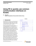
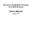
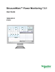
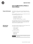
1
 MDC‐700 Series User Manual
November 2014, Version 1.00 The MDC‐700 series module is a Modbus Data Concentrator that has the ability to communicate with up to 127 Modbus slave devices using Modbus RTU protocol. The MDC‐700 series module also supports the Modbus TCP protocol for communication with PC‐based applications such as SCADA (Supervisor Control and Data Acquisition) and HMI (Human Machine Interface) programs. The following sections will help you to set up your MDC‐711/MDC‐714 and show you how to use the web interface to obtain configuration and other information relative to the MDC‐711/MDC‐714 module and associated slave devices. Basic operating procedure STEP 1 Assign an IP address to the MDC‐711/MDC‐714. STEP 2 Edit the config.csv file. Note that before editing this file, you should confirm the parameter value for any associated Slave devices. STEP 3 Upload the config.csv file to the MDC‐711/MDC‐714. STEP 4 Verify the status of both the connection and the configuration by browsing the web. Copyright © 2014 ICP DAS Co., Ltd. All Rights Reserved. ∗ E‐mail: [email protected] ‐ 1 ‐ Assigning an IP address to MDC‐700 The MDC‐711/MDC‐714 is an Ethernet device, which comes with a default IP address; therefore, you must first assign a new IP address to the module. To access the MDC‐711/MDC‐711 by using web‐based interface, you must know the IP address the MDC‐711/MDC‐714 is using. The MDC‐711/MDC‐714 uses the factory default IP address of 192.168.255.1 by default. STEP 1 Power on the computer and the MDC‐711/MDC‐714. STEP 2 Set the IP configuration on your computer. If the MDC‐711/MDC‐714 is using the default IP address of 192.168.255.1, you must chose an IP address for the computer in the range of 192.168.255.2 – 192.168.255.253 that is not already in use. NOTE: Details on how to change the IP address on your computer depend upon the type architecture and operating system you are using. Use the computer Help and Support functionality to search for “IP Addressing”. STEP 3 Open a web browser and go to the website at http://192.168.255.1, where 192.168.255.1 is the default IP address of your MDC‐711/MDC‐714. STEP 4 Open the IP address configuration interface by clicking the Ethernet Configuration. STEP 5 Choose a new IP address for your MDC‐711/MDC‐714. Make sure that the address you pick is not currently in use by another device on the network. Copyright © 2014 ICP DAS Co., Ltd. All Rights Reserved. ∗ E‐mail: [email protected] ‐ 2 ‐ NOTE: The MDC‐711/MDC‐714 can be reset to factory defaults by shorting the RESET pin to GND pin for 3 seconds. The LED display will show “RESET” as below and remove the IP address set previously for the MDC‐711/MDC‐714. Copyright © 2014 ICP DAS Co., Ltd. All Rights Reserved. ∗ E‐mail: [email protected] ‐ 3 ‐ Editing the config.csv file The MDC‐711/MDC‐714 module is configured using the config.csv file, which can be edited to work with your RTU slave devices. The Comma Separated Values (CSV) files can be viewed and edited in spreadsheet applications like Microsoft Excel, or in any text editor. The following describes how to edit the configuration file for your devices. The figures below illustrate the four main sections that need to be edited: Modbus Connection, Module information, COM Port Configuration and Polling Definition. Modbus Connection The Modbus Connection section is used to configure the parameters for the Modbus ID of MDC‐711/MDC‐714 and TCP/IP Port number. # * TCPPort ModbusID 502 1
TCPPort: Define the TCP/IP Port number. ModbusID: Define the Modbus ID of MDC‐711/MDC‐714. Module Information The Module Information section is used to record relative information for the MDC‐711/MDC‐714. # * ModbusInfo this is my data concentrator
ModuleInfo: Define the relative information for MDC‐711/MDC‐714. The string constant has a maximum length of 32 characters. Copyright © 2014 ICP DAS Co., Ltd. All Rights Reserved. ∗ E‐mail: [email protected] ‐ 4 ‐ COM Port Configuration The Connection Configuration for RS‐485 section is used to configure the parameters for the connection between the MDC‐711/MDC‐714 module and the RTU slave devices. # ComPortNo BaudRate DataBit Parity
StopBit
Timeout PollDelay OperatingMode
* 1 115200 8 0
1
100
20 Master
* 2 115200 8 0
1
100
20 Master
* 3 115200 8 0
1
100
20 Master
* 4 115200 8 0
1
100
20 Master
* 5 115200 8 0
1
100
20 Master
Each Connection Configuration consists of 8 parameters. The definitions of the parameters are as follows. ComPortNo: Indicates the COM number used in MDC‐711/MDC‐714. The COM port number can be 1 or 2 for MDC‐711. The COM port number can be 1, 2, 3, 4 or 5 for MDC‐714. BaudRate: Defines the transmission speed between the MDC‐711/MDC‐714 and the RTU slave devices. The baud rate can be set to 4800 bps, 9600 bps, 19200 bps, 34800 bps, 57600 bps or 115200 bps depending on the RTU slave device being used. DataBit: Defines the number of data bits in each character. Either7 or 8 can be selected. Be sure this setting is the same as the setting for the RTU slave device. Parity: Defines the Parity bit. The parity bit can be set to 0 (none), 1 (even) or 2 (odd). StopBit: Defines the Stop bits. Either 1 or 2 can be selected. Timeout: Defines the period of time that the MDC‐711/MDC‐714 will wait for a response from the RTU slave device. PollDelay: Defines the Poll Delay between each scan for Modbus RTU communication. The units are milliseconds (ms). OperatingMode: This parameter can be ignored for now.
Copyright © 2014 ICP DAS Co., Ltd. All Rights Reserved. ∗ E‐mail: [email protected] ‐ 5 ‐ Polling Definition Before attempting to configure the parameters for the Polling Definition, be sure to check the settings for Com port, the slave address, the function code and the quantity of registers. # UseComPort SlaveModbusID FunctionCode RegStartAddr RegCount
* 1 1 1
0
8
* 1 1 2
0
8
* 2 2 1
0
4
* 3 3 2
0
4
* 4 4 3
0
4
* 5 5 4
0
4
Each Polling Definition consists of 5 parameters. The definitions of the parameters are as follows. UseComPort: Defines the COM port to be used to connect between the slave device and the MDC‐711/MDC‐714 module. The COM port number can be 1 or 2 for MDC‐711. The COM port number can be 1, 2, 3, 4 or 5 for MDC‐714. SlaveModbusID: Defines the identification of the remote slave. The valid range is from 1 to 255. FunctionCode: Defines the request function code. A valid code can be 1 (Read DO), 2 (Read DI), 3 (Read AO) or 4 (Read AI) depending on the I/O features of the slave device. RegStartAddr: Defines the starting address, i.e. the address of the first register specified. The valid range is from 0 to 8192. RegCount: Define the quantity of registers to be read. The valid value is from 1 to 64. NOTE: y The total number of the polling definitions must not exceed 127. y The MDC‐711/MDC‐714 provides a total of 4127 internal Modbus registers, 4000 of them are used to hold data collected from the RTU slave devices, meaning that the total number of registers that can be read from slave devices must not exceed 4000. y The Modbus address for the MDC‐711/MDC‐714 module is allocated automatically. Copyright © 2014 ICP DAS Co., Ltd. All Rights Reserved. ∗ E‐mail: [email protected] ‐ 6 ‐ Importing/exporting configuration files in CSV format Go to the web interface at http://xxx.xxx.xxx.xxx, where xxx.xxx.xxx.xxx is the IP address of your MDC‐711/MDC‐714. Any standard browser can be used to interface the MDC‐711/MDC‐714, such as Mozilla Firefox, Internet Explorer or Google Chrome. NOTE: If you haven’t changed the default of the MDC‐711/MDC‐714, please refer to “Assigning an IP address to MDC‐700” to configure it. Importing a CSV file to MDC‐711/MDC‐714 STEP 1 Open the Import and Export interface by clicking the Import/Export Configuration button. STEP 2 Choose a CSV file from your computer by clicking the Choose File button. STEP 3 Click the Import button to import the config.csv file to the MDC‐711/MDC‐714. NOTE: After the import process is finished, the MDC‐711/MDC‐714 will reboot in 5 seconds. Copyright © 2014 ICP DAS Co., Ltd. All Rights Reserved. ∗ E‐mail: [email protected] ‐ 7 ‐ Exporting a CSV file from MDC‐711/MDC‐714 STEP 1 Open the Import and Export interface by clicking the Import/Export Configuration button. STEP 2 Click the Export button to export the config.csv file from the MDC‐711/MDC‐714. When you click the Export button, you will get a popup box to download the file. Copyright © 2014 ICP DAS Co., Ltd. All Rights Reserved. ∗ E‐mail: [email protected] ‐ 8 ‐ Connecting to the Web HMI Go to the web interface at http://xxx.xxx.xxx.xxx, where xxx.xxx.xxx.xxx is the IP address of your MDC‐711/MDC‐714. Any standard browser can be used to interface the MDC‐711/MDC‐714, such as Mozilla Firefox, Internet Explorer or Google Chrome. NOTE: The contents of the section may be different depending on the settings contained in the config.csv file. Introduction to the Web HMI After connecting to the website, the following sections will be displayed. y Module Information The Module Information section of the page provides the module information about the MDC‐711/MDC‐714. y Firmware Information In the Firmware Information section of the page, information about the Firmware Version and the OS Version is displayed y Connection In the Connection section of the page, information about the current Connection configuration Copyright © 2014 ICP DAS Co., Ltd. All Rights Reserved. ∗ E‐mail: [email protected] ‐ 9 ‐ is displayed, including the TCP Port, Modbus ID of MDC‐711/MDC‐714, Baud Rate, Data Bit, Parity, Stop Bit, Timeout, Delay Polls and Operating Mode details. y Polling Definition In the Polling Definition section of the page, information about the current configuration for the Polling Definition is displayed, including the Com Port, SlaveModbusID, Function Code, Starting Address of Register and Count of Register details. The State of the Connection When the state is shown as GOOD, it indicates that the connection was successfully established and the parameter settings are valid. When the state is shown as TIMEOUT, it indicates that the attempted connection has failed. To resolve this issue, check whether the parameters listed below match the settings of the RTU slave device. y Baud Rate y Slave Address y Data Format (Data Bit, Parity and Stop Bit) When the state is shown as ERROR: ILLEGAL FUNCTION, it indicates that the connection was successfully established, but the parameter is invalid. To resolve this issue, check whether the Function Code listed in the Polling Definition match the settings of the Modbus RTU slave device. When the state is shown as ERROR: ILLEGAL DATA VALUE, it indicates that the connection was successfully established, but one or more of the parameters are invalid. To resolve this issue, check whether the Start Address of Register and Count of Register listed in the Polling Definition match the settings of the Modbus RTU slave device. NOTE: The Web HMI requires the Adobe Flash Player to be installed. The latest version of the Adobe Flash Player can be downloaded by accessing the Adobe Systems Incorporated website. The following instructions will help you to install the Adobe Flash Player in your web browser. Copyright © 2014 ICP DAS Co., Ltd. All Rights Reserved. ∗ E‐mail: [email protected] ‐ 10 ‐ STEP 1 Go to the Adobe Flash Player Download Center The address for Adobe Flash Player Download Center is http://get.adobe.com/flashplayer/
NOTE: The Adobe Flash Player is subject to change without notice; refer to http://www.adobe.com/support/flashplayer/downloads.html for the latest version of this software. STEP 2 Follow the instructions to download the installation file and install it on your PC. Copyright © 2014 ICP DAS Co., Ltd. All Rights Reserved. ∗ E‐mail: [email protected] ‐ 11 ‐