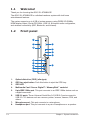
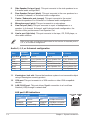
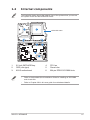
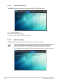
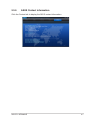
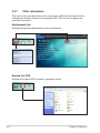
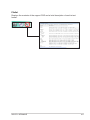
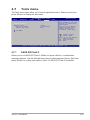
1
S1-AT5NM10E
ASUS PC (Desktop Barebone)
User Manual
E5860
First Edition
June 2010
Copyright © 2010 ASUSTeK Computer Inc. All Rights Reserved.
No part of this manual, including the products and software described in it, may be reproduced,
transmitted, transcribed, stored in a retrieval system, or translated into any language in any form or by any
means, except documentation kept by the purchaser for backup purposes, without the express written
permission of ASUSTeK Computer Inc. (“ASUS”).
Product warranty or service will not be extended if: (1) the product is repaired, modified or altered, unless
such repair, modification of alteration is authorized in writing by ASUS; or (2) the serial number of the
product is defaced or missing.
ASUS PROVIDES THIS MANUAL “AS IS” WITHOUT WARRANTY OF ANY KIND, EITHER EXPRESS
OR IMPLIED, INCLUDING BUT NOT LIMITED TO THE IMPLIED WARRANTIES OR CONDITIONS OF
MERCHANTABILITY OR FITNESS FOR A PARTICULAR PURPOSE. IN NO EVENT SHALL ASUS, ITS
DIRECTORS, OFFICERS, EMPLOYEES OR AGENTS BE LIABLE FOR ANY INDIRECT, SPECIAL,
INCIDENTAL, OR CONSEQUENTIAL DAMAGES (INCLUDING DAMAGES FOR LOSS OF PROFITS,
LOSS OF BUSINESS, LOSS OF USE OR DATA, INTERRUPTION OF BUSINESS AND THE LIKE),
EVEN IF ASUS HAS BEEN ADVISED OF THE POSSIBILITY OF SUCH DAMAGES ARISING FROM ANY
DEFECT OR ERROR IN THIS MANUAL OR PRODUCT.
SPECIFICATIONS AND INFORMATION CONTAINED IN THIS MANUAL ARE FURNISHED FOR
INFORMATIONAL USE ONLY, AND ARE SUBJECT TO CHANGE AT ANY TIME WITHOUT NOTICE,
AND SHOULD NOT BE CONSTRUED AS A COMMITMENT BY ASUS. ASUS ASSUMES NO
RESPONSIBILITY OR LIABILITY FOR ANY ERRORS OR INACCURACIES THAT MAY APPEAR IN THIS
MANUAL, INCLUDING THE PRODUCTS AND SOFTWARE DESCRIBED IN IT.
Products and corporate names appearing in this manual may or may not be registered trademarks or
copyrights of their respective companies, and are used only for identification or explanation and to the
owners’ benefit, without intent to infringe.
ii
ASUS contact information
ASUSTeK Computer Inc.
Address
Telephone Fax E-mail
Web site
Technical Support
Telephone Online support
15 Li-Te Road, Peitou, Taipei, Taiwan 11259
+886-2-2894-3447
+886-2-2890-7798
[email protected]
www.asus.com.tw
+86-21-38429911
support.asus.com
ASUS Computer International (America)
Address
Telephone Fax
Web site
Technical Support
Telephone Support fax
Online support
800 Corporate Way, Fremont, CA 94539, USA
+1-510-739-3777
+1-510-608-4555
usa.asus.com
+1-812-282-2787
+1-812-284-0883
support.asus.com
ASUS Computer GmbH (Germany and Austria)
Address
Fax
Web site
Online contact
Technical Support
Telephone (Component)
Telephone (System/Notebook/Eee/LCD)
Support Fax
Online support
Harkort Str. 21-23, D-40880 Ratingen, Germany
+49-2102-959911
www.asus.de
www.asus.de/sales
+49-1805-010923*
+49-1805-010920*
+49-2102-9599-11
support.asus.com
* EUR 0.14/minute from a German fixed landline; EUR 0.42/minute from a mobile phone.
Manufacturer:
ASUSTeK Computer Inc.
Address:
No. 150, LI-DE RD., PEITOU,
TAIPEI 112, TAIWAN
Authorised representative
in Europe:
Address:
ASUS Computer GmbH
HARKORT STR. 21-23, 40880
RATINGEN, GERMANY
iii
Table of contents
Notices.......................................................................................................... vi
Safety information...................................................................................... vii
About this guide........................................................................................ viii
System package contents............................................................................ x
Chapter 1:
Welcome!....................................................................................... 1-2
1.2
Front panel..................................................................................... 1-2
1.3
Rear panel...................................................................................... 1-3
1.4
Internal components..................................................................... 1-5
1.5
SO-DIMM Qualified Vendors List (QVL)...................................... 1-6
Chapter 2:
Starting up
2.1
Installing an operating system.................................................... 2-2
2.2
Powering up................................................................................... 2-2
2.3
Support DVD information............................................................. 2-3
2.4
2.3.1
Running the support DVD................................................ 2-3
2.3.2
Drivers menu.................................................................... 2-4
2.3.3
Utilities menu................................................................... 2-5
2.3.4
Make Disk menu.............................................................. 2-6
2.3.5
Manual menu................................................................... 2-6
2.3.6
ASUS Contact information............................................... 2-7
2.3.7
Other information............................................................. 2-8
Software information.................................................................. 2-10
2.4.1
Chapter 3:
ASUS AI Manager.......................................................... 2-10
Motherboard info
3.1
Introduction................................................................................... 3-2
3.2
Motherboard layout....................................................................... 3-2
3.3
Jumpers......................................................................................... 3-3
3.4
Connectors.................................................................................... 3-5
Chapter 4:
4.1
4.2
BIOS setup
Managing and updating your BIOS............................................. 4-2
4.1.1
ASUS Update................................................................... 4-3
4.1.2
ASUS EZ Flash 2............................................................. 4-4
4.1.3
ASUS CrashFree BIOS 3................................................. 4-5
BIOS setup program..................................................................... 4-6
4.2.1
iv
System introduction
1.1
BIOS menu screen........................................................... 4-7
Table of contents
4.3
4.4
4.5
4.6
4.7
4.8
4.2.2
Menu bar.......................................................................... 4-7
4.2.3
Navigation keys................................................................ 4-7
4.2.4
Menu items...................................................................... 4-8
4.2.5
Sub-menu items............................................................... 4-8
4.2.6
Configuration fields.......................................................... 4-8
4.2.7
Pop-up window................................................................ 4-8
4.2.8
Scroll bar.......................................................................... 4-8
4.2.9
General help.................................................................... 4-8
Main menu..................................................................................... 4-9
4.3.1
System Time.................................................................... 4-9
4.3.2
System Date.................................................................... 4-9
4.3.3
SATA1~2........................................................................ 4-10
4.3.4
Storage Configuration.....................................................4-11
4.3.5
System Information........................................................ 4-12
Advanced menu.......................................................................... 4-13
4.4.1
JumperFree.................................................................... 4-13
4.4.2
CPU Configuration......................................................... 4-14
4.4.3
Chipset........................................................................... 4-15
4.4.4
Onboard Devices Configuration..................................... 4-17
4.4.5
USB Configuration......................................................... 4-18
4.4.6
PCI PnP......................................................................... 4-19
Power menu................................................................................. 4-20
4.5.1
Suspend Mode............................................................... 4-20
4.5.2
ACPI 2.0 Support........................................................... 4-20
4.5.3
ACPI APIC Support........................................................ 4-20
4.5.4
Control Eup.................................................................... 4-20
4.5.5
APM Configuration......................................................... 4-21
4.5.6
Hardware Monitor.......................................................... 4-22
Boot menu................................................................................... 4-23
4.6.1
Boot Device Priority....................................................... 4-23
4.6.2
Boot Settings Configuration........................................... 4-24
4.6.3
Security.......................................................................... 4-25
Tools menu.................................................................................. 4-27
4.7.1
ASUS EZ Flash 2........................................................... 4-27
4.7.2
Express Gate................................................................. 4-28
4.7.3
AI NET 2........................................................................ 4-28
Exit menu..................................................................................... 4-29
Notices
Federal Communications Commission Statement
This device complies with Part 15 of the FCC Rules. Operation is subject to the
following two conditions:
•
This device may not cause harmful interference.
•
This device must accept any interference received including interference that
may cause undesired operation.
This equipment has been tested and found to comply with the limits for a
Class B digital device, pursuant to Part 15 of the FCC Rules. These limits are
designed to provide reasonable protection against harmful interference in a
residential installation. This equipment generates, uses and can radiate radio
frequency energy and, if not installed and used in accordance with manufacturer’s
instructions, may cause harmful interference to radio communications. However,
there is no guarantee that interference will not occur in a particular installation. If
this equipment does cause harmful interference to radio or television reception,
which can be determined by turning the equipment off and on, the user is
encouraged to try to correct the interference by one or more of the following
measures:
•
Reorient or relocate the receiving antenna.
•
Increase the separation between the equipment and receiver.
•
Connect the equipment to an outlet on a circuit different from that to which the
receiver is connected.
•
Consult the dealer or an experienced radio/TV technician for help.
WARNING! The use of shielded cables for connection of the monitor to the
graphics card is required to assure compliance with FCC regulations. Changes
or modifications to this unit not expressly approved by the party responsible for
compliance could void the user’s authority to operate this equipment.
Canadian Department of Communications Statement
This digital apparatus does not exceed the Class B limits for radio noise emissions
from digital apparatus set out in the Radio Interference Regulations of the
Canadian Department of Communications.
This class B digital apparatus complies with Canadian ICES-003.
REACH
Complying with the REACH (Registration, Evaluation, Authorisation, and
Restriction of Chemicals) regulatory framework, we published the chemical
substances in our products at ASUS REACH website at
http://green.asus.com/english/REACH.htm.
vi
Safety information
Electrical safety
•
To prevent electric shock hazard, disconnect the power cable from the electric outlet
before relocating the system.
•
When adding or removing devices to or from the system, ensure that the power cables
for the devices are unplugged before the signal cables are connected. If possible,
disconnect all power cables from the existing system before you add a device.
•
Before connecting or removing signal cables from the motherboard, ensure that all
power cables are unplugged.
•
Seek professional assistance before using an adapter or extension cord. These devices
could interrupt the grounding circuit.
•
Ensure that your power supply is set to the correct voltage in your area. If you are not
sure about the voltage of the electrical outlet you are using, contact your local power
company.
•
If the power supply is broken, do not try to fix it by yourself. Contact a qualified service
technician or your retailer.
Operation safety
•
Before installing the motherboard and adding devices on it, carefully read all the manuals
that came with the package.
•
Before using the product, ensure that all cables are correctly connected and the power
cables are not damaged. If you detect any damage, contact your dealer immediately.
•
To avoid short circuits, keep paper clips, screws, and staples away from connectors,
slots, sockets and circuitry.
•
Avoid dust, humidity, and temperature extremes. Do not place the product in any area
where it may becomea wet.
•
Place the product on a stable surface.
•
If you encounter technical problems with the product, contact a qualified service
technician or your retailer.
DO NOT throw the motherboard in municipal waste. This product has been
designed to enable proper reuse of parts and recycling. This symbol of the
crossed out wheeled bin indicates that the product (electrical and electronic
equipment) should not be placed in municipal waste. Check local regulations for
disposal of electronic products.
vii
DO NOT throw the mercury-containing button cell battery in municipal waste.
This symbol of the crossed out wheeled bin indicates that the battery should not
be placed in municipal waste.
CAUTION: Risk of explosion if the RTC battery is replaced by an incorrect
type. Dispose of used batteries according to the instructions.
Test Data:
•
Motherboard (ASUSTeK Computer Inc / AT5ION3L / CS6110 / DT_MB),
Power Adapter (DELTA / SADP-65KB BFJB&ADP-65JH BB F), one CPU
fan (AVC / DS05020R12HP015), one ODD (HLDS / GSA-T50N(RR07)),
one HDD (HITACHI / HDT721032SLA380).
About this guide
Audience
This guide provides general information and installation instructions about the
ASUS S1-AT5NM10E barebone system. This guide is intended for experienced
users and integrators with hardware knowledge of personal computers.
How this guide is organized
This guide contains the following parts:
1.
Chapter 1: System introduction
This chapter gives a general description of the ASUS
S1-AT5NM10E. The chapter lists the system features, including introduction
on the front and rear panel, and internal components.
2.
Chapter 2: Starting up
This chapter helps you power up the system and install drivers and utilities
from the support DVD.
3.
Chapter 3: Motherboard info
This chapter gives information about the motherboard that comes with the
system. This chapter includes the motherboard layout, jumper settings, and
connector locations.
4.
Chapter 4: BIOS setup
This chapter tells how to change system settings through the BIOS Setup
menus and describes the BIOS parameters.
viii
Conventions used in this guide
WARNING: Information to prevent injury to yourself when trying to
complete a task.
AUTION: Information to prevent damage to the components when
C
trying to complete a task.
IMPORTANT: Instructions that you MUST follow to complete a task.
NOTE: Tips and additional information to aid in completing a task.
Where to find more information
Refer to the following sources for additional information and for product and
software updates.
1.
ASUS Websites
The ASUS websites worldwide provide updated information on ASUS
hardware and software products. Refer to the ASUS contact information.
2.
Optional Documentation
Your product package may include optional documentation, such as warranty
flyers, that may have been added by your dealer. These documents are not
part of the standard package.
ix
System package contents
Check your S1-AT5NM10E system package for the following items.
If any of the items is damaged or missing, contact your retailer immediately.
Item description
1.
ASUS S1-AT5NM10E barebone system with
• ASUS motherboard
• ASUS ODD (slim type)
• ASUS chassis
• CPU fan
• Chassis fan
2.
Accessories
• SATA HDD signal cable x1
• HDD screw x4
• Power adapter x1
• Power cord x1
• ODD bezel x1
3.
Support DVD (user manual, drivers, utilities)
4.
Quick Installation Guide
This chapter gives a general description
of the ASUS S1-AT5NM10E. The
chapter lists the system features
including introduction on the front and
rear panel, and internal components.
System introduction
Chapter 1
1.1
Welcome!
Thank you for choosing the ASUS S1-AT5NM10E!
The ASUS S1-AT5NM10E is a slimline barebone system with rich home
entertainment features.
The system supports up to 4 GB of system memory using DDR3 SO-DIMMs,
HDMI display output, Serial ATA 3Gb/s, USB 3.0, 8-channel audio configuration,
and wireless connectivity (WiFi, Bluetooth, and Infrared).
1.2
Front panel
1
2
3
13
12
11
10
4
5
6
9
7
8
1-2
1.
Optical disk drive (ODD) (slim type).
2.
ODD tray eject button. Push this button to eject the ODD tray.
3.
ODD LED.
4.
Multimedia Card / Secure Digital™ / MemoryStick™ card slot.
5.
6-pin IEEE 1394a port. This port connects to an IEEE 1394a device such as
a digital camcorder.
6.
USB 3.0 ports. These Universal Serial Bus 3.0 (USB 3.0) ports connect to
USB 3.0 / 2.0 devices such as a mouse, printer, scanner, camera, PDA, and
others.
7.
Microphone port. This port connects to a microphone.
8.
Headphone port. This port connects to a pair of headphones or a speaker.
Chapter 1: System introduction
9.
Front I/O ports cover. Open this cover to show the front I/O ports.
10. Power button (with LED). Press this button to turn the system on.
11. HDD LED.
12. Network LED. This network LED is for WiFi / Bluetooth / infrared
connections.
13. Infrared (IR) port. Transfer data between the barebone system and an
infrared-enabled device using this infrared port.
1.3
Rear panel
1
5
6
7
2
3
4
8
1.
9
11
12
13
10
Chassis air vents. These vents are for ventilation inside the system chassis.
DO NOT cover the air vents, and use this system in environments with an
ambient temperature between 5ºC ~ 35ºC.
2.
DC IN port. This port connects to the DC output plug of an AC power
adapter.
3.
HDMI port. This port connects to a HDMI monitor or other HDMI compatible
devices.
4.
USB 2.0 ports. These Universal Serial Bus 2.0 (USB 2.0) ports connect
to USB 2.0 devices such as a mouse, printer, scanner, camera, PDA, and
others.
ASUS S1-AT5NM10E
1-3
5.
Side Speaker Out port (gray). This port connects to the side speakers in an
8-channel audio configuration.
6.
Rear Speaker Out port (black). This port connects to the rear speakers in a
4-channel, 6-channel, or 8-channel audio configuration.
7.
Center / Subwoofer port (orange). This port connects to the center/
subwoofer speakers in a 6-channel or 8-channel audio configuration.
8.
Microphone port (pink). This port connects to a microphone.
9.
Line Out port (lime). This port connects to a pair of headphones or a
speaker. In 4-channel, 6-channel, and 8-channel audio configuration, the
function of this port becomes Front Speaker Out.
10. Line In port (light blue). This port connects to the tape, CD, DVD player, or
other audio sources.
Refer to the audio configuration table below for the function of the audio ports in
2, 4, 6, or 8-channel configuration.
Audio 2, 4, 6, or 8-channel configuration
Port
Light Blue
Lime
Pink
Orange
Black
Gray
Headset
2-channel
Line In
Line Out
Mic In
–
–
–
4-channel
6-channel
8-channel
Line In
Front Speaker Out
Mic In
–
Rear Speaker Out
–
Line In
Front Speaker Out
Mic In
Center/Subwoofer
Rear Speaker Out
–
Line In
Front Speaker Out
Mic In
Center/Subwoofer
Rear Speaker Out
Side Speaker Out
11. Kensington® lock slot. Secure the barebone system to an immovable object
using a Kensington® security product.
12. VGA port. This port connects to a VGA monitor or other VGA compatible
devices.
13. LAN (RJ-45) port. This port allows Gigabit connection to a Local Area
Network (LAN) through a network hub.
LAN port LED indications
Activity/Link LED
Status
Description
OFF
No link
ORANGE
Linked
BLINKING
Data activity
1-4
Speed LED
Status
OFF
ORANGE
GREEN
Description
10 Mbps connection
100 Mbps connection
1 Gbps connection
ACT/LINK SPEED
LED
LED
LAN port
Chapter 1: System introduction
1.4
Internal components
The illustration below shows the internal view of the system when you remove
the system covers and the HDD/ODD holder.
2
1
HDD/ODD holder
4
3
5
AT510N3L
6
1.
3.5 inch SATA HDD bay
4.
CPU fan
2.
ODD (slim type)
5.
Chassis fan
3.
ASUS motherboard
6.
204-pin DDR3 SO-DIMM slots
•
Refer to the bundled Quick Installation Guide for installing an SO-DIMM
and a hard disk.
•
Refer to Chapter 3&4 in this user guide for motherboard details.
ASUS S1-AT5NM10E
1-5
1.5
SO-DIMM Qualified Vendors List (QVL)
DDR3 1333MHz capability
Vendor
Part No.
Size
HYNIX
HMT325S6BFR8C-H9(44NM)
2GB
DIMM support
A*
B*
•
•
DIMM support:
• A*: Supports one module inserted into either slot as Single-channel
memory configuration.
• B*: Supports one pair of modules inserted into both slots as
one pair of Dual-channel memory configuration.
Visit the ASUS website at www.asus.com for the latest QVL.
1-6
Chapter 1: System introduction
Chapter 2
Starting up
This chapter helps you power up the
system and install drivers and utilities
from the support DVD.
2.1
Installing an operating system
The barebone system supports Windows® XP/Vista/7 operating systems (OS).
Always install the latest OS version and corresponding updates so you can
maximize the features of your hardware.
2.2
•
Windows XP OS setup cannot recognize Serial ATA hard drives in AHCI
mode or in a RAID set without the necessary drivers. Use a AHCI / RAID
driver disk when installing Windows XP OS to a Serial ATA hard drive
included in AHCI mode or in a RAID set.
•
From the Windows XP setup screen, press F6 when prompted then follow
succeeding screen instructions to install the SATA drivers.
Powering up
Press the system power button ( ) to enter the OS.
Press to turn ON the system
2-2
Chapter 2: Starting up
2.3
Support DVD information
The support DVD that came with the system contains drivers and software
applications that you can install to enhance the system features.
2.3.1
•
Screen display and driver options may not be the same for different
operating system versions.
•
The contents of the support DVD are subject to change at any time without
notice. Visit the ASUS website at www.asus.com for updates.
Running the support DVD
Place the support DVD into your optical drive. If Autorun is enabled on your
computer, the DVD automatically displays the Drivers screen. Click the Drivers,
Utilities, Make Disk, Manual, and Contact tabs to display their respective menus.
Click an icon to
display support
DVD/motherboard
information
Click an item to install
If Autorun is NOT enabled on your computer, browse the contents of the support
DVD to locate the file ASSETUP.EXE from the BIN folder. Double-click the
ASSETUP.EXE to run the DVD.
ASUS S1-AT5NM10E
2-3
2.3.2
Drivers menu
The Drivers menu shows the available device drivers if the system detects installed
devices. Install the necessary drivers to activate the devices.
ASUS InstAll
Installs all of the drivers through an installation wizard.
Intel Chipset Driver
Installs the Intel® chipset driver.
Realtek Audio Driver
Installs the Realtek® audio driver and application.
Wireless LAN and Bluetooth Driver
Installs the wireless LAN and Bluetooth driver.
Realtek 10/100/1000 PCI-E LAN Driver
Installs the Realtek® 10/100/1000 PCI-E LAN driver.
USB 3.0 Host Controller Driver
Installs the USB 3.0 host controller driver.
NVIDIA ION Graphics Driver
Installs the NVIDIA® ION graphics driver.
CIR Tool Kit
Installs the CIR (Consumer Infrared) tool kit.
Intel Matrix Storage Manager Driver
Installs the Intel® Matrix Storage Manager driver.
2-4
Chapter 2: Starting up
2.3.3
Utilities menu
The Utilities menu shows the applications and other software that the motherboard
supports.
ASUS InstAll
Installs all of the utilities through an installation wizard.
ASUS Update
Allows you to download the latest version of the BIOS from the ASUS website.
ASUS AI Manager
Installs the ASUS AI Manager.
ASUS Express Gate Installer
Installs the ASUS Express Gate.
Realtek Ethernet Utility
Installs the Realtek® Ethernet utility.
Adobe Reader 9
Installs the Adobe® Reader that allows you to open, view, and print documents in
Portable Document Format (PDF).
Internet Radio
installs the Internet Radio utility.
PC-cillin 2010
Installs the PC-cillin utility.
ASUS S1-AT5NM10E
2-5
2.3.4
Make Disk menu
The Make Disk menu allows you to make a AHCI/RAID driver disk.
Intel AHCI/RAID Driver
Creates an Intel® AHCI / RAID driver disk.
2.3.5
Manual menu
The Manual menu contains a list of supplementary user manuals.
The user manual files are in Portable Document Format (PDF). Install the
Adobe® Reader from the Utilities menu before opening a user manual file.
2-6
Chapter 2: Starting up
2.3.6
ASUS Contact information
Click the Contact tab to display the ASUS contact information.
ASUS S1-AT5NM10E
2-7
2.3.7
Other information
The icons on the top right corner of the screen give additional information on the
motherboard and the contents of the support DVD. Click an icon to display the
specified information.
Motherboard Info
Displays the general specifications of the motherboard.
Browse this DVD
Displays the support DVD contents in graphical format.
2-8
Chapter 2: Starting up
Filelist
Displays the contents of the support DVD and a brief description of each in text
format.
ASUS S1-AT5NM10E
2-9
2.4
Software information
Most of the applications in the support DVD have wizards that will conveniently
guide you through the installation. View the online help or readme file that came
with the software for more information.
2.4.1
ASUS AI Manager
ASUS AI Manager is a utility which gives you quick and easy access to frequentlyused applications.
Installing AI Manager
To install AI Manager on your computer:
1.
Place the support CD in the optical drive. If Autorun is enabled, the Drivers
installation wizard appears.
If Autorun is not enabled in your computer, locate the setup.exe file from the
ASUS AI Manager folder in the support CD. Double-click the setup.exe file to
start installation.
2.
Click the Utilities tab, then click ASUS AI Manager.
3.
Follow the screen instructions to complete the installation.
Launching AI Manager
To launch the AI Manager from the Windows® desktop, click Start > All Programs
> ASUS > AI Manager 1.xx.xx > AI Manager. The AI Manager quick bar appears
on the desktop.
After launching the application, the AI Manager icon
appears in the Windows® taskbar.
Right-click this icon to switch between quick
bar and main window, and to launch the
AI Manager either from the quick bar or
taskbar.
2-10
Chapter 2: Starting up
AI Manager quick bar
The AI Manager quick bar saves the desktop space and allows you to launch
the ASUS utilities or display system information easily. Click any of the Main, My
Favorites, Support or Information tab to display the menu’s contents.
Close button
Maximize / restore button
Minimize button
Main
Support
My Favorites
Information
Click the Maximize/restore button
to switch between full window and quick
bar. Click the Minimize button
to keep the AI Manager on the taskbar. Click the
Close button
to quit the AI Manager.
Main
The Main menu contains five utilities: AI Disk, AI Security, AI Booting, and AI
Probe. Click the arrow on the Main menu icon to browse through the utilities in the
main menu.
Click to extend or restore
Click to display
items on the right
Click to display
items on the left
AI Disk
AI Disk allows you to easily clear temporary IE files, IE cookies, IE URLs, IE
history, or the Recycle Bin. Click the AI Disk icon on the quick bar to display
the full AI Disk window and select the items you want to clear. Click Apply
when done.
ASUS S1-AT5NM10E
2-11
AI Security
AI Security enables you to set a password to secure your devices, such as
USB flash disks and CD/DVD disks, from unauthorized access.
2-12
To lock a device:
1. When using AI Security for the first time, you are asked to set a password. Enter a password with at most 20 alphanumeric characters.
2. Confirm the password.
3. Key in the password hint (recommended).
4. When done, click Ok.
5. Select the device you want to lock, then click Apply.
6. Key in the password you have set previously, then click Ok. The selected device is locked and not accessible.
To unlock the selected device:
1. Uncheck the checkbox of the selected device, then click Apply.
2. Key in the password you have set previously, then click Ok. The selected device is unlocked.
To change password:
Click Change Password, then follow the on-screen instructions to change
the password.
Chapter 2: Starting up
AI Booting
AI Booting allows you to specify the boot device priority sequence.
To specify the boot sequence:
1. Select a device, then click on the left/right button to specify the boot sequence.
2. When done, press Apply.
AI Probe
AI Probe automatically detects and displays the motherboard and CPU
temperatures, CPU fan speed, and the voltage output. You can adjust the
values as you need.
Click the Temperature, Voltage, or Fan Speed tab, then select an item to
enable and change the value by dragging the bar.
ASUS S1-AT5NM10E
2-13
My Favorites
My Favorites allows you to add applications that you frequently use, saving you
from searching for the applications throughout your computer.
To add an application:
1.
Click Add, then locate the application you want to add to My Favorites.
2.
Click Open on the file location window. The application is added to My
Favorites list.
Right click on the application icon to launch, delete, or rename the selected
application. You can also double click to launch the selected application.
2-14
Chapter 2: Starting up
Support
Click any links on the Support window to go to the ASUS website, technical
support website, download support website, or contact information.
Information
Click the tab on the Information window to see the detailed information about your
system, motherboard, CPU, BIOS, installed device(s), and memory.
ASUS S1-AT5NM10E
2-15
2-16
Chapter 2: Starting up
This chapter gives information about
he motherboard that comes with the
system. This chapter includes the
motherboard layout, jumper settings,
and connector locations.
Motherboard info
Chapter 3
3.1
Introduction
The barebone system comes with an ASUS motherboard. This chapter provides
technical information about the motherboard for future upgrades or system
reconfiguration.
3.2
Motherboard layout
23.1cm(9.1in)
AUDIO
LAN1_
USB12
ALC
887
USB34
VGA_HDMI
DC_PWR
USBPW1-4
HDD_PWR
RTL
8111E
CPU_FAN
SPDIF_OUT
Intel®
Atom D510
VT6308P
NVIDIA®
ION
DEBUG
Lithium Cell
CMOS Power
CHA_FAN
Intel®
NM10
8MB
BIOS
AT5I0N3L
CLRTC
SB_PWR
DIMM1
USBPW56
ICS
954-A4
SATA1
JMB360
SATA2
3-2
MIC_IN
ESATA_
USB56
CARD_READER
E1394
DIMM2
Super
I/O
BUZZER
LINE_OUT
17.8cm(7in)
WLAN
PWR_SW
CIR_J
LED_PANEL
Chapter 3: Motherboard info
3.3
1.
Jumpers
Clear RTC RAM (3-pin CLRTC)
This jumper allows you to clear the Real Time Clock (RTC) RAM in
CMOS. You can clear the CMOS memory of date, time, and system setup
parameters by erasing the CMOS RTC RAM data. The onboard button
cell battery powers the RAM data in CMOS, which include system setup
information such as system passwords.
CLRTC
2
2
Normal
(Default)
Clear RTC
1
3
AT5I0N3L
AT5I0N3L Clear RTC RAM
To erase the RTC RAM:
1. Turn OFF the computer and unplug the power cord.
2. Move the jumper cap from pins 1-2 (default) to pins 2-3. Keep the cap
on pins 2-3 for about 5-10 seconds, then move the cap back to pins 1-2.
3. Plug the power cord and turn ON the computer.
4. Hold down the <Del> key during the boot process and enter BIOS setup
to re-enter data.
Except when clearing the RTC RAM, never remove the cap on CLRTC jumper
default position. Removing the cap will cause system boot failure!
•
If the steps above do not help, remove the onboard battery and move the
jumper again to clear the CMOS RTC RAM data. After clearing the CMOS,
reinstall the battery.
•
You do not need to clear the RTC when the system hangs due to
overclocking. For system failure due to overclocking, use the CPU
Parameter Recall (C.P.R.) feature. Shut down and reboot the system, then
the BIOS automatically resets parameter settings to default values.
ASUS S1-AT5NM10E
3-3
2.
USB device wake-up (3-pin USBPW1-4, USBPW56)
Set these jumpers to +5V to wake up the computer from S1 sleep mode
(CPU stopped, DRAM refreshed, system running in low power mode) using
the connected USB devices. Set these jumpers to +5VSB to wake up the
compurer from S3 and S4 sleep modes (no power to CPU, DRAM in slow
refresh, power supply in reduced power mode).
USBPW1-4
1
2
+5V
2 3
+5VSB
(Default)
USBPW56
AT5I0N3L
1
2
+5V
(Default)
2 3
+5VSB
AT5I0N3L USB Device Wake Up
3-4
Chapter 3: Motherboard info
3.4
1.
Connectors
Serial ATA connectors (7-pin SATA1, SATA2)
These connectors are for the Serial ATA signal cables for Serial ATA hard disk
and optical disk drives.
SATA1
GND
RSATA_TXP1
RSATA_TXN1
GND
RSATA_RXP1
RSATA_RXN1
GND
SATA2
AT5I0N3L
GND
RSATA_TXP2
RSATA_TXN2
GND
RSATA_RXP2
RSATA_RXN2
GND
AT5I0N3L SATA connectors
Install the Windows® XP Service Pack 2 or later version before using Serial ATA.
2.CPU and chassis fan connectors (4-pin CPU_FAN, 4-pin CHA_FAN)
Connect the fan cables to the fan connectors on the motherboard, ensuring
that the black wire of each cable matches the ground pin of the connector.
CPU_FAN
GND
CPU FAN PWR
CPU FAN IN
CPU FAN PWM
AT5I0N3L
AT5I0N3L fan connectors
CHA_FAN
GND
CPU FAN PWR
CPU FAN IN
CPU FAN PWM
DO NOT forget to connect the fan cables to the fan connectors. Insufficient air
flow inside the system may damage the motherboard components. These are
not jumpers! DO NOT place jumper caps on the fan connectors!
ASUS S1-AT5NM10E
3-5
3.
SATA power connector (5-pin HDD_PWR)
Connect the supplied SATA power cable splitter to this connector to power
one optical disk drive and one hard disk drive.
HDD_PWR
AT5I0N3L
+5V
GND
+3V
GND
+12V
AT5I0N3L SATA power connector
3-6
Chapter 3: Motherboard info
Chapter 4
BIOS setup
This chapter tells how to change
system settings through the BIOS
Setup menus and describes the BIOS
parameters.
4.1
Managing and updating your BIOS
BIOS (Basic Input and Output System) stores system settings such as storage
device configuration, overclocking settings, advanced power management, and
boot device configuration that are needed for system startup in the motherboard
CMOS. In normal circumstances, the default BIOS settings apply to most
conditions to ensure optimum performance. DO NOT change the default BIOS
settings except in the following circumstances:
4-2
•
An error message appears on the screen during the system startup and
requests you to run the BIOS setup.
•
You have installed a new system component that requires further BIOS
settings or update.
•
Inappropriate BIOS settings may result to system instability or boot failure.
We strongly recommend that you change the BIOS settings with the help of
a trained service personnel.
•
BIOS updating is potentially risky. If there is no problem in using the current
BIOS version, DO NOT manually update the BIOS. Inappropriate BIOS
updating may result to system boot failure.
•
Save a copy of the original motherboard BIOS file to a USB flash disk
in case you need to restore the BIOS in the future. Copy the original
motherboard BIOS using the ASUS Update utility.
•
Download the latest BIOS file from the ASUS website at www.asus.com.
Chapter 4: BIOS setup
4.1.1
ASUS Update
ASUS Update is a utility that allows you to manage, save, and update the
motherboard BIOS in Windows® environment.
ASUS Update requires an Internet connection either through a network or an
Internet Service Provider (ISP).
Installing ASUS Update
To install ASUS Update:
1.
Place the support DVD in the optical drive. The Drivers menu appears.
2.
Click the Utilities tab, then click ASUS Update.
3.
Follow the onscreen instructions to complete the installation.
Quit all Windows® applications before you update the BIOS using this utility.
Updating the BIOS
To update the BIOS:
1.
From the Windows® desktop, click Start > Programs > ASUS >
ASUSUpdate > ASUSUpdate to launch the ASUS Update utility.
2.
From the dropdown list, select any of the updating process:
Updating from the Internet
a. Select Update BIOS from the Internet, then click Next.
b.Select the ASUS FTP site nearest you to avoid network traffic, or click
Auto Select then click Next.
c.From the FTP site, select the BIOS version that you want to download
then click Next.
ASUS Update is capable of updating itself through the Internet. Always update
the utility to avail all its features.
3.
Updating from a BIOS file
a. Select Update BIOS from a file, then click Next.
b. Locate the BIOS file from the Open window, then click Open.
Follow the onscreen instructions to complete the updating process.
ASUS S1-AT5NM10E
4-3
4.1.2
ASUS EZ Flash 2
The ASUS EZ Flash 2 feature allows you to update the BIOS without using an
OS‑based utility.
Before you start using this utility, download the latest BIOS file from the ASUS
website at www.asus.com.
To update the BIOS using EZ Flash 2:
1.
Insert the USB flash disk that contains the latest BIOS file to the USB port,
then launch EZ Flash 2 in any of these two ways:
•
•Enter the BIOS setup. Go to the Tools menu, select EZ Flash 2, and
press <Enter> to enable it.
2.
Press <Tab> to switch between drives until the correct BIOS file is found,
then press <Enter>. EZ Flash 2 performs the BIOS updating process and
automatically reboots the system when done.
Press <Alt> + <F2> during POST.
ASUSTek
BIOS ROM
ROMUtility
Utility
V3.44
ASUSTek EZ
EZ Flash
Flash 2 BIOS
V3.36
FLASH TYPE: MXIC 25L8005
Current ROM
Update ROM
BOARD: S1-AT5NM10E
BOARD: Unknown
VER: 0103 (H:00 B:02)
VER: Unknown
DATE: 04/06/2010
DATE: Unknown
PATH: A:\
A:
Note
[Enter] Select or Load
[Up/Down/Home/End] Move
4-4
[Tab] Switch
[B] Backup
[V] Drive Info
[ESC] Exit
•
This function supports USB flash disks with FAT 32/16 format and single
partition only.
•
DO NOT shut down or reset the system while updating the BIOS to prevent
system boot failure!
Chapter 4: BIOS setup
4.1.3
ASUS CrashFree BIOS 3
The ASUS CrashFree BIOS 3 is an auto recovery tool that allows you to restore
the BIOS file when it fails or gets corrupted during the updating process. You can
update a corrupted BIOS file using the motherboard support DVD or a USB flash
disk that contains the updated BIOS file.
•
Ensure that you rename the BIOS file in the USB flash disk to
AT5NM10E.ROM.
•
Prepare the motherboard support DVD or the USB flash disk containing the
updated motherboard BIOS before using this utility.
Recovering the BIOS
To recover the BIOS:
1.
Turn on the system.
2.
Insert the support DVD or USB flash disk with the BIOS file to the optical
drive or USB port.
3.
The utility automatically checks the devices for the BIOS file. When the BIOS
file is found, the utility reads and starts flashing the corrupt BIOS file.
4.
Turn off the system after the utility completes the updating process and turn it
on again.
DO NOT shut down or reset the system while updating the BIOS! Doing so can
cause system boot failure!
ASUS S1-AT5NM10E
4-5
4.2
BIOS setup program
Use the BIOS Setup program to update the BIOS or configure its parameters. The
BIOS screens include navigation keys and brief online help to guide you in using
the BIOS Setup program.
Entering BIOS Setup at startup
To enter BIOS Setup at startup:
•
Press <Delete> during the Power-On Self-Test (POST). If you do not press
<Delete>, POST continues with its routines.
Entering BIOS Setup after POST
To enter BIOS Setup after POST, do any of the following:
•
Press <Ctrl> + <Alt> + <Delete> simultaneously.
•
Press the reset button on the system chassis.
•
Press the power button to turn the system off then turn it back on. Do this
option only if you failed to enter BIOS Setup using the first two options.
Using the power button, reset button, or the <Ctrl>+<Alt>+<Del> keys to
force reset from a running operating system can cause damage to your data
or system. We recommend to always shut-down the system properly from the
operating system.
4-6
•
The default BIOS settings for this motherboard apply for most conditions
to ensure optimum performance. If the system becomes unstable after
changing any BIOS settings, load the default settings to ensure system
compatibility and stability. Select the Load Default Settings item under the
Exit Menu. See section 4.8 Exit Menu.
•
The BIOS setup screens shown in this section are for reference purposes
only, and may not exactly match what you see on your screen.
•
Visit the ASUS website at www.asus.com to download the latest BIOS file
for this motherboard.
Chapter 4: BIOS setup
4.2.1
BIOS menu screen
Menu items
Main
Menu bar
Advanced
System Time
System Date
SATA 1
SATA 2 Power
Configuration fields
General help
S1-AT5NM10E BIOS Setup
Boot
Tools
Exit
[14:32:36]
[Fri 06/25/2010]
:[Not Detected]
:[Not Detected]
Version 0103
Use [ENTER], [TAB]
or [SHIFT-TAB] to
select a field.
Use [+] or [-] to
configure system time.
Storage Configuration System Information
Enter
F1
F10
ESC
Select Screen
Select Item
Go to Sub-screen
General Help
Save and Exit
Exit
v02.61 (C)Copyright 1985-2010, American Megatrends, Inc.
Sub-menu items
4.2.2
Navigation keys
Menu bar
The menu bar on top of the screen has the following main items:
Main
For changing the basic system configuration
Advanced
For changing the advanced system settings
Power
For changing the advanced power management (APM)
configuration
Boot
For changing the system boot configuration
Tools
For configuring options for special functions
Exit
For selecting the exit options and loading default settings
To select an item on the menu bar, press the right or left arrow key on the keyboard
until the desired item is highlighted.
4.2.3
Navigation keys
At the bottom right corner of a menu screen are the navigation keys for that
particular menu. Use the navigation keys to select items in the menu and change
the settings.
Some of the navigation keys differ from one screen to another.
ASUS S1-AT5NM10E
4-7
4.2.4
Menu items
The highlighted item on the menu bar
displays the specific items for that
menu. For example, selecting Main
shows the Main menu items.
Main
S1-AT5NM10E BIOS Setup
Boot
Tools
Exit
Power
[14:32:36]
[Fri 06/25/2010]
:[Not Detected]
:[Not Detected]
Version 0103
Use [ENTER], [TAB]
or [SHIFT-TAB] to
select a field.
Use [+] or [-] to
configure system time.
Storage Configuration System Information
Select Screen
Select Item
Enter Go to Sub-screen
F1
General Help
F10
Save and Exit
ESC
Exit
The other items (Advanced, Power,
Boot, Tool, and Exit) on the menu bar
have their respective menu items.
4.2.5
Advanced
System Time
System Date
SATA 1
SATA 2 v02.61 (C)Copyright 1985-2010, American Megatrends, Inc.
Main menu items
Sub-menu items
A solid triangle before each item on any menu screen means that the iteam has a
sub-menu. To display the sub-menu, select the item and press <Enter>.
4.2.6
Configuration fields
These fields show the values for the menu items. If an item is user- configurable,
you can change the value of the field opposite the item. You cannot select an item
that is not user-configurable.
A configurable field is enclosed in brackets, and is highlighted when selected. To
change the value of a field, select it then press <Enter> to display a list of options.
Refer to 4.2.7 Pop-up window.
4.2.7
Pop-up window
Select a menu item then press
<Enter> to display a pop-up window
with the configuration options for that
item.
4.2.8
Scroll bar
Main
Advanced
Power
S1-AT5NM10E BIOS Setup
Boot
Tools
Exit
SATA 1
Device
: Not Detected
Type
[Auto]
LBA/Large Mode
[Auto]
Options
Block(Multi-Sector Transfer) M [Auto]
Auto [Auto]
PIO Mode
CDROM
DMA Mode
ARMD [Auto]
Not Installed
SMART Monitoring
[Auto]
32Bit Data Transfer
[Enabled]
Version 0103
Select the type of
device connected to
the system.
Select Screen
Select Item
Enter Go to Sub-screen
F1
General Help
F10
Save and Exit
ESC
Exit
v02.61 (C)Copyright 1985-2010, American Megatrends, Inc.
A scroll bar appears on the right side
Pop-up window
of a menu screen when there are
items that do not fit on the screen.
Press the
Up/Down arrow keys or <Page Up> /<Page Down> keys to display the other items
on the screen.
4.2.9
General help
At the top right corner of the menu screen is a brief description of the selected
item.
4-8
Chapter 4: BIOS setup
4.3
Main menu
When you enter the BIOS Setup program, the Main menu screen appears, giving
you an overview of the basic system information.
Refer to section 4.2.1 BIOS menu screen for information on the menu screen
items and how to navigate through them.
Main
Advanced
System Time
System Date
SATA 1
SATA 2 Power
S1-AT5NM10E BIOS Setup
Boot
Tools
Exit
[14:32:36]
[Fri 06/25/2010]
:[Not Detected]
:[Not Detected]
Version 0103
Use [ENTER], [TAB]
or [SHIFT-TAB] to
select a field.
Use [+] or [-] to
configure system time.
Storage Configuration System Information
Enter
F1
F10
ESC
Select Screen
Select Item
Go to Sub-screen
General Help
Save and Exit
Exit
v02.61 (C)Copyright 1985-2010, American Megatrends, Inc.
4.3.1
System Time [xx:xx:xx]
Allows you to set the system time.
4.3.2
System Date [Day xx/xx/xxxx]
Allows you to set the system date.
ASUS S1-AT5NM10E
4-9
4.3.3
SATA1~2
While entering Setup, the BIOS automatically detects the presence of SATA
devices. There is a separate sub-menu for each SATA device. Select a device item
then press <Enter> to display the SATA device information.
Main
Advanced
Power
S1-AT5NM10E BIOS Setup
Boot
Tools
Exit
Version 0103
Select the type of
SATA 1
Device
: Not Detected
Type
[Auto]
LBA/Large Mode
[Auto]
Block(Multi-Sector Transfer) M [Auto]
PIO Mode
[Auto]
DMA Mode
[Auto]
SMART Monitoring
[Auto]
32Bit Data Transfer
[Enabled]
device connected
Select
the typeto
the system.
of device connected
Enter
F1
F10
ESC
Select Screen
Select Item
Go to Sub-screen
General Help
Save and Exit
Exit
v02.61 (C)Copyright 1985-2010, American Megatrends, Inc.
The BIOS automatically detects the values opposite the dimmed items (Device,
Vendor, Size, LBA Mode, Block Mode, PIO Mode, Async DMA, Ultra DMA, and
SMART monitoring). These values are not user-configurable. These items show
N/A if no SATA device is installed in the system.
Type [Auto]
Allows you to select the type of device connected to the system.
Configuration options: [Auto] [CDROM] [ARMD] [Not Installed]
LBA/Large Mode [Auto]
Enables or disables the LBA mode. Setting to Auto enables the LBA mode if the
device supports this mode, and if the device was not previously formatted with LBA
mode disabled. Configuration options: [Disabled] [Auto]
Block (Multi-sector Transfer) M [Auto]
Enables or disables data multi-sectors transfers. When set to Auto, the data
transfer from and to the device occurs multiple sectors at a time if the device
supports multi-sector transfer feature. When set to [Disabled], the data transfer
from and to the device occurs one sector at a time.
Configuration options: [Disabled] [Auto]
PIO Mode [Auto]
Selects the PIO mode. Configuration options: [Auto] [0] [1] [2] [3] [4]
4-10
Chapter 4: BIOS setup
DMA Mode [Auto]
Selects the DMA mode. Configuration options: [Auto]
SMART Monitoring [Auto]
Sets the Smart Monitoring, Analysis, and Reporting Technology.
Configuration options: [Auto] [Disabled] [Enabled]
32Bit Data Transfer [Enabled]
Enables or disables 32-bit data transfer.
Configuration options: [Disabled] [Enabled]
4.3.4
Storage Configuration
The items in this menu allow you to set or change the configurations for the SATA
devices installed in the system. Select an item then press <Enter> if you want to
configure the item.
S1-AT5NM10E BIOS Setup
Main
Options
Storage Configuration
Configure SATA as
SATA Run Mode Configuration
Version 0103
[IDE]
[Compatible]
Select the type
ofIDE
device conAHCI
Disabled
nected
Enter
F1
F10
ESC
Select Screen
Select Item
Go to Sub-screen
General Help
Save and Exit
Exit
v02.61 (C)Copyright 1985-2010, American Megatrends, Inc.
Configure SATA as [IDE]
Sets the configuration for the Serial ATA connectors. Configuration options: [IDE]
[AHCI] [Disabled]
SATA Run Mode Configuration [Compatible]
Sets the SATA run mode configuration. Configuration options: [Compatible]
[Enhanced]
ASUS S1-AT5NM10E
4-11
4.3.5
System Information
This menu gives you an overview of the general system specifications. The BIOS
automatically detects the items in this menu.
S1-AT5NM10E BIOS Setup
Main
Select the type
of device connected
BIOS Information
Version
: 0103
Build Date : 04/06/10
Processor
Type
Speed
: Intel(R) Atom(TM)2 CPU
: 1666MHz
Version 0103
D510 @ 1.66GHz
System Memory
Installed Size: 2048MB
Usable Size
: 2048MB
Enter
F1
F10
ESC
Select Screen
Select Item
Go to Sub-screen
General Help
Save and Exit
Exit
v02.61 (C)Copyright 1985-2010, American Megatrends, Inc.
BIOS Information
Displays the auto-detected BIOS information.
Processor
Displays the auto-detected CPU specification.
System Memory
Displays the auto-detected system memory.
4-12
Chapter 4: BIOS setup
4.4
Advanced menu
The Advanced menu items allow you to change the settings for the CPU and other
system devices.
Be cautious when changing the settings of the Advanced menu items. Incorrect
field values can cause the system to malfunction.
Main
Advanced
Power
S1-AT5NM10E BIOS Setup
Boot
Tools
Exit
Version 0103
JumperFree
CPU Configuration
Chipset
Onboard Devices Configuration
USB Configuration
PCIPnP
Enter
Enter
F1
F1
F10
F10
ESC
ESC
Select
Select Screen
Screen
Select
Select Item
Item
Go
Screen
Go to
to Sub
Sub-screen
General
General Help
Help
Save
Save and
and Exit
Exit
Exit
Exit
v02.61 (C)Copyright 1985-2010, American Megatrends, Inc.
4.4.1
JumperFree
The items in this menu allows you to adjust the system frequency/voltage.
Advanced
S1-AT5NM10E BIOS Setup
AI Overclocking
[Auto]
Vcore Over Voltage
Memory Over Voltage
1.5V Over Voltage
[Disabled]
[Auto]
[Auto]
Version 0103
Select the target CPU
frequency, and the
relevant parameters
will be auto-adjusted.
Frequencies higher
than CPU manufacturer
recommends are not
guaranteed to be
stable. If the system
becomes unstable,
return to the default.
Enter
+-
F1
F1
F10
F10
ESC
ESC
Select Screen
Select Item
Go to Sub-screen
Change
Option
General Help
Save and Exit
Exit
v02.61 (C)Copyright 1985-2010, American Megatrends, Inc.
AI Overclocking [Auto]
Allows selection of CPU overclocking options to achieve desired CPU internal
frequency. Select either one of the preset overclocking configuration options:
Manual - allows you to individually set overclocking parameters.
Auto - loads the optimal settings for the system.
ASUS S1-AT5NM10E
4-13
The following item appears only when you set AI Overclocking to [Manual].
CPU Frequency [xxx]
Displays the frequency sent by the clock generator to the system bus and
PCI bus. The value of this item is auto-detected by the BIOS. Use the <+>
and <-> keys to adjust the CPU frequency. You can also type the desired
CPU frequency using the numeric keypad. The values range from 150 to 250.
Vcore Over Voltage [Disabled]
Sets the Vcore over voltage. Selecting [Disabled] sets the Vcore over voltage to
the default value. Selecting [Enabled] sets the Vcore over voltage to +50mV.
Configuration options: [Enabled] [Disabled]
Memory Over Voltage [Auto]
Sets the memory over voltage. The value ranges from 1.5000V to 1.9000V with a
0.0500V increment. Key in the value directly or use +/- to adjust the voltage.
1.5V Over Voltage [Auto]
Sets the 1.5V over voltage. The values range from 1.5000V to 1.6500V with a
0.0500V increment. Key in the value directly or use +/- to adjust the voltage.
4.4.2
CPU Configuration
The items in this menu show the CPU-related information that the BIOS
automatically detects.
Advanced
S1-AT5NM10E BIOS Setup
Version 0103
Disabled for WindowsXP
Configure advanced CPU settings
Module Version:3F.17
Manufacturer:Intel
Brand String:Intel(R) Atom(TM) CPU D510 @ 1.66GHz
Frequency
:1.66GHz
FSB Speed
:666MHz
Cache L1
:48 KB
Cache L2
:1024 KB
Ratio Actual Value :10
Max CPUID Value Limit
CPU TM Function
Execute-Disable Bit Capability
Hyper Threading Technology
[Disabled]
[Enabled]
[Enabled]
[Enabled]
Enter
+-
F1
F1
F10
F10
ESC
ESC
Select Screen
Select Item
Go to Sub-screen
Change
Option
General Help
Save and Exit
Exit
v02.61 (C)Copyright 1985-2010, American Megatrends, Inc.
4-14
Chapter 4: BIOS setup
Max CPUID Value Limit [Disabled]
Allows you to determine whether to limit CPUID maximum value. Set this item to
[Disabled] for Windows XP operating system; set this item to [Enabled] for legacy
operating system such as Windows NT4.0. (Default: Disabled)
Configuration options: [Disabled] [Enabled]
CPU TM Function [Enabled]
Enables or disables Intel® CPU Thermal Monitor (TM) function, a CPU overheating
protection function. When enabled, the CPU core frequency and voltage are
reduced when the CPU overheats. Configuration options: [Disabled] [Enabled]
Execute-Disable Bit Capability [Enabled]
Enables or disables Intel® Execute Disable Bit function. This function enhance
protection of your computer, reducing exposure to viruses and malicious
buffer overflow attacks when working with its supporting software and system.
Configuration options: [Disabled] [Enabled]
Hyper Threading Technology [Enabled]
Allows you to enable or disable the Intel® Hyper Threading technology.
Configuration options: [Disabled] [Enabled]
4.4.3
Chipset
The Chipset menu allows you to change the advanced chipset settings. Select an
item then press <Enter> to display the sub-menu.
Advanced
S1-AT5NM10E BIOS Setup
Advanced Chipset Settings
Version 0103
Configure North Bridge
features.
WARNING: Setting wrong values in below sections may
cause system to malfunction.
North Bridge Configuration
Enter
+-
F1
F1
F10
F10
ESC
ESC
Select Screen
Select Item
Go to Sub-screen
Change
Option
General Help
Save and Exit
Exit
v02.61 (C)Copyright 1985-2010, American Megatrends, Inc.
ASUS S1-AT5NM10E
4-15
North Bridge Configuration
Advanced
S1-AT5NM10E BIOS Setup
Version 0103
North Bridge Chipset Configuration
DRAM Frequency
Configure DRAM Timing by SPD
[Auto]
[Enabled]
Initiate Graphic Adapter
[PCI/IGD]
Options
Auto
667 MHz
800 MHz
Enter
+-
F1
F1
F10
F10
ESC
ESC
Select Screen
Select Item
Go to Sub-screen
Change
Option
General Help
Save and Exit
Exit
v02.61 (C)Copyright 1985-2010, American Megatrends, Inc.
DRAM Frequency [Auto]
Allows you to set the DDR3 operating frequency. Configuration options: [Auto]
[667MHz] [800MHz]
Configure DRAM Timing by SPD [Enabled]
Allows you to enable or disable configuring the DRAM Timing by SPD.
Configuration options: [Enabled] [Disabled]
Initiate Graphic Adapter [PCI/IGD]
Allows you to decide which graphics controller to use as the primary boot device.
Configuration options: [IGD] [PCI/IGD]
4-16
Chapter 4: BIOS setup
4.4.4
Onboard Devices Configuration
Advanced
S1-AT5NM10E BIOS Setup
Onboard Devices Configuration
Onboard LAN
Onboard LAN Boot ROM
Audio Controller
Front Panel Support Type
Onboard Wlan
Onboard Bluetooth
CIR Function
VT6308P Controller
Version 0103
Enable / Disable
Onboard Lan.
[Enabled]
[Disabled]
[Enabled]
[HD Audio]
[Enabled]
[Enabled]
[Enabled]
[Enabled]
Enter
+-
F1
F1
F10
F10
ESC
ESC
Select Screen
Select Item
Go to Sub-screen
Change
Option
General Help
Save and Exit
Exit
v02.61 (C)Copyright 1985-2010, American Megatrends, Inc.
Onboard LAN [Enabled]
Allows you to enable or disable the onboard LAN controller.
Configuration options: [Enabled] [Disabled]
Onboard LAN Boot ROM [Disabled]
Allows you to enable or disable the boot ROM in the onboard LAN controller.
This item appears only when the Onboard LAN item is set to Enabled.
Configuration options: [Disabled] [Enabled]
Audio Controller [Enabled]
Allows you to enable or disable the onboard audio controller.
Configuration options: [Enabled] [Disabled]
Front Panel Support Type [HD Audio]
Allows you to select the front panel audio type.
Configuration options: [AC97] [HD Audio]
Onboard WLan [Enabled]
Allows you to enable or disable the onboard WLAN controller.
Configuration options: [Enabled] [Disabled]
Onboard Bluetooth [Enabled]
Allows you to enable or disable the Bluetooth function.
Configuration options: [Enabled] [Disabled]
CIR Function [Enabled]
Allows you to enable or disable the infrared function.
Configuration options: [Enabled] [Disabled]
VT6308P Controller [Enabled]
Allows you to enable or disable the 1394 controller.
Configuration options: [Enabled] [Disabled]
ASUS S1-AT5NM10E
4-17
4.4.5
USB Configuration
The items in this menu allows you to change the USB-related features. Select an
item then press <Enter> to display the configuration options.
Advanced
S1-AT5NM10E BIOS Setup
Version 0103
USB Configuration
Options
Module Version - 2.24.5-14.4
Disabled
Enabled
USB Devices Enabled:
1 Keyboard, 1 Hub
USB Functions
USB 2.0 Controller
Legacy USB Support
USB 2.0 Controller Mode
[Enabled]
[Enabled]
[Auto]
[HiSpeed]
Enter
+-
F1
F1
F10
F10
ESC
ESC
Select Screen
Select Item
Go to Sub-screen
Change
Option
General Help
Save and Exit
Exit
v02.61 (C)Copyright 1985-2010, American Megatrends, Inc.
The Module Version and USB Devices Enabled items show the
auto-detected values. If no USB device is detected, the item shows None.
USB Functions [Enabled]
Allows you to enable or disable the USB functions.
Configuration options: [Disabled] [Enabled]
USB 2.0 Controller [Enabled]
Allows you to enable or disable USB 2.0 controller.
Configuration options: [Enabled] [Disabled]
Legacy USB Support [Auto]
Allows you to enable or disable support for USB devices on legacy operating
systems (OS). Setting to Auto allows the system to detect the presence of USB
devices at startup. If detected, the USB controller legacy mode is enabled. If no
USB device is detected, the legacy USB support is disabled.
Configuration options: [Disabled] [Enabled] [Auto]
USB 2.0 Controller Mode [HiSpeed]
Allows you to configure the USB 2.0 controller in HiSpeed (480Mbps) or Full
Speed (12Mbps). Configuration options: [FullSpeed] [HiSpeed]
4-18
Chapter 4: BIOS setup
The following items may only appear when a USB storage device is plugged.
USB Mass Storage Device Configuration
USB Mass Storage Reset Delay [20 Sec]
Allows you to set the maximum time that the BIOS waits for the USB storage
device to initialize. Configuration options: [10 Sec] [20 Sec] [30 Sec] [40 Sec]
Emulation Type [Auto]
Allows you to set the emulation type. Configuration options: [Auto] [Floppy] [Forced
FDD] [Hard Disk] [CDROM]
4.4.6
PCI PnP
The PCI PnP menu items allow you to change the advanced settings for PCI/PnP
devices. The menu includes setting IRQ and DMA channel resources for either
PCI/PnP or legacy ISA devices, and setting the memory size block for legacy ISA
devices.
Be cautious when changing the settings of the PCI PnP menu items. Incorrect
field values can cause the system to malfunction.
Advanced
S1-AT5NM10E BIOS Setup
Advanced PCI/PnP Settings
WARNING: Setting wrong values in below sections may
cause system to malfunction.
Plug And Play O/S
[No]
Version 0103
NO: lets the BIOS
configure all the
devices in the system.
YES: lets the operating
system configure Plug
and Play (PnP) devices
not required for boot
if your system has a
Plug and Play operating
system.
Enter
+-
F1
F1
F10
F10
ESC
ESC
Select Screen
Select Item
Go to Sub-screen
Change
Option
General Help
Save and Exit
Exit
v02.61 (C)Copyright 1985-2010, American Megatrends, Inc.
Plug And Play O/S [No]
When set to [No], BIOS configures all the devices in the system. When set to
[Yes] and if you install a Plug and Play operating system, the operating system
configures the Plug and Play devices not required for boot.
Configuration options: [No] [Yes]
ASUS S1-AT5NM10E
4-19
4.5
Power menu
The Power menu items allow you to change the settings for the Advanced
Power Management (APM). Select an item then press <Enter> to display the
configuration options.
Main
Advanced
Suspend Mode
ACPI 2.0 Support
ACPI APIC Support
Control Eup
S1-AT5NM10E BIOS Setup
Power
Boot
Tools
[S3 only]
[Enabled]
[Enabled]
[Disabled]
Version 0103
Exit
Hardware Monitor
Functions
APM Configuration
Hardware Monitor
4.5.1
Suspend Mode [S3 only]
+F1
F10
ESC
Select Screen
Select Item
Change Option
General Help
Save and Exit
Exit
Allows you to select the Advanced Configuration and Power Interface (ACPI) state
to be used for system suspend. Configuration options: [S3 Only]
4.5.2
ACPI 2.0 Support [Enabled]
Allows you to add more tables for Advanced Configuration and Power Interface
(ACPI) 2.0 specifications. Configuration options: [Disabled] [Enabled]
4.5.3
ACPI APIC Support [Enabled]
Allows you to enable or disable the Advanced Configuration and Power Interface
(ACPI) support in the Application-Specific Integrated Circuit (ASIC). When set
to Enabled, the ACPI APIC table pointer is included in the RSDT pointer list.
Configuration options: [Disabled] [Enabled]
4.5.4
Control Eup [Disabled]
Allows you enable or disable Control Eup. Configuration options: [Enabled]
[Disabled]
4-20
Chapter 4: BIOS setup
4.5.5
APM Configuration
S1-AT5NM10E BIOS Setup
Power
Restore on AC Power Loss
Resume On RTC Alarm
Power On By Ring
Power On By PME
Power On By Remote Control
[Power off]
[Disabled]
[Disabled]
[Disabled]
[Disabled]
Restore on AC Power Loss [Power Off]
Version 0103
Options
Power Off
Power On
Last State
+F1
F10
ESC
Select Screen
Select Item
Change Option
General Help
Save and Exit
Exit
When set to [Power Off], the system goes into off state after an AC power loss.
When set to [Power On], the system goes on after an AC power loss. When set to
[Last State], the system goes into either off or on state, whatever the system state
was before the AC power loss. Configuration options: [Power Off] [Power On]
[Last State]
Resume On By RTC Alarm [Disabled]
Allows you to enable or disable RTC to generate a wake event. When this item is
set to Enabled, the items RTC Alarm Date, RTC Alarm Hour, RTC Alarm Minute,
and RTC Alarm Second appear with set values. Configuration options: [Disabled]
[Enabled]
Power On By Ring [Disabled]
Allows you to enable or disable RI to generate a wake event.
Configuration options: [Disabled] [Enabled]
Power On By PME [Disabled]
Enables or disables PME wake from sleep states. Configuration options: [Disabled]
[Enabled]
Power On By Remote Control [Disabled]
Enables or disables a remote control to power up the system or wake up the
system from S3, S4, and S5 sleep states. Configuration options: [Enabled]
[Disabled]
ASUS S1-AT5NM10E
4-21
4.5.6
Hardware Monitor
S1-AT5NM10E BIOS Setup
Power
Hardware Monitor
Version 0103
CPU temperature
CPU Temperature
MB Temperature
[26ºC/78.5ºF]
[28ºC/82ºF]
CPU Fan Speed [4041RPM]
Chassis Fan Speed [N/A]
CPU Voltage
3.3V Voltage
5V Voltage
12V Voltage
[ 1.200V]
[ 3.280V]
[ 5.145V]
[11.932V]
+F1
F10
ESC
Select Screen
Select Item
Change Option
General Help
Save and Exit
Exit
CPU/MB Temperature [xxxºC/xxxºF] or [Ignored]
The onboard hardware monitor automatically detects and displays the CPU
/ motherboard temperatures. Select Ignored if you do not wish to display the
detected temperatures.
CPU/Chassis Fan Speed (RPM) [xxxxRPM] or [N/A] or [Ignored]
The onboard hardware monitor automatically detects and displays the CPU/
Chassis fan speed in rotations per minute (RPM). If the fan is not connected to the
motherboard or to the chassis, the field shows N/A. Select Ignored if you do not
want the detected speed to be displayed.
CPU Voltage, 3.3V Voltage, 5V Voltage, 12V Voltage
The onboard hardware monitor automatically detects the voltage output through
the onboard voltage regulators.
4-22
Chapter 4: BIOS setup
4.6
Boot menu
The Boot menu items allow you to change the system boot options. Select an item
then press <Enter> to display the sub-menu.
Main
Advanced
S1-AT5NM10E BIOS Setup
Power
Boot
Tools
Version 0103
Exit
Specifies the Boot
Device Priority
sequence.
Boot settings
Boot Device Priority
A virtual floppy disk
drive (Floppy Drive B:
) may appear when you
set the CD-ROM drive
as the first boot
device.
Boot Settings Configuration
Security
Enter
F1
F10
ESC
Select Screen
Select Item
Go to Sub-screen
General Help
Save and Exit
Exit
v02.61 (C)Copyright 1985-2010, American Megatrends, Inc.
4.6.1
Boot Device Priority
S1-AT5NM10E BIOS Setup
Boot
Boot Device Priority
1st Boot Device
2nd Boot Device
3rd Boot Device
[USB: JetFlash Trans]
[Hard Drive]
[ATAPI CD-ROM]
1st ~ xxth Boot Device [Removable Dev.]
Version 0103
Specifies the boot
sequence from the
available devices.
Select Screen
Select Item
These items specify the boot device priority sequence fromEnter
the available
devices.
Go to Sub-screen
F1
General
Help
The number of device items that appears on the screen depends
on the number
of
F10
Save and Exit
devices installed in the system. Configuration options: [Hard
Drive]
ESC
Exit
[ATAPI CD-ROM] [Removable Dev.] [Disabled]
•
To select the boot device during system startup, press <F8> when ASUS
logo appears.
•
To access Windows OS in Safe Mode, do any of the following:
• Press <F5> when ASUS logo appears.
• Press <F8> after POST.
ASUS S1-AT5NM10E
4-23
4.6.2
Boot Settings Configuration
S1-AT5NM10E BIOS Setup
Boot
Boot Settings Configuration
Quick Boot Full Screen Logo
AddOn ROM Display Mode
Bootup Num-Lock
Wait For ‘F1’ If Error
Hit ‘DEL’ Message Display
[Enabled]
[Enabled
[Force BIOS]
[On]
[Enabled]
[Enabled]
Quick Boot [Enabled]
Version 0103
Allows BIOS to skip
certain tests while
booting. This will
decrease the time
needed to boot the
system.
Select Screen
Select Item
Enter Go to Sub-screen
F1
General Help
F10 tests
Save
and Exit
self
(POST)
while
ESC
Exit
Enabling this item allows the BIOS to skip some power on
booting to decrease the time needed to boot the system. When set to [Disabled],
BIOS performs all the POST items. Configuration options: [Disabled] [Enabled]
Full Screen Logo [Enabled]
This allows you to enable or disable the full screen logo display feature.
Configuration options: [Disabled] [Enabled]
Set this item to [Enabled] to use the ASUS MyLogo2™ feature.
Add On ROM Display Mode [Force BIOS]
Sets the display mode for option ROM. Configuration options: [Force BIOS]
[Keep Current]
Bootup Num-Lock [On]
Allows you to select the power-on state for the NumLock.
Configuration options: [Off] [On]
Wait for ‘F1’ If Error [Enabled]
When set to [Enabled], the system waits for the F1 key to be pressed when error
occurs. Configuration options: [Disabled] [Enabled]
Hit ‘DEL’ Message Display [Enabled]
When set to [Enabled], the system displays the message “Press DEL to run Setup”
during POST. Configuration options: [Disabled] [Enabled]
4-24
Chapter 4: BIOS setup
4.6.3
Security
The Security menu items allow you to change the system security settings. Select
an item then press <Enter> to display the configuration options.
S1-AT5NM10E BIOS Setup
Boot
Security Settings
Supervisor Password
User Password
: Not Installed
: Not Installed
Version 0103
<Enter> to change
password.
<Enter> again to
disabled password.
Change Supervisor Password
Change User Password
Change Supervisor Password
Select Screen
Select Item
Enter Go to Sub-screen
F1
General Help
F10 Supervisor
Save and Exit
The
ESC
Exit
Select this item to set or change the supervisor password.
Password item on top of the screen shows the default Not Installed. After you set a
password, this item shows Installed.
To set a Supervisor Password:
1.
Select the Change Supervisor Password item and press <Enter>.
2.
On the password box, key in a password containing up to six letters or
numbers, or both, then press <Enter>.
3.
Confirm the password when prompted.
The message “Password Installed” appears after you successfully set your
password.
To change the supervisor password, follow the same steps as in setting a user
password.
To clear the supervisor password, select the Change Supervisor Password then
press <Enter> twice. The message “Password Uninstalled” appears.
If you forget your BIOS password, you can clear it by erasing the CMOS Real
Time Clock (RTC) RAM. See section 3.3 Jumpers for information on how to
erase the RTC RAM.
ASUS S1-AT5NM10E
4-25
After you have set a supervisor password, the other items appear to allow you to
change other security settings.
S1-AT5NM10E BIOS Setup
Boot
Security Settings
Supervisor Password
User Password
: Installed
: Not Installed
Change Supervisor Password
User Access Level
Change User Password
Clear User Password
Password Check
Version 0103
<Enter> to change
password.
<Enter> again to
disabled password.
[Full Access]
[Setup]
User Access Level [Full Access]
Enter
F1
F10
ESC
Select Screen
Select Item
Go to Sub-screen
General Help
Save and Exit
Exit
This item allows you to select the access restriction to the Setup items.
Configuration options: [No Access] [View Only] [Limited] [Full Access]
No Access prevents user access to the Setup utility.
View Only allows access but does not allow change to any field.
Limited allows changes only to selected fields, such as Date and Time.
Full Access allows viewing and changing all the fields in the Setup utility.
Change User Password
Select this item to set or change the user password. The User Password item on
top of the screen shows the default Not Installed. After you set a password, this
item shows Installed.
To set a User Password:
1.
Select the Change User Password item and press <Enter>.
2.
On the password box, key in a password containing up to six letters or
numbers, or both, then press <Enter>.
3. Confirm the password when prompted.
The message “Password Installed” appears after you set your password
successfully.
To change the user password, follow the same steps as in setting a user password.
Clear User Password
Select this item to clear the user password.
Password Check [Setup]
When set to [Setup], BIOS checks for user password when accessing the Setup
utility. When set to [Always], BIOS checks for user password both when accessing
Setup and booting the system. Configuration options: [Setup] [Always]
4-26
Chapter 4: BIOS setup
4.7
Tools menu
The Tools menu items allow you to launch special functions. Select an item then
press <Enter> to display the sub-menu.
Main
Advanced
S1-AT5NM10E BIOS Setup
Power
Boot
Tools
ASUS EZ Flash 2
Express Gate
Enter OS Timer
Reset User Data
AI NET2
[Auto]
[10 Seconds]
[No]
Exit
Version 0103
Press ENTER to run the
utility to select and
update BIOS.
This utility supports
1.FAT 12/16/32 (r/w)
2.NTFS (read only)
3.CD-DISC (read only)
Select Screen
Select Item
Enter Go to Sub Screen
F1 General Help
F10 Save and Exit
ESC Exit
v02.61 (C)Copyright 1985-2010, American Megatrends, Inc.
4.7.1
ASUS EZ Flash 2
Allows you to run ASUS EZ Flash 2. When you press <Enter>, a confirmation
message appears. Use the left/right arrow key to select between [Yes] or [No], then
press <Enter> to confirm your choice. See 4.1.2 ASUS EZ Flash 2 for details.
ASUS S1-AT5NM10E
4-27
4.7.2
Express Gate [Auto]
Allows you to enable or disable the ASUS Express Gate feature. ASUS Express
Gate is a unique instant-on environment that provides quick access to the Internet
and Skype. Configuration options: [Auto] [Enabled] [Disabled]
Enter OS Timer [10 Seconds]
Sets countdown duration that the system waits at the Express Gate’s first screen
before starting Windows or other installed OS. Choose [Prompt User] to stay at
the first screen of Express Gate for user action. Configuration options: [Prompt
User] [1 second] [3 seconds] [5 seconds] [10 seconds] [15 seconds] [20 seconds]
[30 seconds]
Reset User Data [No]
Allows you to clear Express Gate’s user data. Configuration options: [No] [Reset]
When setting this item to [Reset], ensure to save the setting to the BIOS so that
the user data will be cleared the next time you enter the Express Gate. User data
includes the Express Gate’s settings as well as any personal information stored
by the web browser (bookmarks, cookies, browsing history, etc.). This is useful in
the rare case where corrupt settings prevent the Express Gate environment from
launching properly.
The first time wizard will run again when you enter the Express Gate
environment after clearing its settings.
4.7.3
AI NET 2
Main
Advanced
AI NET 2
Pair
Status
S1-AT5NM10E BIOS Setup
Power Boot
Tools
Exit
Length
Check Realtek LAN cable
[Disabled]
Check Realtek LAN cable [Disabled]
Version 0103
Exit
system
setup
Check
Realtek
LAN
after
cablesaving
duringthe
POST.
changes.
It will take 3 to 10
F10
key can
used
seconds
to be
diagnose
for
operation.
LANthis
cable.
Select
SelectScreen
Screen
Select
SelectItem
Item
+Change
Enter
GoPower-On
to Option
Sub-screen
Enables or disables checking of the Realtek LAN cable during
the
F1
General
F1
GeneralHelp
Help
F10
F10 Save
Saveand
andExit
Exit
Self‑Test (POST). Configuration options: [Disabled] [Enabled]
ESC
ESC Exit
Exit
4-28
Chapter 4: BIOS setup
4.8
Exit menu
The Exit menu items allow you to load the optimal or failsafe default values for the
BIOS items, and save or discard your changes to the BIOS items.
Main
Advanced
S1-AT5NM10E BIOS Setup
Power Boot
Tools
Exit
Exit Options
Exit & Save Changes
Exit & Discard Changes
Discard Changes
Load Setup Defaults
Version 0103
Exit
Exitsystem
systemsetup
setup
after
aftersaving
savingthe
the
changes.
changes.
F10
F10key
keycan
canbe
beused
used
for
forthis
thisoperation.
operation.
Select
SelectScreen
Screen
Select
SelectItem
Item
Pressing <Esc> does not immediately exit this menu.+Select
one
the options
Change
Option
Enter
Go
toof
Sub-screen
General
F1
GeneralHelp
Help
from this menu or <F10> from the legend bar to exit.F1
F10
F10 Save
Saveand
andExit
Exit
ESC
ESC Exit
Exit
Exit & Save Changes
Once you are finished making your selections, choose this option from the Exit
menu to ensure the values you selected are saved to the CMOS RAM. An onboard
backup battery sustains the CMOS RAM so it stays on even when the PC is turned
off. When you select this option, a confirmation window appears. Select OK to save
changes and exit.
Exit & Discard Changes
Select this option only if you do not want to save the changes that you made to
the Setup program. If you made changes to fields other than System Date, System
Time, and Password, the BIOS asks for a confirmation before exiting.
Discard Changes
This option allows you to discard the selections you made and restore the
previously saved values. After selecting this option, a confirmation appears. Select
OK to discard any changes and load the previously saved values.
Load Setup Defaults
This option allows you to load the default values for each of the parameters on the
Setup menus. When you select this option or if you press <F5>, a confirmation
window appears. Select OK to load default values. Select Exit & Save Changes or
make other changes before saving the values to the non-volatile RAM.
ASUS S1-AT5NM10E
4-29
4-30
Chapter 4: BIOS setup