1
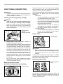
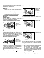
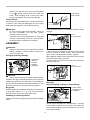
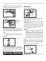
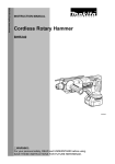
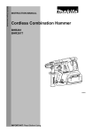
ENGLISH (Original instructions)
INSTRUCTION MANUAL
Cordless Combination Hammer
DHR242
DHR243
012621
IMPORTANT: Read Before Using.
1
ENGLISH (Original instructions)
SPECIFICATIONS
Model
DHR242
DHR243
Concrete
Capacities
24 mm
Steel
13 mm
Wood
27 mm
No load speed (min-1)
0 - 950
Blows per minute
0 - 4,700
Overall length
328 mm
Net weight
3.3 kg
353 mm
3.4 kg
Rated voltage
D.C. 18 V
• Due to our continuing program of research and development, the specifications herein are subject to change without notice.
• Specifications and battery cartridge may differ from country to country.
• Weight, with battery cartridge, according to EPTA-Procedure 01/2003
END004-4
Symbols
Model DHR243
The following show the symbols used for the equipment.
Be sure that you understand their meaning before use.
・ Read instruction manual.
Sound pressure level (LpA) : 89: dB (A)
Sound power level (LWA) : 100 dB (A)
Uncertainty (K) : 3 dB (A)
Cd
Ni-MH
Li-ion
・
Wear ear protection
Only for EU countries
Do not dispose of electric equipment or
battery pack together with household
waste material!
In observance of European Directive
2002/96/EC on waste electric and
electronic equipment, 2006/66/EC on
batteries and accumulators and waste
batteries and accumulators and their
implementation in accordance with
national laws, electric equipment and
battery pack that have reached the end
of their life must be collected separately
and returned to an environmentally
compatible recycling facility.
ENG900-1
Vibration
The vibration total value (tri-axial vector sum) determined
according to EN60745:
Model DHR242
Work mode : hammer drilling into concrete
Vibration emission (ah,HD) : 13.5 m/s2
Uncertainty (K) : 1.5 m/s2
Work mode : chiselling
Vibration emission (ah,CHeq) : 10.5 m/s2
Uncertainty (K) : 1.5 m/s2
ENE043-1
Work mode: drilling into metal
Vibration emission (ah,D) : 3.5 m/s2
Uncertainty (K) : 1.5 m/s2
Intended use
The tool is intended for hammer drilling and drilling in
brick, concrete and stone as well as for chiselling work.
It is also suitable for drilling without impact in wood, metal,
ceramic and plastic.
Model DHR243
Work mode : hammer drilling into concrete
Vibration emission (ah,HD) : 13 m/s2
Uncertainty (K) : 1.5 m/s2
ENG905-1
Noise
The typical A-weighted noise level determined according
to EN60745:
Work mode : chiselling
Vibration emission (ah,CHeq) : 11 m/s2
Uncertainty (K) : 1.5 m/s2
Model DHR242
Sound pressure level (LpA) : 90 dB (A)
Sound power level (LWA) : 101 dB (A)
Uncertainty (K) : 3 dB (A)
Work mode: drilling into metal
Vibration emission (ah,D) : 2.5 m/s2 or less
Uncertainty (K) : 1.5 m/s2
2
ENG901-1
•
•
•
Save all warnings and
instructions for future reference.
The declared vibration emission value has been
measured in accordance with the standard test
method and may be used for comparing one tool
with another.
The declared vibration emission value may also be
used in a preliminary assessment of exposure.
•
The term "power tool" in the warnings refers to your
mains-operated (corded) power tool or battery-operated
(cordless) power tool.
Work area safety
1.
Keep work area clean and well lit. Cluttered or
dark areas invite accidents.
2.
Do not operate power tools in explosive
atmospheres, such as in the presence of
flammable liquids, gases or dust. Power tools
create sparks which may ignite the dust or fumes.
3.
Keep children and bystanders away while
operating a power tool. Distractions can cause
you to lose control.
Electrical safety
4.
Power tool plugs must match the outlet. Never
modify the plug in any way. Do not use any
adapter plugs with earthed (grounded) power
tools. Unmodified plugs and matching outlets will
reduce risk of electric shock.
5.
Avoid body contact with earthed or grounded
surfaces such as pipes, radiators, ranges and
refrigerators. There is an increased risk of
electric shock if your body is earthed or grounded.
6.
Do not expose power tools to rain or wet
conditions. Water entering a power tool will
increase the risk of electric shock.
7.
Do not abuse the cord. Never use the cord for
carrying, pulling or unplugging the power tool.
Keep cord away from heat, oil, sharp edges or
moving parts. Damaged or entangled cords
increase the risk of electric shock.
8.
When operating a power tool outdoors, use an
extension cord suitable for outdoor use. Use of
a cord suitable for outdoor use reduces the risk of
electric shock.
9.
If operating a power tool in a damp location is
unavoidable, use a ground fault circuit
interrupter (GFCI) protected supply. Use of an
GFCI reduces the risk of electric shock.
Personal safety
10. Stay alert, watch what you are doing and use
common sense when operating a power tool.
Do not use a power tool while you are tired or
under the influence of drugs, alcohol or
medication. A moment of inattention while
operating power tools may result in serious
personal injury.
11. Use personal protective equipment. Always
wear eye protection. Protective equipment such
as dust mask, non-skid safety shoes, hard hat, or
hearing protection used for appropriate conditions
WARNING:
The vibration emission during actual use of the
power tool can differ from the declared emission
value depending on the ways in which the tool is
used.
Be sure to identify safety measures to protect the
operator that are based on an estimation of
exposure in the actual conditions of use (taking
account of all parts of the operating cycle such as
the times when the tool is switched off and when it
is running idle in addition to the trigger time).
ENH101-17
For European countries only
EC Declaration of Conformity
Makita declares that the following Machine(s):
Designation of Machine:
Cordless Combination Hammer
Model No./ Type: DHR242, DHR243
Conforms to the following European Directives:
2006/42/EC
They are manufactured in accordance with the following
standard or standardized documents:
EN60745
The technical file in accordance with 2006/42/EC is
available from:
Makita, Jan-Baptist Vinkstraat 2, 3070, Belgium
31.12.2013
000331
Yasushi Fukaya
Director
Makita, Jan-Baptist Vinkstraat 2, 3070, Belgium
GEA006-2
General Power Tool Safety
Warnings
WARNING Read all safety warnings and all
instructions. Failure to follow the warnings and
instructions may result in electric shock, fire and/or
serious injury.
3
and the work to be performed. Use of the power
tool for operations different from those intended
could result in a hazardous situation.
Battery tool use and care
24. Recharge only with the charger specified by
the manufacturer. A charger that is suitable for
one type of battery pack may create a risk of fire
when used with another battery pack.
25. Use power tools only with specifically
designated battery packs. Use of any other
battery packs may create a risk of injury and fire.
26. When battery pack is not in use, keep it away
from other metal objects, like paper clips,
coins, keys, nails, screws or other small metal
objects, that can make a connection from one
terminal to another. Shorting the battery
terminals together may cause burns or a fire.
27. Under abusive conditions, liquid may be
ejected from the battery; avoid contact. If
contact accidentally occurs, flush with water.
If liquid contacts eyes, additionally seek
medical help. Liquid ejected from the battery may
cause irritation or burns.
Service
28. Have your power tool serviced by a qualified
repair person using only identical replacement
parts. This will ensure that the safety of the power
tool is maintained.
29. Follow instruction for lubricating and
changing accessories.
30. Keep handles dry, clean and free from oil and
grease.
will reduce personal injuries.
Prevent unintentional starting. Ensure the
switch is in the off-position before connecting
to power source and/or battery pack, picking
up or carrying the tool. Carrying power tools with
your finger on the switch or energising power tools
that have the switch on invites accidents.
13. Remove any adjusting key or wrench before
turning the power tool on. A wrench or a key left
attached to a rotating part of the power tool may
result in personal injury.
14. Do not overreach. Keep proper footing and
balance at all times. This enables better control
of the power tool in unexpected situations.
15. Dress properly. Do not wear loose clothing or
jewellery. Keep your hair, clothing, and gloves
away from moving parts. Loose clothes,
jewellery or long hair can be caught in moving
parts.
16. If devices are provided for the connection of
dust extraction and collection facilities, ensure
these are connected and properly used. Use of
dust collection can reduce dust-related hazards.
Power tool use and care
17. Do not force the power tool. Use the correct
power tool for your application. The correct
power tool will do the job better and safer at the
rate for which it was designed.
18. Do not use the power tool if the switch does
not turn it on and off. Any power tool that cannot
be controlled with the switch is dangerous and
must be repaired.
19. Disconnect the plug from the power source
and/or the battery pack from the power tool
before making any adjustments, changing
accessories, or storing power tools. Such
preventive safety measures reduce the risk of
starting the power tool accidentally.
20. Store idle power tools out of the reach of
children and do not allow persons unfamiliar
with the power tool or these instructions to
operate the power tool. Power tools are
dangerous in the hands of untrained users.
21. Maintain power tools. Check for misalignment
or binding of moving parts, breakage of parts
and any other condition that may affect the
power tool’s operation. If damaged, have the
power tool repaired before use. Many accidents
are caused by poorly maintained power tools.
22. Keep cutting tools sharp and clean. Properly
maintained cutting tools with sharp cutting edges
are less likely to bind and are easier to control.
23. Use the power tool, accessories and tool bits
etc. in accordance with these instructions,
taking into account the working conditions
12.
GEB046-2
CORDLESS ROTARY HAMMER
SAFETY WARNINGS
1.
2.
3.
4.
5.
4
Wear ear protectors. Exposure to noise can
cause hearing loss.
Use auxiliary handle(s), if supplied with the
tool. Loss of control can cause personal injury.
Hold power tool by insulated gripping surfaces,
when performing an operation where the
cutting accessory may contact hidden wiring.
Cutting accessory contacting a "live" wire may
make exposed metal parts of the power tool "live"
and could give the operator an electric shock.
Wear a hard hat (safety helmet), safety glasses
and/or face shield. Ordinary eye or sun
glasses are NOT safety glasses. It is also
highly recommended that you wear a dust
mask and thickly padded gloves.
Be sure the bit is secured in place before
operation.
6.
7.
8.
9.
10.
11.
12.
13.
14.
Under normal operation, the tool is designed
to produce vibration. The screws can come
loose easily, causing a breakdown or accident.
Check tightness of screws carefully before
operation.
In cold weather or when the tool has not been
used for a long time, let the tool warm up for a
while by operating it under no load. This will
loosen up the lubrication. Without proper
warm-up, hammering operation is difficult.
Always be sure you have a firm footing.
Be sure no one is below when using the tool in
high locations.
Hold the tool firmly with both hands.
Keep hands away from moving parts.
Do not leave the tool running. Operate the tool
only when hand-held.
Do not point the tool at any one in the area
when operating. The bit could fly out and
injure someone seriously.
Do not touch the bit or parts close to the bit
immediately after operation; they may be
extremely hot and could burn your skin.
Some material contains chemicals which may
be toxic. Take caution to prevent dust
inhalation and skin contact. Follow material
supplier safety data.
5.
6.
7.
8.
9.
SAVE THESE INSTRUCTIONS.
Tips for maintaining maximum battery life
1.
SAVE THESE INSTRUCTIONS.
2.
WARNING:
DO NOT let comfort or familiarity with product
(gained from repeated use) replace strict adherence
to safety rules for the subject product. MISUSE or
failure to follow the safety rules stated in this
instruction manual may cause serious personal
injury.
3.
4.
ENC007-7
IMPORTANT SAFETY
INSTRUCTIONS
FOR BATTERY CARTRIDGE
1.
2.
3.
4.
attention right away. It may result in loss of
your eyesight.
Do not short the battery cartridge:
(1) Do not touch the terminals with any
conductive material.
(2) Avoid storing battery cartridge in a
container with other metal objects such as
nails, coins, etc.
(3) Do not expose battery cartridge to water
or rain.
A battery short can cause a large current flow,
overheating, possible burns and even a
breakdown.
Do not store the tool and battery cartridge in
locations where the temperature may reach or
exceed 50 ゚ C (122 ゚ F).
Do not incinerate the battery cartridge even if it
is severely damaged or is completely worn out.
The battery cartridge can explode in a fire.
Be careful not to drop or strike battery.
Do not use a damaged battery.
Before using battery cartridge, read all
instructions and cautionary markings on (1)
battery charger, (2) battery, and (3) product
using battery.
Do not disassemble battery cartridge.
If operating time has become excessively
shorter, stop operating immediately. It may
result in a risk of overheating, possible burns
and even an explosion.
If electrolyte gets into your eyes, rinse them
out with clear water and seek medical
5
Charge
the
battery
cartridge
before
completely discharged.
Always stop tool operation and charge the
battery cartridge when you notice less tool
power.
Never recharge a fully charged battery
cartridge.
Overcharging shortens the battery service life.
Charge the battery cartridge with room
temperature at 10 ゚ C - 40 ゚ C (50 ゚ F - 104 ゚ F).
Let a hot battery cartridge cool down before
charging it.
Charge the battery cartridge once in every six
months if you do not use it for a long period of
time.
Lithium-ion batteries with a star marking are equipped
with a protection system. This system automatically cuts
off power to the tool to extend battery life.
The tool will automatically stop during operation if the tool
and/or battery are placed under one of the following
conditions:
•
Overloaded:
The tool is operated in a manner that causes
it to draw an abnormally high current.
In this situation, release the trigger switch on
the tool and stop the application that caused
the tool to become overloaded. Then pull the
trigger switch again to restart.
If the tool does not start, the battery is
overheated. In this situation, let the battery
cool before pulling the trigger switch again.
•
Low battery voltage:
The remaining battery capacity is too low and
the tool will not operate. In this situation,
remove and recharge the battery.
FUNCTIONAL DESCRIPTION
•
CAUTION:
Always be sure that the tool is switched off and the
battery cartridge is removed before adjusting or
checking function on the tool.
Installing or removing battery cartridge
•
CAUTION:
Hold the tool and the battery cartridge firmly
when installing or removing battery cartridge.
Failure to hold the tool and the battery cartridge
firmly may cause them to slip off your hands and
result in damage to the tool and battery cartridge
and a personal injury.
1. Red indicator
2. Button
3. Battery cartridge
1
2
Switch action
1. Switch trigger
3
012622
•
•
•
•
Always switch off the tool before installing or
removing of the battery cartridge.
To remove the battery cartridge, slide it from the tool
while sliding the button on the front of the cartridge.
To install the battery cartridge, align the tongue on
the battery cartridge with the groove in the housing
and slip it into place. Always insert it all the way
until it locks in place with a little click. If you can see
the red indicator on the upper side of the button, it is
not locked completely. Install it fully until the red
indicator cannot be seen. If not, it may accidentally
fall out of the tool, causing injury to you or someone
around you.
Do not use force when installing the battery
cartridge. If the cartridge does not slide in easily, it
is not being inserted correctly.
1
012627
CAUTION:
Before inserting the battery cartridge into the tool,
always check to see that the switch trigger actuates
properly and returns to the "OFF" position when
released.
To start the tool, simply pull the switch trigger. Tool speed
is increased by increasing pressure on the switch trigger.
Release the switch trigger to stop.
•
Reversing switch action
1
1. Reversing switch
lever
1
Battery protection system
(Lithium-ion battery with star marking)
A
B
1. Star marking
012628
This tool has a reversing switch to change the direction of
rotation. Depress the reversing switch lever from the A
side for clockwise rotation or from the B side for
counterclockwise rotation.
012128
6
When the reversing switch lever is in the neutral position,
the switch trigger cannot be pulled.
•
•
•
Selecting the action mode
Rotation with hammering
CAUTION:
Always check the direction of rotation before
operation.
Use the reversing switch only after the tool comes
to a complete stop. Changing the direction of
rotation before the tool stops may damage the tool.
When not operating the tool, always set the
reversing switch lever to the neutral position.
1. Rotation with
hammering
2. Lock button
3. Action mode
changing knob
1
Changing the quick change chuck for
SDS-plus
1. Rotation only
1. Quick change
chuck for
SDS-plus
2. Change cover
line
3. Change cover
2
1
012631
3
For drilling in wood, metal or plastic materials, depress
the lock button and rotate the action mode changing
knob to the
symbol. Use a twist drill bit or wood bit.
Hammering only
012690
CAUTION:
Before removing the quick change chuck for
SDS-plus, always remove the bit.
Grasp the change cover of the quick change chuck for
SDS-plus and turn in the direction of the arrow until the
change cover line moves from the
symbol to the
symbol. Pull forcefully in the direction of the arrow.
Attaching the quick change drill chuck
•
2
1. Hammering only
1. Spindle
2. Quick change
drill chuck
3. Change cover
4. Change cover
line
1
3
3
For drilling in concrete, masonry, etc., depress the lock
button and rotate the action mode changing knob to the
symbol. Use a tungsten-carbide tipped bit.
Rotation only
For model DHR243
The quick change chuck for SDS-plus can be easily
exchanged for the quick change drill chuck.
Removing the quick change chuck for SDS-plus
1
2
012629
1
012630
For chipping, scaling or demolition operations, depress
the lock button and rotate the action mode changing
knob to the
symbol. Use a bull point, cold chisel,
scaling chisel, etc.
4
012689
Check the line of the quick change drill chuck shows the
symbol. Grasp the change cover of the quick change
drill chuck and set the line to the
symbol.
Place the quick change drill chuck on the spindle of the
tool.
Grasp the change cover of the quick change drill chuck
and turn the change cover line to the
symbol until a
click can clearly be heard.
•
•
•
7
CAUTION:
Do not rotate the action mode changing knob when
the tool is running. The tool will be damaged.
To avoid rapid wear on the mode change
mechanism, be sure that the action mode changing
knob is always positively located in one of the three
action mode positions.
When changing from the
symbol mode to the
symbol mode, the action mode changing knob
may no longer move in the
symbol position. At
this time, turn the tool on or turn the chuck by hand
in the
symbol position and then rotate the
action mode changing knob. Forcing the action
mode changing knob may cause tool damage.
1. Bit shank
2. Bit grease
1
Torque limiter
The torque limiter will actuate when a certain torque level
is reached. The motor will disengage from the output
shaft. When this happens, the bit will stop turning.
•
•
2
001296
CAUTION:
As soon as the torque limiter actuates, switch off
the tool immediately. This will help prevent
premature wear of the tool.
Hole saws cannot be used with this tool. They tend
to pinch or catch easily in the hole. This will cause
the torque limiter to actuate too frequently.
Insert the bit into the tool. Turn the bit and push it in until it
engages.
ASSEMBLY
•
1
CAUTION:
Always be sure that the tool is switched off and the
battery cartridge is removed before carrying out
any work on the tool.
012624
If the bit cannot be pushed in, remove the bit. Pull the
chuck cover down a couple of times. Then insert the bit
again. Turn the bit and push it in until it engages.
After installing, always make sure that the bit is securely
held in place by trying to pull it out.
To remove the bit, pull the chuck cover down all the way
and pull the bit out.
Side grip (auxiliary handle)
1
3
2
4
1. Bit
2. Chuck cover
2
1. Protrusion
2. Groove
3. Loosen
4. Tighten
5. Side grip
1. Bit
2. Chuck cover
2
5
1
012623
CAUTION:
Always use the side grip to ensure operating safety.
Install the side grip so that the protrusion on the grip fit in
between the grooves in the tool barrel. Then tighten the
grip by turning clockwise at the desired position. It may
be swung 360° so as to be secured at any position.
•
012625
Bit angle
(when chipping, scaling or demolishing)
Bit grease
1. Action mode
changing knob
2. O symbol
Coat the bit shank head beforehand with a small amount
of bit grease (about 0.5 -1 g). This chuck lubrication
assures smooth action and longer service life.
Installing or removing the bit
Clean the bit shank and apply bit grease before installing
the bit.
2
1
012632
The bit can be secured at the desired angle. To change
the bit angle, depress the lock button and rotate the
action mode changing knob to the O symbol. Turn the bit
to the desired angle.
8
Depress the lock button and rotate the action mode
changing knob to the symbol. Then make sure that the
bit is securely held in place by turning it slightly.
OPERATION
Hammer drilling operation
012633
012634
Depth gauge
Set the action mode changing knob to the
symbol.
Position the bit at the desired location for the hole, then
pull the switch trigger.
Do not force the tool. Light pressure gives best results.
Keep the tool in position and prevent it from slipping
away from the hole.
Do not apply more pressure when the hole becomes
clogged with chips or particles. Instead, run the tool at an
idle, then remove the bit partially from the hole. By
repeating this several times, the hole will be cleaned out
and normal drilling may be resumed.
1. Hole
2. Depth gauge
3. Loosen
4. Tighten
1
3
2
4
012626
The depth gauge is convenient for drilling holes of
uniform depth. Loosen the side grip and insert the depth
gauge into the hole in the side grip. Adjust the depth
gauge to the desired depth and tighten the side grip.
•
NOTE:
•
The depth gauge cannot be used at the position
where the depth gauge strikes against the gear
housing.
Dust cup
1. Dust cup
CAUTION:
There is a tremendous and sudden twisting force
exerted on the tool/bit at the time of hole
break-through, when the hole becomes clogged
with chips and particles, or when striking reinforcing
rods embedded in the concrete. Always use the
side grip (auxiliary handle) and firmly hold the tool
by both side grip and switch handle during
operations. Failure to do so may result in the loss of
control of the tool and potentially severe injury.
NOTE:
Eccentricity in the bit rotation may occur while operating
the tool with no load. The tool automatically centers itself
during operation. This does not affect the drilling
precision.
1
Blow-out bulb (optional accessory)
1. Blow-out bulb
012636
Use the dust cup to prevent dust from falling over the tool
and on yourself when performing overhead drilling
operations. Attach the dust cup to the bit as shown in the
figure. The size of bits which the dust cup can be
attached to is as follows.
Dust cup 5
Dust cup 9
1
Bit diameter
6 mm - 14.5 mm
12 mm - 16 mm
002449
After drilling the hole, use the blow-out bulb to clean the
dust out of the hole.
006382
9
Chipping/Scaling/Demolition
1. Quick change
chuck for
SDS-plus
2. Change cover
line
3. Change cover
2
1
3
012690
012686
Set the action mode changing knob to the
symbol.
Hold the tool firmly with both hands. Turn the tool on and
apply slight pressure on the tool so that the tool will not
bounce around, uncontrolled. Pressing very hard on the
tool will not increase the efficiency.
2
Drilling in wood or metal
3
1. Chuck adapter
2. Keyless drill
chuck
1
1. Spindle
2. Quick change
drill chuck
3. Change cover
4. Change cover
line
1
4
012689
Use the quick change drill chuck as standard equipment.
When installing it, refer to "changing the quick change
chuck for SDS-plus " described on the previous page.
2
1. Quick change
drill chuck
2. Sleeve
3. Ring
1
012684
1. Sleeve
2. Ring
1
2
3
012720
Hold the ring and turn the sleeve counterclockwise to
open the chuck jaws. Place the bit in the chuck as far as it
will go. Hold the ring firmly and turn the sleeve clockwise
to tighten the chuck. To remove the bit, hold the ring and
turn the sleeve counterclockwise.
Set the action mode changing knob to the
symbol.
You can drill up to 13 mm diameter in metal and up to 32
mm diameter in wood.
2
012685
Use the optional drill chuck assembly. When installing it,
refer to "Installing or removing the bit" described on the
previous page.
Set the action mode changing knob so that the pointer
points to the symbol.
For model DHR243
•
•
CAUTION:
Never use "rotation with hammering" when the drill
chuck assembly is installed on the tool. The drill
chuck assembly may be damaged. Also, the drill
chuck will come off when reversing the tool.
•
•
10
CAUTION:
Never use "rotation with hammering" when the
quick change drill chuck is installed on the tool. The
quick change drill chuck may be damaged.
Also, the drill chuck will come off when reversing
the tool.
Pressing excessively on the tool will not speed up
the drilling. In fact, this excessive pressure will only
serve to damage the tip of your bit, decrease the
tool performance and shorten the service life of the
tool.
There is a tremendous twisting force exerted on the
tool/bit at the time of hole breakthrough. Hold the
•
•
tool firmly and exert care when the bit begins to
break through the workpiece.
A stuck bit can be removed simply by setting the
reversing switch to reverse rotation in order to back
out. However, the tool may back out abruptly if you
do not hold it firmly.
Always secure small workpieces in a vise or similar
hold-down device.
NOTE:
•
Some items in the list may be included in the tool
package as standard accessories. They may differ
from country to country.
MAINTENANCE
CAUTION:
Always be sure that the tool is switched off and the
battery cartridge is removed before attempting to
perform inspection or maintenance.
•
Never use gasoline, benzine, thinner, alcohol or the
like. Discoloration, deformation or cracks may result.
To maintain product SAFETY and RELIABILITY, repairs,
carbon brush inspection and replacement, any other
maintenance or adjustment should be performed by
Makita Authorized Service Centers, always using Makita
replacement parts.
•
OPTIONAL ACCESSORIES
CAUTION:
These
accessories
or
attachments
are
recommended for use with your Makita tool
specified in this manual. The use of any other
accessories or attachments might present a risk of
injury to persons. Only use accessory or
attachment for its stated purpose.
If you need any assistance for more details regarding
these accessories, ask your local Makita Service Center.
•
SDS-Plus Carbide-tipped bits
•
Bull point
•
Cold chisel
•
Scaling chisel
•
Grooving chisel
•
Drill chuck assembly
•
Drill chuck S13
•
Chuck adapter
•
Chuck key S13
•
Bit grease
•
Side grip
•
Depth gauge
•
Blow-out bulb
•
Dust cup
•
Dust extractor attachment
•
Safety goggles
•
Plastic carrying case
•
Keyless drill chuck
•
Various type of Makita genuine batteries and
chargers
•
11
Makita Jan-Baptist Vinkstraat 2, 3070, Belgium
Makita Corporation Anjo, Aichi, Japan
885236A226
www.makita.com
12