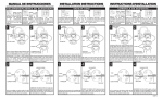
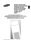
1
Arrive EyePoint AEP-3030
TM
USB 3.0 HD CAMERA
Please note the serial number of your purchased product for future reference:
AEP-3030-UPTZ
Model No.: _________________
AEP-3030-804-001
Serial No.:___________________________________________
USER MANUAL
We reserve the right to introduce changes after the printing of this document. Please refer to our website www.arrivesys.com
for updated documentation and information.
© 2014 Arrive Systems, Inc. All Rights Reserved.
2
CONTENTS
1. INTRODUCTION.................................................................................................................................................... 9
2. FEATURES AND SPECIFICATIONS....................................................................................................................... 9
3. INSTALLING THE DEVICE...................................................................................................................................12
4. USING THE DEVICE.............................................................................................................................................15
5. CONNECTING THE CAMERA.............................................................................................................................21
6. TROUBLESHOOTING..........................................................................................................................................25
© 2014 Arrive Systems, Inc. All Rights Reserved.
3
IMPORTANT SAFETY INSTRUCTIONS
CAUTION
RISK OF ELECTRIC SHOCK
DO NOT OPEN
CAUTION: TO REDUCE THE RISK OF
ELECTRIC SHOCK, DO NOT REMOVE COVER
(OR BACK). NO USER-SERVICEABLE PARTS
INSIDE. REFER SERVICING TO QUALIFIED
PERSONNEL
12.Lightning - For added protection for this product during a
lightning storm, or when it is left unattended and unused for
long periods of time, unplug it from the ethernet and/or from
the power socket. This will prevent damage to the product
due to lightning.
13. Object and liquid entry - Never push objects of any kind into
this product through openings as they may touch dangerous
voltage points or short-out parts that could result in a fire or
electric shock. Never spill liquid of any kind on the product.
14.Servicing - Do not attempt to service this product yourself as
opening or removing covers may expose you to dangerous
voltage or other hazards. Refer all servicing to qualified
service personnel.
15.Damage Requiring Service - Unplug this product from the
ethernet and/or power socket and refer servicing to qualified
service personnel under the following conditions :
a) When the connecting cable is damaged,
Explanation of Graphical Symbols
This graphic symbol is intended to alert you to
the presence of uninsulated “dangerous voltage”
within the product’s enclosure that may be of
sufficient magnitude to constitute a risk of electric
shock to persons
This graphic symbol is intended to alert you the
presence of important operating and maintenance
accompanying the appliance.
1. Read Instructions - All the safety and operating instructions
should be read before you operate the product.
2. Retain Instruction-The safety and operating instructions
should retained for future reference.
3. Heed Warnings - All warnings on the product and in the
operating instructions should be adhered to.
4. Follow Instructions - All operating and use instructions should
be followed.
5. Cleaning - Unplug this product before cleaning. Do not use
liquid cleaners or aerosol cleaners.
b) If liquid has been spilled, or objects have fallen into the
products,
c) If the product has been exposed to the rain and water,
d) If the product does not operate normally by following the
operating instructions. Adjust only those controls that
are covered by the operating instructions as an improper
adjustment of the controls may result in damage and will
often require extensive work by a qualified technician to
restore the product to its normal operation,
e) If the product has been dropped or damaged in any way,
and
f) When the product exhibits a distinct change in
performances- this indicates a need of service.
16.Replacement Parts - When replacement parts are required,
be sure the service technician has used replacement parts
specified by the manufacturer or have the same characteristics
as the original part. Unauthorized substitutions may result in
fire, electric shock, or other hazards.
17.Safety Check - Upon completion of any service or repair to this
product, ask the service technician to perform safety checks to
determine that the product is in proper operating condition.
18.Heat - The product should be situated away from heat sources
such radiators, heat registers, stoves, or other product
(including amplifiers) that produce heat.
6. Attachments - Do not use attachments not recommended by
the product manufacturer as they can cause hazards.
7. Water and Moisture - Do not use this product near water- near
a bath tub, wash bowl, kitchen sink, or laundry tub; in a wet
basement; or near a swimming pool; and the like.
8. Accessories - Do not place this product on an unstable cart,
stand, tripod, bracket or table. The product may fall, causing
serious injury to a child or adult, and serious damage to
the product. Use only with a bracket, recommended by the
manufacturer or sold with the product. Any mounting of
the product should follow the manufacturer’s instructions,
and should use a mounting accessory recommended by
manufacturer.
9. A product and cart combination should be moved with care.
Quick stops, excessive force, and uneven surfaces may cause
the product and cart combination to overturn.
10.Power Sources - This product should be operated only from
the type of power source indicated on the mark.
11. Cable Protection - All connected cables should be routed so
that they are not likely to be walked on or pinched by items
placed upon or against them, paying particular attention to
cords at plugs, convenience receptacles, and the point where
they exit from the product.
© 2014 Arrive Systems, Inc. All Rights Reserved.
4
COMPLIANCE INFORMATION
(DECLARATION OF CONFORMITY PROCEDURE)
Responsible Party: Arrive Systems, Inc.
Address: 6737 Katella Ave., Cypress CA 90630 USA
Telephone: +1-844-427-7483 (Toll Free)
Hour of operation: 9:00 - 17:00
Type of Equipment: USB 3.0 HD Cameras
Model Name: AEP-3030-UPTZ
This device complies with Part 15 of FCC Rules. Operation is
subject to the following conditions:
This Device complies with the requirements listed in FCC
regularizations, Part 15 for Class “A” Digital devices. If you
are using cardiac pacemaker, please note that this device can
radiate radio frequency energy in the area near the product
1) this device may not cause harmful interference, and
2) this device must accept any interference received the
including the interference that may cause undesired
operation.
See user manual instructions if interference to radio
reception is suspected.
FCC INFORMATION (for US customers)
1. IMPORTANT NOTICE: DO NOT MODIFY THIS UNIT!
This product, when installed as indicated in the
instructions contained in the manual, meets FCC
requirements. Modifications not expressly approved by
ARRIVE may void your authority granted by FCC to use the
product.
2. IMPORTANT: When connecting this product to
accessories and/or another product, use only high quality
shielded cables. Cable/s supplied with this product MUST
be used. Follow all installation instructions. Failure to
follow instructions could void your FCC authorizations to
use this product in the USA.
3. NOTE: This has been tested and found to comply with the
requirements listed in FCC regulations, Part 15 for Class
“A” digital devices. Compliance with these requirements
provides a reasonable level assurance that your use of
this product in a residential environment will not result in
harmful interference with other electronic devices. This
equipment generates/uses radio frequencies and, if not
installed and used according to the instructions found in
the user manual, may cause interference harmful to the
operation of other electronic devices.
product is found to be the source of interference ,which
can be determined by turning the unit “OFF” and “ON”,
please try to eliminate the problem by using one of the
following measures;
Relocate either this product or the device that is being
affected by the interference.
Utilize power outlets that are on different branch (circuit
breaker of fuse) circuits or install AC line filter/s.
In the case of radio or TV interference, relocate/reorient
the antenna. If the antenna lead-in is 300 ohm ribbon lead,
change the lead-in to co-axial type cable.
If these corrective measures do not produce satisfactory
results, please contact the local retailer authorized to
distribute this type of product. If you cannot locate the
appropriate retailer, please contact Arrive Systems, Inc.
Address: 6737 Katella Ave., Cypress CA 90630 USA
The above statements apply ONLY to those products
distributed by Arrive Systems, Inc.
Compliance with FCC regulations does not guarantee that
the interference will not occur in all installations, If this
FOR CANADIAN CUSTOMERS
This Class A digital apparatus complies with Canadian ICES-003.
CE Declaration of Conformity (For EU Customers)
We, Arrive Systems, Inc., declare under our sole responsibility that the Arrive component to which this declaration relates, is in
conformity with General Emissions Standard EN50081-1 and with Generic Immunity Standard EN50082-1 1992.
© 2014 Arrive Systems, Inc. All Rights Reserved.
5
CAUTION: READ THIS BEFORE OPERATING YOUR UNIT
1. To assure the finest performance, please read this manual
carefully. Keep it in a safe place for future reference.
2. Install this unit in a well-ventilated, cool, dry, clean place away
from direct sunlight, heat sources, vibration, dust, moisture,
and/or cold.
WARNING
TO REDUCE THE RISK OF FIRE OR ELECTRIC SHOCK, DO NOT
EXPOSE THIS UNIT TO RAIN OR MOISTURE.
3. Locate this unit away from other electrical appliances, motors,
or transformers to avoid humming sounds.
4. Do not expose this unit to sudden temperature changes from
cold or hot, and do not locate this unit on an environment
with high humidity (i.e. a room with a humidifier) to prevent
condensation inside this unit, and/or personal injury.
5. Avoid installing this unit where foreign object may fall onto
this unit and/or this unit may be exposed to liquid dripping or
splashing. On the top of this unit, do not place :
• Other components, as they may cause damage and/or
discoloration on the surface of this unit.
• Burning objects (i.e. candles), as they may fall and liquid
may cause electrical shock to the user and/or damage
to this unit.
• Containers with liquid in them, as they may fall and liquid
may cause electrical shock to the user and/or damage
to this unit.
6. Do not cover this unit with a newspaper, tablecloth, curtain,
etc. in order not to obstruct heat radiation. If the temperature
inside this unit rises, it may cause fire, damage to this unit,
and/or personal injury.
7. Do not install this unit near mobile phones and/or televisions
sets to prevent operation failure caused by electromagnetic
waves and/or magnetism.
8. Install this unit in a stable place to prevent a fall and damage
to this unit.
9. Keep your hands dry when connecting or disconnecting the
cable to prevent an electric shock.
10.Connect USB ports on the device directly to PC. Connecting
them through a USB hub may cause problems in operations.
11.Do not use force in the cable. Doing so may cause a fire,
electrical shock, damage to this unit, short circuit and/or
disconnecting.
12.When not planning to use this unit for long periods of time,
disconnect the cable from the ethernet and/or power sockets
to prevent fire.
13.When disconnecting any cable, grasp the plug- do not pull the
cable.
14.Do not clean this unit with chemical solvents; this might
damage the finish. Use a clean or dry cloth.
WARNING
TO PREVENT ELECTRIC SHOCK, ENSURE THAT YOU ARE
USING MATCHING POWER PLUGS TO THE POWER SOCKET
AND FULLY INSERT.
Information for users on collection and disposal of old
equipment
This symbol on the products,
packaging, and/or accompanying
documents means that used
electrical and electronic products
should not be mixed with general
household waste.
For proper treatment, recovery and
recycling of old products, please
take them to applicable collection
points, in accordance with your
national legislation and Directives
2002/96/EC.
By disposing of these products correctly, you will help to
save valuable resources and prevent any potential negative
effects on human health and the environment which could
otherwise arise from inappropriate waste handling.
For more information about collection and recycling of old
products, please contact your local municipality, your waste
disposal service or the point of sale where you purchased
the items.
[For business users in the European Union]
If you wish to discard electrical and electronic equipment,
please contact your dealer or supplier for further
information.
[Information on Disposal in other Countries outside the
European Union]
This symbol is only valid in European Union, If you wish to
discard these items, please contact your local authorities or
dealer and ask for the correct methods of disposal.
15.Do not attempt to modify or fix this unit. Contact qualified
ARRIVE service personnel when any service is needed.
16.Condensation will form when any surrounding temperature
changes suddenly. Disconnect the cables, then leave this unit
alone.
17.When using this unit for a long time, this unit may become
warm. Disconnect the cables, then leave this unit alone for
cooling.
18.To prevent damage by lightning, keep the cables disconnected
during a lightning storm.
© 2014 Arrive Systems, Inc. All Rights Reserved.
6
COPYRIGHT NOTICE
No part of this document may be reproduced or transmitted in any form, or by any means without the prior written permission of
Arrive® (ARRIVE). ARRIVE reserves the rights to modify its documentation and product features, including their characteristics,
specifications, accessories and any other information stated herein without notice. The official printout of any information shall prevail
should there be any discrepancy between the information contained herein and the information contained in that printout. This product
and related documentation are proprietary to ARRIVE.
This document does not provide you with any legal rights to any intellectual property in any ARRIVE product. You may copy and use this
document for your internal, reference purposes.
■■ Disclaimer
THE SPECIFICATIONS, INFORMATION, DESIGNS, STATEMENTS, AND RECOMMENDATIONS (COLLECTIVELY, “INFORMATION”)
REGARDING THE PRODUCTS IN THIS MANUAL ARE SUBJECT TO CHANGE WITHOUT NOTICE,AND ALL IMAGES ARE FOR REFERENCE
USE ONLY.FINISHED GOODS, PACKAGING,AND PRODUCTS WILL BE PROVIDED WITH USER DESIGNS AND GRAPHIC ELEMENTS
INCLUDING PACKAGING DESIGN ELEMENTS THAT MAY VARY FROM THE IMAGES SHOWN IN THIS DOCUMENT.E&OE. ALL STATEMENTS,
INFORMATION, AND RECOMMENDATIONS IN THIS MANUAL ARE BELIEVED TO BE ACCURATE BUT ARE PRESENTED WITHOUT
WARRANTY OF ANY KIND, EXPRESS OR IMPLIED. USERS MUST TAKE FULL RESPONSIBILITY FOR THEIR APPLICATION OF ANY
PRODUCTS. ARRIVE DISCLAIMS ALL WARRANTIES, INCLUDING, WITHOUT LIMITATION, THE WARRANTY OF MERCHANTABILITY, FITNESS
FOR A PARTICULAR PURPOSE AND NON-INFRINGEMENT OR ARISING FROM A COURSE OF DEALING, USAGE, OR TRADE PRACTICE. IN
NO EVENT SHALL ARRIVE OR ITS INFORMATION SOURCES AND SUPPLIERS BE LIABLE FOR ANY INDIRECT, SPECIAL, CONSEQUENTIAL,
OR INCIDENTAL DAMAGES, INCLUDING, WITHOUT LIMITATION, LOST PROFITS, LOSS OR DAMAGE TO DATA ARISING OUT OF THE USE
OR INABILITY TO USE THIS MANUAL, EVEN IF ARRIVE OR ITS SUPPLIERS HAVE BEEN ADVISED OF THE POSSIBILITY OF SUCH DAMAGES.
ALL TRADEMARKS AND INFORMATION ARE OWNED BY THE RESPECTIVE OWNERS OF THE TRADEMARKS AND INFORMATION,
WHETHER ACKNOWLEDGED OR NOT IN THIS MANUAL. ARRIVE DOES NOT CLAIM ANY OWNERSHIP OF ANY TRADEMARK OR
TRADENAME MENTIONED IN THE INFORMATION EXCEPT FOR THE ARRIVE TRADENAMES – ARRIVE, ARRIVE FACEPOINT, ARRIVE
INFOPOINT, ARRIVE ROOMPOINT, ARRIVE CONTROLPOINT, ARRIVE EYEPOINT, ARRIVE TOUCHPOINT, ARRIVE VIEWPOINT, ARRIVE
VOICEPOINT, ARRIVE SOUNDPOINT AND ARRIVE EDGELESS MEDIA SERVER.
MICROSOFT, MICROSOFT WINDOWS, MICROSOFT WINDOWS SERVER, MICROSOFT LYNC, MICROSOFT EXCHANGE, MICROSOFT ACTIVE
DIRECTORY AND MICROSOFT IIS ARE THE TRADEMARKS OF MICROSOFT CORPORATION.
■■ Fictional user of “Visionergy” and/or “Verity” name in examples
Arrive Systems Inc. uses a variety of fictional companies in the documentation and training material for its products. ARRIVE
documentation and learning materials often contain fictional scenarios and descriptions of how our products can be deployed and
used in these scenarios. Some examples depicted herein such as the corporate name “Visionergy” and/or “Verity”, just like “Contoso”
is generally used by Microsoft®. These names are provided for illustration only and are fictitious. No real association or connection is
intended or should be inferred. Any Internet Protocol (IP) addresses and phone numbers used in this document are not intended to be
actual addresses and phone numbers. Any examples, command display output, network topology diagrams, and other figures included
in the document are shown for illustrative purposes only. Any use of actual IP addresses or phone numbers in illustrative content is
unintentional and coincidental.
ARRIVE disclaims ownership of the brand or use or association of the name “Visionergy” and/ or “Verity” as a real business or business
entity and does not recommend the use of this name by others for a similar purpose of creating examples to avoid confusion. The
domain visionergy.com is set to reflect to arrivesys.com.
© 2014 Arrive Systems, Inc. All Rights Reserved.
7
ABOUT THIS MANUAL
In this manual, brand names may be described as the brands or abbreviated as follows.
• Arrive EyePoint™-3030-UPTZ: this unit, device
■■ About Trademarks
• All other trademarks are owned by their respective owners whether acknowledged or not in
this manual.
• Specifications of this unit and contents of this document are subject to change without notice.
• ARRIVE does not accept any liability for any loss or damage resulting from any use of this unit. the warranty covers this unit
only.
© 2014 Arrive Systems, Inc. All Rights Reserved.
8
1. INTRODUCTION
■■ Document scope
The document provides the usage guidelines for Arrive EyePoint™ 3030 UPTZ family of USB 3.0 HD
cameras. It guides you through the features, technical specifications, and steps in deploying and
configuring the camera. It also provides best practices information for unit installation and use.
■■ Product overview
Arrive EyePoint™ 3030 UPTZ comes from the family of USB 3.0 super-speed HD cameras from Arrive®.
It offers unparalleled clarity and resolution for a host of applications, irrespective of room sizes and
light conditions. They are ideal solutions for video conferencing, distance learning, training, meeting,
courtroom and any other application that involves high- quality color video cameras with the flexibility
of remote operations. The small form factor coupled with easy installation requirements make them
an ace solution for video capture needs.
2. FEATURES AND SPECIFICATIONS
■■ Port specifications
Figure 1: EyePoint-3030-UPTZ
© 2014 Arrive Systems, Inc. All Rights Reserved.
9
Figure 2: Rear Panel
Field
Description
USB 3.0 interface
A super- speed transfer interface
IR Receiver
Sensor to receive IR remote controller signal
VISCA IN/ RS232
VISCA OUT//RS485 Control
Interface
Accomodates daisy chain connection of multiple cameras. When
multiple cameras are connected to PC via RS-232C (VISCA IN),
connect VISCA OUT of the first camera to VISCA IN of the second
camera.
DC12V 1.2A
Power supply socket
■■ Physical specifications
Figure 3: Arrive EyePoint front and side dimensions
© 2014 Arrive Systems, Inc. All Rights Reserved.
10
■■ Features
• High Definition, USB 3.0 PTZ camera
• Fast and smooth video handling
• Work and Standby LED indicator
• Auto/Manual focus/brightness/WB
• RS-232C/VISCA Protocol
• Dome and Lens OSD menu
• Boundary scanning
• Swap video format button
• DVI/HD-SDI Video output
■■ Technical specifications
Image
Sensor
Lens
Sensor
1/3” color CMOS, 2.1 M compatible
Minimum illumination
1Lux at F1.8
White Balance
Auto/Manual
Gain Control
Auto
Back-light compensation
ON/OFF
Electronic shutter
1/5~1/4000S
S/N Ratio
>50db
Focus
Auto
Iris
Auto/Manual
Lens
10 X Optical Zoom 1/3.6 model
f=5 - 50.0mm
F2.0 - 2.8
Horizontal View
50 degrees
Video Output
USB 3.0, UY2
Video format
YUY4 | 1920x1080 30p
Control Decoder
EIA/RS-485
Communication
EIA/RS-232(Bi-directional)
PTZ Control Protocol
VISCA,PELCO-P,PELCO-D
Baud Rate
4800/9600 bps
Patrol tours
4
© 2014 Arrive Systems, Inc. All Rights Reserved.
11
Preset
64
Save status after Power off
Supported
Speed Matching Function
Supported
OSD Menu
Supported
Image Auto Flip
Supported
Pan Speed
0-100 degrees/s
Tilt Speed
0-80 degrees/s
Pan Rotation Angle
359degrees
Tilt Rotation Angle
240degrees
Auto Pan Scan
Supported
Boundary Scan
0-359degrees (Programable)
Remoter Control
IR Wireless remote control P/T/Z
Power
DC12V ±10% 1.2A
Operation Temperature
-10oC ~ 60oC
Environmental humidity
0-95%RH(non-condensaion)
Length X width X height
124 x 120 x 145mm (Net)
220 x 175 x 220mm (Package)
Weight
800g (Net) 1300g(Package)
Mounting
Desktop, Ceiling / Wall mount, Standard Tripod
3. INSTALLING THE DEVICE
■■ Package contents
HD Color Video Camera
1
12V/2.0A DC Power adaptor
1
Installation bracket
1
Screws
4
IR Remote Control
1
© 2014 Arrive Systems, Inc. All Rights Reserved.
12
■■ Bracket installation
STEP 1
STEP 2
STEP 3
STEP 4
Figure 4: Bracket Installation
After the bracket is fixed to the camera base, the camera can be installed on the ceiling, wall or any
flat surface as per requirement.
© 2014 Arrive Systems, Inc. All Rights Reserved.
13
■■ Tripod installation
Fix the tripod accessory to the bottom of the Arrive EyePoint™ and mount the camera on the tripod.
Figure 5: Tripod Installation
© 2014 Arrive Systems, Inc. All Rights Reserved.
14
4. USING THE DEVICE
OSD Menus
The camera supports three types of On Screen Display (OSD) menus namely: Self Testing, Dome and
Lens. Navigate each of them to understand the camera setting and adjustments in detail.
Note: When the OSD menu is ON, the Pan / Tilt of the camera cannot be
adjusted.
Self Testing OSD Menu
This menu is displayed with Camera Power-on and disappears after self-testing completed.
Menu Item
Meaning
Value
Address
Camera address
1
Baud Rate
Camera baud rate
9600
Protocol
PTZ Control Protocol
VISCA
Control
Camera control type
RS-232C
Lens Type
Camera module adopted
Acute/Sony
Dome Type
Camera model No.
Vendor
Manufacturer name
Version
Initial Factory version
© 2014 Arrive Systems, Inc. All Rights Reserved.
2.3.4.4
15
Dome OSD Menu
Press “Dome” on remote control to invoke the OSD menu.
Note: Use the Up/Down key to navigate the menu and the Left/Right key to
change the value.
Menu Item
Meaning
Default value
Pan Speed
Adjustable pan movement speed
Range: 1~63
30
Tilt Speed
Adjustable tilt movement speed
Range: 1~63
30
Scan Speed
Adjustable pan movement speed
Range: 1~63
6
Tour Path
Optional tour path
Range: 1~4
1
Tour Dwell
Tour duration time
Range: 1~60
5
Proportion
Enable/disable speed match function,
Possible values: ON/OFF
ON
Auto Rev
Image auto flip
Vlaues: P-positive / N- inverted /OFF
P
Frame Format
1080p@30, 1080p@25,1080p@24,
1080i@60 1080i@50,720p@60,720p@50
1080I60
Output Type
HDMI/DVI
DVI
Data Sequence
YCBCR/YCRCB
YCBCR
© 2014 Arrive Systems, Inc. All Rights Reserved.
16
LENS OSD Menu
Press “Lens” on remote control to invoke the OSD menu.
Note: Use the Up/Down key to navigate the menu and the Left/Right key to
change the value.
Menu Item
Meaning
Default value
ISS
Support/no support
NO
ISE
ON/OFF
OFF
BLC ON/OFF
OFF
Select scene
Active/Inactive
Inactive
Select scene
Auto/WDR/High/Night
Night
Center/Spot/WDR
WDR
Expose mode
Manual/PAE/AAE/SAE PAE
Aperture mode
F1.8 - F11
F1.8
Shutter speed Shutter speed range:
1/5 - 1/4000
1/5
Ev correction
2/-1.66/-1.33/-1/-0.66/0.33/0/ +0.33/+0.66/+1/
+1.33/+1.66/+2
+0
ISO sensitivity
Auto / Manual
Auto
Manual setup
ISO80/ISO100/ISO200/ISO400/
ISO800 /ISO1000
IS080
Flicker reduction
ON / OFF
ON
White balance
Auto/Custom/Manual/Daylight
/Cloudy/Shade/FLW/FLN/FLD/
Tungsten
Auto
Digital effect
Normal/Sepia/Monochrome/
Posterize/Solarize/Nega
Normal
Sharpness reduction
High/Middle/Low
Middle
Noise reduction
High/Middle/Low/Off
Middle
Chroma key CR
High/Middle/Low
Low
Chroma key CB
High/Middle/Low
Low
Metering light mode
Auto slow shutter
© 2014 Arrive Systems, Inc. All Rights Reserved.
Off
17
Device Remote Control
1
7
2
3
8
4
9
10
5
11
6
Figure 6: Remote control
© 2014 Arrive Systems, Inc. All Rights Reserved.
18
S/N
1
2
Regional
Keynote
functions
Reset current settings to default factory
settings
Reset
Camera Select
3
1 ~ 3
Select the camera
1
Choose the preset position
~ 9
Preset
4
Zoom Fast
Set
Set the preset position
+
Increase the Zoom In speed (+)
Zoom
Fast
-
5
Increase Zoom Out speed (-)
Move camera upwards
Move camera downwards
Move camera left
Pan/Tilt control
Move camera right
Enable Pan movement scanning
6
Freeze
BL
Backlight compensation
WB
White Balance
AE
Auto Exposure
Auxiliary
DZOOM
HDMI
DVI
Format
© 2014 Arrive Systems, Inc. All Rights Reserved.
Image Freeze
Digital Zoom
N/A
N/A
N/A
19
7
Power-on/off
Power
8
Dome
OSD
Lens
9
Zoom Slow
+
Zoom
Slow
-
10
Auto
Manual
Lens Focus
Far
Near
11
Pan & Tilt
Invoke DOME OSD Menu
Invoke Lens OSD Menu
Reduce Zoom in speed (+)
Reduce Zoom out speed (-)
Auto focus
Manual focus
Far end lens zoom
Near end lens zoom
L-Limit
Set left limit points for boundary scanning
Scan
Enable scanning automatically
R-Limit
Set right limit point for boundary
scanning
Function area
Home
Home position of camera
Tour
Enable touring
Rev
Image up-side down option
© 2014 Arrive Systems, Inc. All Rights Reserved.
20
5. CONNECTING THE CAMERA
VISCA RS-232C IN Reference
VISCA RS-232C IN
7
8
5
2
6
3
1
Figure 7: VISCA RS-232-C IN
Pin S/N
Function
1
DTR IN
2
DSR IN
3
TXD IN
4
GND
5
RXD IN
6
GND
7
IR Commander Signal OUTPUT
8
NO Connection
VISCA Out Reference
VISCA RS-232C OUT
7
8
5
2
6
3
1
Figure 8: VISCA RS-232C OUT
© 2014 Arrive Systems, Inc. All Rights Reserved.
21
Pin S/N
Function
1
DTR OUT
2
DSR OUT
3
TXD OUT
4
GND
5
RXD OUT
6
GND
7
RS-485-
8
RS-485+
Pin Configuration for Connecting Camera to PC
Camera
Computer 9 Pin
1. DTR IN
1. CD
2. DSR IN
2. RXD
3. TXD IN
3. TXD
4. GND
4. DTR
5. RXD IN
5. GND
6. GND
6. DSR
7. IR OUT
7. RTS
8. N.C
8. CTS
9. RI
Camera
Computer 25 Pin
1. DTR IN
1. FG
2. DSR IN
2. TXD
3. TXD IN
3. RXD
4. GND
4. RTS
5. RXD IN
5. CTS
6. GND
6. DSR
7. IR OUT
7. GND
8. N.C
20. DTR
© 2014 Arrive Systems, Inc. All Rights Reserved.
22
Pin Configuration for Cascading Cameras
Camera A
VISCA OUT
Camera B
VISCA IN
1. DTR OUT
1. DTR IN
2. DSR OUT
2. DSR IN
3. TXD OUT
3. TXD IN
4. GND
4. GND
5. RXD OUT
5. RXD IN
6. GND
6. GND
7. RS485-
7. IR OUT
8. RS485+
20. N.C
References
Note: Switch -off the power supply prior to altering the DIP switch settings.
DIP-switch settings
SW1
SW2
ON
1
DIP
2
3
4
5
6
7
8
ON
1
DIP
2
3
4
5
6
底部拨码开关视图
Figure 9: DIP - switch overview
© 2014 Arrive Systems, Inc. All Rights Reserved.
23
Address code assignment
SW 1 DIP - switch info
Address
Code
DIP-1
DIP-2
DIP-3
DIP-4
DIP-5
DIP-6
DIP-7
1
ON
OFF
OFF
OFF
OFF
OFF
OFF
2
OFF
ON
OFF
OFF
OFF
OFF
OFF
3
OFF
OFF
ON
OFF
OFF
OFF
OFF
4
OFF
OFF
OFF
ON
OFF
OFF
OFF
5
OFF
OFF
OFF
OFF
ON
OFF
OFF
6
OFF
OFF
OFF
OFF
OFF
ON
OFF
7
OFF
OFF
OFF
OFF
OFF
OFF
ON
Firmware upgrading
Firmware software upgrade
Set SW1/DIP-8 to ON
Normal Work Mode
Set SW1/DIP-8 to OFF
Baud rate, communication protocol assignment
Baud rate
SW 2
DIP-1
Communication
SW 2
DIP-2
SW 2
DIP-3
Protocol
38400bps
ON
RS-485
ON
PELCO-D
ON
9600bps
OFF
RS-232
OFF
VISCA
OFF
IR Remote control Input settings
SW 2 Dip-switch status (Pin 4, Pin 5)
R/C Address
DIP-4
DIP-5
default
OFF
OFF
1
OFF
ON
2
ON
OFF
3
ON
ON
© 2014 Arrive Systems, Inc. All Rights Reserved.
24
IR Remote control Output settings
To send signal from Remote Controller
Set DIP-6 as ON
To receive from VISCA IN interface
Set DIP-6 as OFF
6. TROUBLESHOOTING
Listed are the commonly faced errors, their probable causes, and simple solutions to rectify the
problems.
Error
Camera cannot be
powered on
The video is not
displayed on the
screen.
Unable to Pan, Tilt and
Zoom camera.
Cause
•
DC IN 12V has not been
connected to camera.
•
Power switch is set to OFF.
•
Faulty connector
•
Video cable is not
connected properly or
loosely connected.
•
Incorrect exposure setting.
•
OSD Menu is active .
•
Pan and tilt range is limited.
Remote control is not
working.
Mismatch between the “camera
select” on the remote and “IR
select” switch number.
VISCA control is not
happening when
camera connects to
PC.
Wrong connection between the
PC and camera.
The camera is not
working properly.
Solution
Check the connector, power
connection and power switch.
•
Check the connection between
video cable, camera and
monitor; fix the connector on
each end.
•
Check and rectify the exposure
settings.
Exit the OSD Menu and then reoperate.
Choose the right “IR select” number
to match the camera.
Check the connection between the
camera and PC. (Refer to the section
“ Connecting the Camera”)
Power off the camera, and restart
after a few seconds.
■■ Warranty Information
Please visit Arrive CarePoint for updated information on warranty for non-computing equipment
© 2014 Arrive Systems, Inc. All Rights Reserved.
25
© 2014 Arrive Systems, Inc. All Rights Reserved.
Arrive Systems, Inc.
6737 Katella Ave.
Cypress, CA 90630, USA
Toll Free: +1-844-427-7483 (USA / Canada)
Email: [email protected]
www.arrivesys.com