1
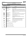
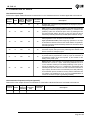
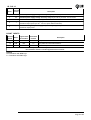
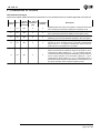
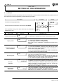
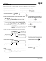
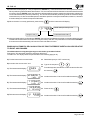
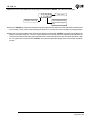
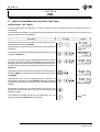
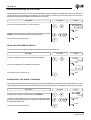
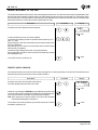
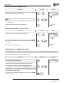
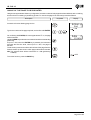
HB 548.10
User’s manual
b54 8
r E L
H10
6
BI-DIRECTIONAL ON/OFF POSITIONER WITH CLEARANCE
RECOVERY AND EXECUTION OF LINES FROM KEYBOARD
HB 548.10
INDEX OF SUBJECTS IN THIS MANUAL
CHAP. 1 - INTRODUCTION
-
Complementarity
References
Responsibility and validity
Description of operation
1-1
1-2
1-3
1-4
CHAP. 2 - OPERATOR / MACHINE INTERFACE
- Keyboard Description
- Inputs Description
- Outputs Description
2-1
2-2
2-3
CHAP. 3 - STARTUP
- Programming (set-up)
- Calibrations
3-1
3-2
CHAP. 4 - USE
- Work programmes and auxiliary functions
- Operation graphs and tables
4-1
4-2
CHAP. 5 - ASSISTANCE
- Inputs and outputs troubleshooting
- How to complete the technical assistance fax form
- Warranty
5-1
5-2
5-3
Page 2 of 28
HB 548.10
CHAPTER 1
INTRODUCTION
1 - 1 SUPPLEMENTARY NATURE OF MANUAL
This manual is to be considered as a supplement to the “Installation, maintenance and servicing manual”, which contains
information on wiring, checking and eliminating faults, start-up and maintenance procedures. This manual gives
instructions on the use and correct programming of the instrument.
You are urged, therefore, to read the manual carefully and, if you have any queries, to contact QEM for further
explanations by sending the assistance fax contained in the manual.
1 - 2 REFERENCES
The documentation on the instruments designed and sold by QEM has been divided into different booklets for effective
and speedy consultation, based on the specific type of information required.
Hardware structure
Installation, maintenance and
servicing manual
Explanation of software.
Basic information on the standard
hardware in the series plus
customisation possibilities.
All the necessary information for
installation, maintenance and
servicing.
This is this manual, giving all the
necessary information for the
understanding and use of the
instrument described. The manual
deals with the instrument software,
with information on the understanding,
programming, calibration and use of
the instrument described.
After installing the instrument,
following the instructions in the
installation, maintenance and
servicing manual, this user manual
gives all the necessary instructions
on the correct use and programming
of the instrument.
This booklet is appended to the user
manual and describes the standard
hardware configuration for the series
of instruments described.
It also gives the standard electrical,
technical
and
mechanical
specifications of the series, together
with the hardware customisation
possibilities in relation to the different
software versions.
All the essential details on the correct
maintenance and installation.
The aim is to provide you with valid
and accurate information for the
manufacture of products of recognised
quality and reliability. It also gives
valid supporting information for
servicing applications with QEM
instruments installed.
User manual
Page 3 of 28
HB 548.10
1 - 3 RESPONSIBILITY AND VALIDITY
RESPONSIBILITY
QEM declines all responsibility for any injury to persons or damage to objects resulting from the failure to observe the
instructions and rules in this manual and the “Installation, maintenance and servicing manual”. It is furthermore specified
that the customer/purchaser is bound to use the instrument according to the instructions provided by QEM and, if any
doubts arise, to send a written query to QEM. Any authorisation for exceptions or substitutions in use, if contested, will
be deemed valid by QEM only if in writing.
The reproduction or handing over of all or part of this manual to third parties without the written authorisation of QEM
is forbidden. Any transgression will result in a claim for compensation for the damages sustained.
All rights deriving from patents or designs are reserved.
QEM reserves the right to make partial or complete modifications to the characteristics of the instruments described
or corresponding documentation.
Objective
The objective of this manual is to give the general rules for the use of the instrument described.
Conservation of parameters
Write down all the instrument setting and programming parameters and keep them in a safe place, to facilitate any future
replacement or servicing operations.
VALIDITY
This manual is applicable to all instrumentation designed, manufactured and tested by QEM with the same order code.
This document is valid in its entirety, barring errors or omissions.
Instrument
release
Manual
Release
6
0
Modifications to manual
New Manual
Date of
modifications
10 / 06 / 04
Page 4 of 28
HB 548.10
1 - 4 DESCRIPTION OF OPERATION
The instrument HB 548.10 is a single-axis ON/OFF bi-directional positioner. The instrument is provided with 99 lines
containing the positioning quotas which can be divided into a number of pages at pleasure. It is provided with a series
of manual functions (introduction of a value on the count, manual movements, etc...) to facilitate the calibration phases
and to allow the operator to intervene on the positioning system. It is allowed the programs execution and work
cycles, with or without count by of working executed. There is the possibility to increase the piece counter
with an input outward applied an expansion card to the base version. The instrument automatically recalculates
the inertia giving very precise positioning even when there are variations in the load, wear, speed, inertia ....
It is also provided with a function that allows movements with a delta quota (∆), useful, for example, when managing a
saw, in the movement of the mobile jig during the cut.
Page 5 of 28
HB 548.10
CHAPTER 2
OPERATOR/MACHINE INTERFACE
2 - 1 KEYBOARD DESCRIPTION
Key
÷
Function
Normal operation:
Data input:
pressed after the “F” key, they select the functions available.
allows entry of data.
Normal operation:
selects the display of the cycle. Impulse pressure selects the
successive display. Continuous pressure selects the previous
display.
scrolling of the various parameters. Impulse pressure selects the
successive parameter. Continuous pressure selects the previous
parameter.
Data input:
Normal operation:
Data input:
chooses the page to be executed.
Inserts or removes the +/- sign. Inserts or removes programme end.
Normal operation:
Data input:
chooses the line to be executed within the selected page.
Inserts the decimal point.
Normal operation:
Data input:
enables the selection of the functions.
Normal operation:
Data input:
in page selection selects the next line without commanding
positioning. Reset the piece count (if enabled)
deletes the input value and reverts to the old value.
Normal operation:
Data input:
when enabled, executes the selected line or page.
stores the datum entered.
During the immediate quota introduction aborted the
posizioned.
Lights up when pages are introduced of program.
Lights up if axis is in tolerance.
Lights up when a page is selected.
Lights up when a line is selected.
Lights up when a function is selected.
Page 6 of 28
HB 548.10
Key
+
+
+
+
+
+
+
+
+
+
Function
Access to password-protected functions.
Introduction of the programme.
Introduction of a value on the count.
Display of the last inertia calculated.
Introduction of blade thickness.
Manual axis movement.
Input and output diagnostics.
Search for preset quota.
Introduction of minimum quota.
Introduction of offset on the count.
Page 7 of 28
HB 548.10
2 - 2 DESCRIPTION OF INPUTS
Characteristics of inputs
Refer to the chapter entitled “Electrical characteristics” in the “Hardware structure” booklet appended to this manual.
Logical Min. time of Polarization
Terminal
Name status of activation
bloach
terminal
activation
(ms)
17
18
I1
I2
ON
ON
50
50
Description
16
Increase line. Increases at any time the line of the page in progress
(change work quota).
16
Start. If input I4 = ON (positioning enabled), commands axis movement
energising movement outputs (forward /reverse) in function of the
positioning quota and remains the piece count. By selecting the line
from the keyboard with the keys line or page, the start can also be
activated by confirming with the key ENTER (when enabled in set-up).
19
I3
ON
50
16
Cycle (impulse mode). Restores the execution of the first line of the
work programme in use. Acquired on the ascent side.
Cycle (continuous mode). When beginning operations, if the input
is activated and remains active for the whole duration of operations,
the work programme will automatically restart from the first line when
the work cycle ends.
20
I4
ON
50
16
Enable positioning. Its activation enables the energising of the
movement outputs; with input I4=OFF positionings are aborted. It can
also be used as an emergency input.
16
Zero impulse enablement. Its specific function depends on the type
of preset search programmed in set-up; upon its activation is
increased the reading of the zero impulse by the encoder for the
loading of the preset quota.
16
Return to zero. When activated, it commands the axis movement to
machine zero or to the D quota. If the set-up parameter "F6" is on
"0", the activation of this input commands positioning at zero quota. If
the set-up parameter "F6" is on "1", positioning is commanded at the
selected quota plus the value of "F6". With a successive activation of
input I2 (start), the axis returns to the selected quota. With positioning
on the selected quota+D, clearance recovery and the inertia band are
not enabled. The positionings are in any event enabled/disabled in
function of the status of input I4 (positioning enabled).
21
22
I5
I6
ON
ON
50
50
Characteristics of expansion of inputs (option E)
Please refer to the chapter “Electric Characteristics” of the leaflet “Hardware Structure” enclosed to this manual.
Terminal
bloach
Name
32
I7
Logical Min. time of Polarization
status of
activation
terminal
activation
(ms)
ON
50
31
Description
Pace Increment. Upon its activation the piece count is increased.
Page 8 of 28
HB 548.10
Name
Terminal
bloach
1
Vac
Instrument power supply voltage. Alternating voltage as per code in your order. 10% 50 / 60 Hz.
2
Vac
Instrument power supply voltage. Alternating voltage as per code in your order. 10% 50 / 60 Hz.
3
GND
Ground connection. A conductor of Æ 4 mm is recommended.
4
+
Transducers positive power supply. Positive voltage supplied by instrument for instrument and
transducers inputs power (12 Vdc - 150 mA, expert different indication).
5
-
Transducers negative power supply. Negative voltage supplied by instrument for instrument and
transducers inputs power.
Description
COUNT INPUTS
Terminal
bloach
Name
13
PHA
N/P
12
Input "phase A" incremental transducer.
14
PHB
N/P
12
Input "phase B" incremental transducer.
15
Z
N/P
12
Input "zero impulse" incremental transducer.
Logical status Polarization
of activation
terminal
Description
For details of the count inputs, refer to the chapter entitled “Electrical characteristics” in
the “Hardware structure” booklet appended to this manual.
Legend
N = Transducer with NPN logic.
P = Transducer with PNP logic.
Page 9 of 28
HB 548.10
2 - 3 DESCRIPTION OF OUTPUTS
Characteristics of outputs
Refer to the chapter entitled “Electrical characteristics” in the “Hardware structure” booklet appended to this manual.
Logical Min. time of Polarization
Terminal
Name status of
activation
bloach
terminal
activation
(ms)
Description
7
U1
ON
C
6
Forward. When this output is energised, it commands the forward
axis movement (the instrument displays the increasing count).
8
U2
ON
C
6
Reverse. When this output is energised, it commands the reverse
axis movement (the instrument displays the decreasing count).
9
U3
ON
C
6
Slow-down. This output reduces the axis speed in proximity of the
positioning point, and commands the passage to slow axis speed.
6
Page end. This is activated when the positioning of the last line of
the page in use is concluded (only if I3=off) and is deactivated at
restart. If input I3 = on (cycle) it is activated for 300 ms when the
positioning of the last page line is concluded.
6
Jolly. If configurated in set-up as tolerance (U = 0), it is activated
when the axis enters the tolerance range for the quota in use. If
configurated as brake enabling (U = 1), it is activated when the
count reaches the inertia range and is disabled by a new positioning
150 ms. before activation of the movement outputs (U1 - U2). If
configurated as brake release (U = 2), it is deactivated when it
reaches the inertia range and is activated by a new positioning 150
ms. before activation of the movement outputs (U1-U2).
10
11
U4
U5
ON
ON
C
C
Page 10 of 28
HB 548.10
CHAPTER 3
SETTING UP FOR OPERATION
3 - 1 SET-UP
As these parameters set the operating mode of the instrument, access is restricted to the installer only. A password must
be entered to access the programming, with the following procedure:
Description
Keyboard
Access the set-up programming.
+
Display
PASS
H .. .
Introduce the access code "548" and confirm with ENTER.
0
= ON
Exit is possible at any time after introducing the password by
pressing the F key.
FUNCTION
Enable input expansion
DISPLAY
AE
Hd
Display mode
FC
Enable the forcing of
count visualization
FP
Decimal figures
FE
Encoder
resolution
Deceleration
Max. 9999
r
L
DESCRIPTION
0
0
0
0
40 0 0 0 0
1234
0 = Expansion not enabled.
1= Expansion is enabled and can be used the piece count.
0 = Normal display.
1 = HDR1 (high definition reading) display
2 = HDR2 (high definition reading) display
N.B. Refer to the “Installation, maintenance and servicing
manual".
0 = the visualization force is disabled
1 = the count visualization is forced, to the value of the current
quota, even if at the end positioning the count is exceded for a
bit the value of the position quota.
2 = the count visualization is forced to the quota in use when the
count of the axis is in the tolerance range..
Select the number of figures after the decimal point (max 3) for
the X axis count display (axis position).
N.B.Entering the number of decimal figures will affect the
DISPLAY of the count; the precision of the positionings depends
on the number of impulses supplied by the transducer.
This parameter sets what the encoder revolution impulses must be
multiplied by to have the length display in the desired unit of quota.
Values from 0.00200 to 4.00000 can be entered, bearing in mind
that the frequency of the P H phases must not exceed the
instrument’s maximum count frequency.
N.B. Refer to the “Installation, maintenance and servicing manual".
This is the distance of the arrival quota at which the axis
deceleration output is activated. See relative paragraph.
N.B. Refer to the “Installation, maintenance and servicing manual"
Page 11 of 28
HB 548.10
FUNCTION
DISPLAY
t
n
t
P
Negative tolerance
Max. 999.9
Positive tolerance
Max. 999.9
Deceleration time
Max. 9.99
Maximum quota
Max. 99999
Enable minimum quota
t
S
r
Clearance recovery
selection
r
o
1 2 34
1 234
00 0
12345
An
Minimum quota
Min. -99999
D minimum positioning
overquota for clearance
recovery
Min. 1
Max. 9999
L
DESCRIPTION
0
12345
A
A
0
1234
Axis positioning negative tolerance limit. The tolerance range is
set by this parameter and the “Positive tolerance” parameter. This
parameter always has one decimal place more than the number of
places programmed in the “FP” parameter, to allow for the QPS
(QEM POSITIONING SYSTEM) function.
N.B. Refer to the “Installation, maintenance and servicing manual"..
Axis positioning positive tolerance limit. The tolerance range is
set by this parameter and the “Negative tolerance” parameter.
This parameter always has one decimal place more than the
number of places programmed in the “FP” parameter, to allow for
the QPS (QEM POSITIONING SYSTEM) function.
N.B. Refer to the “Installation, maintenance and servicing
manual".
Delay time (in seconds) for the activation of the motor forward or
reverse output when positioning enters the deceleration range.
During this time the axis, because of inertia, must not enter the
tolerance range.
This is the maximum quota that the axis can reach; the set value
should also be considered as the maximum limit for the introduction
of working quotas. If clearance recovery is set on "2", this limit is
overcome in the measure set as (quota+overquota).
0 = The value of the minimum quota minima can be introduced
in set-up.
1 = The introduction of the minimum quota is enabled by function
keys "F + 8". In this case, the minimum quota in set-up is used
by the instrument only to calculate the inertia recalculation ranges
(see paragraph "Automatic inertia recalculation").
This is the minimum quota that the axis can reach; the set value
should also be considered as the minimum limit for the introduction
of working quotas. If clearance recovery is set on "1", this limit will
be exceeded by the measure set as (quota-overquota).
0 = Positioning without clearance recovery.
1 = Positioning with forward clearance recovery.
2 = Positioning with reverse clearance recovery.
N.B.Refer to the “Installation, maintenance and servicing manual".
During forward clearance recovery the axis is positioned on: (set
quota - over-quota - inertia) and, after the reverse time, on the set
quota position. During reverse clearance recovery the axis is first
positioned on: (set quota - over-quota - inertia) and, after the
reverse time, on the set quota position. If there is no clearance
recovery or the position does not require clearance recovery, and
the space is less than the over-quota, the instrument will carry out
positioning with clearance recovery.
N.B. The real clearance recovery quota is calculated by adding the
over-quota "OA" to the inertia. If value 0 is introduced, by default
the instrument will insert the value 1.
Page 12 of 28
HB 548.10
FUNCTION
DISPLAY
J
0
Choice of jolly output
AL
Enable blade thickness
b
DESCRIPTION
P
0
0
Load preset
P
123480
Preset quota
Zero impulse
logic status
Enable menu
programming
IO
n
E
Function key ENTER
E
0
0
0
0 = Output U5 behaves as tolerance, being energised if the axis
concludes positioning within the tolerance range.
1 = Output U5 enables the brake, and is energised when the axis
is stopped.
2 = Output U5 acts as brake release, and is de-energised when
the axis is stopped.
When wishing to compensate the thickness of material removed
during the cut, the introduction of the blade thickness must be
enabled. In this case, to set the blade thickness during the
instrument's normal functions, press keys "F + 4".
0 = Blade thickness not enabled.
1 = Blade thickness enabled.
The preset search procedure is carried out:
0 = Loading the count with the preset quota at input I5
deactivation.
1 = Loading the count with the preset quota at input Z activation,
after the axis has reversed direction and input I5 has been
deactivated (sensitive to the down front).
2 = Loading the count with the preset quota at input Z activation,
after input I5 = ON (impulse).
N.B. Refer to the “Installation, maintenance and servicing
manual".
For the preset search procedure, it is the quota that is loaded on
the transducer zero impulse count (according to the method
defined by the type of preset search). A preset quota between the
maximum and minimum quotas can be introduced.
N.B. Refer to the “Installation, maintenance and servicing
manual".
If the encoder generates zero impulse when activating input Z
(PNP), set to 0, otherwise if it generates zero impulse when
disactivating input Z (NPN) set to 1. If thi s parameter i s
programmed correctly, the letter "C" will appear on input
diagnostics when there is no zero impulse.
0 = Access to work quota programming is immediate.
1 = Access to work quota programming is conditioned by a password.
0 = During the choice of the page to be executed, the ENTER
key confirms the line chosen without executing it. When
introducing the immediate quota, it confirms the value introduced
without commanding axis movement.
1 = During the choice of the page to be executed, the ENTER
key confirms the chosen line and executes it. When introducig
the immediate quota, it confirms the value introduced and
commands axis movement. In both cases input I4 (enable
positioning) must be active.
2 =During the choice of the page to be executed, the enter key
confirms the line chosen (between the arrow key is possible
choices another line) without executing it. Another line between
the arrow key can be choice. For to be executed it again, the
enter kex must be to press. When immediate quota is executed,
it confirms the value introduced and ordered the axis movement.
In both cases I4 Input (positioning enable) must be active
Page 13 of 28
HB 548.10
FUNCTION
Check time input I2
and ENTER key
Max. 9.99
DISPLAY
t
S
c
n
o
C
DESCRIPTION
999
0
Memory configuration
Max. 99
Enable offset count
F6 quota (+ / -)
Reverse time
Max. 9,99
Waith time 1
F6
t
i
t
A1
t
A2
0
1234
000
99 9
999
Waith time 2
Enable arrow key
Delay time for
axis leaving
Max. 9.99
Enable I1 Input
AF
t
r
Ar
This is the time, expressed in seconds, for activating the start (I2)
or the ENTER key, when enabled, to execute the selected line.
Determines the number of steps composing a programme. A total
of 99 steps are available; dividing therefore the number of available
steps by the value introduced (number of steps per programme),
youo obtain the number of programmes that can be utilised.
Example:
Cn = 10
N di programmi = 99/10 =9
The steps remaining after the division are added to the last
programme which in this case will have a dimension of 19 steps.
N.B. Every time the "memory configuration" is modified, the
introduced data must be rewritten.
With "Cn"³50 "Page" key is not enable.
0 = Not enabled.
1 = Using keys "F + 9" it is possible to introduce an offset count
value; the value introduced will automatically be added to (or
subtracted from) all the set work quotas.
If "F6" is zero, by activating input I6, the axis moves to zero quota;
if "F6" is other than zero, by activating input I6, the axis positions
on the selected quota + F6 without utilising clearance recovery.
In order to avoid possible mechanical stress, caused by
excessively rapid axis movement reversal, a reverse delay time,
expressed in seconds, can be introduced. This parameter only
affects operation in the event of positioning with clearance
recovery.
This is the wait positioning time after I6 input activation. If during
the wait time execution, input I6 turns OFF, the procedure is
aborted.
This is the wait positioning time on the zero quota or on the delta
quota before to return on the program quota. If the time introduced
has 9,99 value the return on program quota is not delayed by the tA2
time byt controlled bye the I6 input de-activation. With the time Ta2
sets to 0 the return by the delta quota is not enabled bye the I6 input,
but only I2 input or by enter key (if enabled). With tA2 sets to 9,99 or
with tA2 sets to 0 the edventually count piece display is enabled
during delta quota shifting.
0 = the arrow key is not increases the line executed.
1 = the arrow key increases the line executed.
0
It is the delay time for axis leaving that it is activated to the start.
When the time is left the jolly output is deactivated like tolerance.
99 9
0
0 = the I1 input is always enabled to the reading.
1 = the I1 input is not enabled to the reading when it is selected the
first program lin and it is not activated the start yet.
After the start, I1 input is rehabilitated to the reading.
Page 14 of 28
HB 548.10
FUNCTION
DISPLAY
Sn
Choice of memory
DESCRIPTION
0
0= When the instrument is turned off, the automatic working in the
process is memorized and proposed again when the instrument
is started.
1= When the instrument is turned off, the automatic or manual
working in the process is memorized and proposed again when
the instrument is started.
When programming of the last function is terminated, the display in use before entering set-up will reappear.
Page 15 of 28
HB 548.10
3 - 2 CALIBRATION
INTRODUCTION OF A SINGLE FIXED INERTIA VALUE FOR ALL POSITIONINGS.
A) Select manual operation mode.
æ Deactivate input of stop (I4 = OFF).
B) Introduce the access code "123"
æ Type in the sequence
The instrument will display:
PASS
H . ..
æ From the keyboard, introduce the code 123 and confirm with
0
the enter key
E) After confirmation of the code 123, the instrument will display:
æ
By inserting "0" the axis will be considered
8 FASCE
as a single range; by inserting "1", the axis
I n E r 0 will be divided into eight equal ranges.
F) After confirmation of the value "0", the instrument will display:
r ICAL C
InEr 0
+
By inserting "0" the re-calculation is disabled;
by inserting "1", the re-calculation is
enabled,only if the positioning is ended off
out of tolerance;
by inserting “2” the re-calculation is enabled
even when the positioning is ended off in
tolerance.
From the keyboard, introduce the value "0"
(exclusion of the eight ranges) and confirm
with the enter key
æ
Introdurre con la tastiera il valore "0" (esclusione del ricalcolo) confermandolo con il
tasto
æ
Press the key
æ
At this point the operator can introduce the
inertia value using the numerical keys, and
G) After confirmation of the value "0", the instrument will display:
123456
Axis count
I 123456
Range in use (1)
Count relative to the
center of the range in
use
confirming with the enter key
H) The instrument will display:
In
I
Range in use (1)
1 2 34
Inertia value in use
1 2 34
Inertia
introduction
value
N) After confirmation of the value introduced, the instrument will
display:
tA
123
00 0
æ
Set the tolerance activation delay time.
To return to the normal display confirm with
the enter key
This display relates to the "tolerance
activation delay time" setting.
Page 16 of 28
HB 548.10
AUTOMATIC RE-CALCULATION OF A SINGLE FIXED INERTIA VALUE FOR ALL POSITIONINGS.
- First set the "TA" parameter (tolerance activation delay time).
- To obtain the "TA" display follow the points listed below (A÷G).
A) Put the instrument in manual mode.
æ
Deactivate input (I4 = OFF continuous).
B) Introduce the access code "123"
æ
Type in the sequence
æ
From the keyboard, introduce the code 123 and confirm with
The instrument will display:
PASS
H . ..
0
the enter key
C) The instrument will display: 8
FASCE
æ
Introduce the value "0" and confirm with the enter key
D) The instrument will display:
r ICAL C
æ
Introduce the value "0" and confirm with the enter key
123456
æ
Press the key
n 1 2 34
1 2 34
æ
Introduce the value "0" and confirm with the enter key
12 3
æ
Set the tolerance activation delay time. To return to the
normal display confirm with the enter key
E) The instrument will display:
F) The instrument will display: I
InEr 0
InEr 0
1 123456
I
G) The instrument will display: t A
00 0
- Once the "TA" parameter has been set, the automatic inertia calculation can be performed.
H) Return to the automatic inertia calculation by re-introducing the access code 123.
I) After confirmation of the code 123, the instrument will display:
æ
By inserting "0" the axis will be considered
8 FASCE
as a single range; by inserting "1", the axis
I n E r 0 will be divided into eight equal ranges.
L) After confirmation of the value "0", the instrument will display:
r ICAL C
In Er 1
By inserting "0" the re-calculation is disabled;
by inserting "1", the re-calculation is enabled;
by inserting “2” the re-calculation is enabled
even when the positioning is ended off in
tolerance.
M) After confirmation of the value "1", the instrument will display:
Range in use (1)
From the keyboard, introduce the value "0"
(exclusion of the eight ranges) and confirm
with the enter key
æ
From the keyboard, introduce the value
"1" (re-calculation enabled) and confirm
with the enter key
123456
Axis count
I 123456
Count relative to the
center of the range in
use
Page 17 of 28
HB 548.10
N) Deactivate the stop input (I4 = OFF) and press the "ENTER" key. The axis will move to the central point of the stroke.
When positioning has terminated, after the time "TA", the instrument will calculate the inertia value that effects axis
movement. Press "ENTER" again; the axis will re-attempt positioning at the central point of the stroke, adopting the
inertia calculated at the previous positioning. The axis should terminate positioning inside the tolerance range
inserted in set-up. If, after several attempts, the axis fails to position correctly the deceleration, tolerance, tolerance
activation delay time values will require modification.
O) When the axis is correctly positioned, press the key
In
I
and the instrument will display:
1 2 34
Inertia value previously in use
1234
Range in use (1)
Calculated inertia value
P) After the inertia value is confirmed with "ENTER", the instrument will display the tolerance activation delay time (the
installer will choose whether to confirm or modify this value). After the "TA" parameter is confirmed with "ENTER",
the instrument will automatically exit from the inertia calculation function.
ENABLING AUTOMATIC RE-CALCULATION OF EIGHT DIFFERENT INERTIA VALUES RELATIVE
TO EIGHT AXIS RANGES.
To calibrate the axis using the eight range re-calculation, proceed as follows.
First set the "TA" parameter (tolerance activation delay time).
To obtain the "TA" display follow the points listed on the following page (A÷H).
A) Put the instrument in manual mode.
æ
Deactivate input (I4 = OFF continuous).
B) Introduce the access code "123"
æ
Type in the sequence
æ
From the keyboard, introduce the code 123 and confirm with
C) The instrument will display:
PASS
H . ..
0
+
the enter key
D) The instrument will display: 8
FASCE
æ
Introduce the value "0" and confirm with the enter key
E) The instrument will display:
r ICAL C
æ
Introduce the value "0" and confirm with the enter key
1 123456
æ
Press the key
n 1234
æ
Introduce the value "0" and confirm with the enter key
F) The instrument will display:
G)The instrument will display: I
InEr 0
InEr 0
123456
I
1 2 34
Page 18 of 28
HB 548.10
H) The instrument will display:
tA
12 3
æ
00 0
Set the tolerance activation delay time.
To return to the normal display confirm with the enter key
I) Return to the automatic inertia calculation by re-introducing the access code 123.
L) After confirmation of the code 123, the instrument will display:
æ
By inserting "0" the axis will be considered
8 FASCE
as a single range; by inserting "1", the axis
I n E r 1 will be divided into eight equal ranges.
M) After confirmation of the value "0", the instrument will display:
By inserting "0" the re-calculation is disabled;
by inserting "1", the re-calculation is enabled;
I n E r 1 by inserting “2” the re-calculation is enabled
even when the positioning is ended off in
tolerance.
N) After confirmation of the value "1", the instrument will display:
r ICAL C
From the keyboard, introduce the value "1"
(enabling the eight ranges) and confirm
with the enter key
æ
From the keyboard, introduce the value "1"
(re-calculation enabled) and confirm with
the enter key
123456
Axis count
I 123456
Range in use (1÷8)
Count relative to the
center of the range in
use
O) Deactivate the stop input (I4 = OFF) and press the "ENTER" key. The axis will move to the central point of the first
range. When positioning has terminated,after the time "TA", the instrument will calculate the inertia value that effects
axis movement within the first range. Press "ENTER" again; the axis will re-attempt positioning at the center of the
first range, adopting the inertia calculated at the previous positioning. The axis should terminate positioning inside
the tolerance range inserted in set-up. If, after several attempts, the axis fails to position correctly the deceleration,
tolerance, tolerance activation delay time values will require modification.
P)
When the axis is correctly positioned, press the key
In
I
Range in use (1÷8)
and the instrument will display:
1234
Inertia value previously in use
1 2 34
Calculated inertia value
The installer may modify this value (if considered necessary) or confirm with the
key.
Page 19 of 28
HB 548.10
Q) After the inertia value relative to the first range is confirmed with "ENTER", the instrument will display:
123456
Axis count
2 123456
Range in use (1÷8)
Count relative to the
center of the range in
use
R) After the "ENTER" key has been pressed, the instrument positions the axis for the inertia calculation realative to the
second range. This is carried out by repeating points M, N, O. Proceed with inertia calculation for all eight ranges.
S) When the inertia value relative to the eighth range has been confirmed with "ENTER", the instrument will display the
tolerance activation delay time. The "TA" may be different from the value set before calibration was started, if the
instrument decided that the value required modification in order to provide a more precise inertia calculation. After
the "TA" parameter is confirmed with "ENTER", the instrument will automatically exit from the inertia calculation
function.
Page 20 of 28
HB 548.10
CHAPTER 4
USE
4 - 1 WORK PROGRAMMES AND AUXILIARY FUNCTIONS
INTRODUCING THE PAGES
The work programme is composed of a certain number of pages, defined with the set-up parameter "Memory
configuration".
For each page it is possible to set a positioning line (preselection) and the number of operations to be made once the
set quota has been reached (totaliser).
Description
Keyboard
If programming is protected by a password (see set-up), type in the
value "456" and confirm with ENTER.
If programming is not protected by a password, no code needs to be
introduced.
The operator can introduce the page to be programmed and confirm
it using the ENTER key.
On confirming the page, the upper display will indicate the number of
the page. The bottom left display will indicate the number of the line
being programmed while the bottom right display will show the quota;
the opoerator can introduce the required quota and confirm with the
ENTER key.
Pr o Gr
+
P A S4 5 6
= ON
Pr o Gr
÷
P AG10
PAG 10
÷
1 123456
Proposes introduction of page end. If wishing to introduce page end
press the "PAGE" key. If wishing to continue programming, confirm
with ENTER.
Proposes the second line of the selected page; the operator can
introduce the quota and confirm with ENTER. Introduction of page end
is proposed; programming can continue until completing the steps
available.
Display
-
PAG 10
1 123456
÷
PAG 10
2
1234
By pressing the arrow key, the various lines of the page can be
scrolled from the first to the last, or up to the line in which page end
has been inserted.
It is possible to exit page introduction by pressing key "F"; only
values confirmed with ENTER will be memorised.
= OFF
Page 21 of 28
HB 548.10
VALUE INTRODUCTION ON THE COUNT
The instrument offers functions for axis manual management and as an aid during calibration phases. The value of the
count shown on the instrument (axis position) can be modified by introducing the desired value. This function is
particularly useful during installation and calibration procedures.
Description
Keyboard
Access the value introduction on a count function.
+
Display
I nC o u n t
123456
= ON
The operator may introduce the required count value and confirm with
ENTER. The instrument will show the value introduced.
÷
= OFF
To exit the function press key "F".
RECALCULATED INERTIA DISPLAY
This way, the last inertia value calculated is displayed (with the last positioning).
Description
Keyboard
Access the display function for the last inertia calculated.
+
Display
In Er
1 2 34
= ON
If not set, the automatic recalculation is displayed.
Err or
To exit the function, press key "F".
= OFF
INTRODUCING THE BLADE THICKNESS
The quantity of material removed during the cut can be compensated by inserting the thickness of the blade in use. The
value introduced will be added to all the positioning quotas so that they are increased by the thickness of the blade.
Description
Keyboard
Access the function for introducing the blade thickness, type in the
thickness of the blade in use and confirm with ENTER.
The value of the blade thickness can also be modified during the
execution of a programme; the newe value introduced will be used for
the remaining positionings.
To exit the function press key "F".
+
Display
SL A M A
2 34
÷
= ON
= OFF
Page 22 of 28
HB 548.10
MANUAL MOVEMENT OF THE AXIS
The instrument offers functions for the manual management of the axis. The axis can be moved by the keyboard in both
directions and at two different speeds. When the manual axis movement function is selected, key 7 allows the axis to
be moved "back" (count decreases), while with key 9 it is possible to move the axis "forward" (count increases). Key
8 allows the selection of manual movement speed (slow or fast).
Description
Access the function relative to axis movement.
Keyboard
Display
+
F
nAn
123456
= ON
In manual mode, keys 7,8, and 9 are enabled.
The bottom left display shows the speed selected with key 8 (L =
slow, F = fast).
By pressing key 7 the axis moves back and movement stops when
the key is released.
By pressing key 9 the axis moves foreward and movement stops
when the key is released.
The bottom right displays show the count (axis position).
During manual movements, the set minimum and maximum limits
are enabled (set-up).
= OFF
To exit the function, press key "F".
PRESET QUOTA SEARCH
The instrument offers functions for axis manual management. Preset quota search can also be controlled from the
keyboard (for preset quota search see the relative section).
Description
Access the function for the preset quota search.
The lower displays will show the count value.
Keyboard
+
Display
rPr
ESEt
1 70
= ON
At start or on pressing the ENTER key (if enabled in set-up) the axis
moves in search of the command for loading the preset quota (setup function) and when activated, the preset quota is loaded.
N.B. After carrying out a preset search, this cannot be repeated
unless after restarting the instrument.
To exit the function and to abort the procedure if this has not been
terminated, press key "F".
= OFF
Page 23 of 28
HB 548.10
INTRODUCING THE MINIMUM QUOTA
Description
Keyboard
Access the function for the introduction of the minimum quota (if its
introduction has been enabled in set-up).
+
Display
Qni ninA
123456
= ON
The operator can introduce the minimum quota value and confirm with
ENTER.
N.B. The quota introduced must be greater than the minimum quota
set in set-up.
÷
= OFF
To exit minimum quota insertion, press key "F".
INTRODUCING OFFSET ON THE COUNT
Description
Keyboard
Access the function for introducing the offset count.
+
Display
OFFCont
3456
= ON
The operator can introduce the offset value and confirm with ENTER.
N.B. This value remains set even after switching off or a preset
search.
÷
= OFF
To exit the function, press key "F".
POSITIONING AT AN IMMEDIATE QUOTA
The instrument offers functions for manual axis management. The axis can be automatically positioned at a quota other
than the work quotas that can be selected from the existing programmes. This function speeds up considerably all those
positioning operations differing from normal operations.
Description
Keyboard
Using one of the numerical keys, select the display relative to the
introduction of an immediate quota.
The upper displays show the count (axis position), while the lower
displays show the immediate positioning quota introduced.
The operator can introduce the required immediate quota.
On confirming the introduced value with ENTER (if in set-up the
parameter "E" is on 1), the instrument positions the axis at the quota
introduced. If in set-up parameter "E" =0, the axis start will be
commanded by the start input.
Display
$
234567
123
÷
To exit without executing the immediate quota, press the "CLEAR"
key or the "F" key.
Page 24 of 28
HB 548.10
CHOICE OF THE PAGE TO BE EXECUTED
Using the set-up parameter "Memory configuration" a certain number of work pages have been defined, each containing
a series of lines consisting of positioning quotas. To choose the page to be executed, proceed as follows:
Description
Keyboard
Display
Access the function allowing page choice.
SCEL t A
PAG
7
= ON
Type in the number of the page required, and confirm with ENTER.
On confirming with ENTER, if the set-up parameter "E" =1, the page
will be executed.
Use the CLEAR key to select the successive line without commanding
positioning.
If input I4 = ON, when the ENTER key is pressed, the instrument
executes the first line while, when input I4 = OFF, the page is
blocked.
The arrow key is used to scroll the various lines of the page from the
first to the last or up to the line in which page end has been inserted.
N.B. The selected lines will be executed if I4 = ON (positioning
enabled).
÷
1
PAG
7
123456
= OFF
To exit the function, press the PAGE key.
Page 25 of 28
HB 548.10
CHOICE OF THE PAGE TO BE EXECUTED
Description
Keyboard
Display
To select a specific line of the programme, access the line choice
function.
SCEL t A
3 r IGA 9
= ON
Type in the number of the line required within the page selected with
the LINE key and confirm with ENTER.
The flashing quota indicates that the value can be modified or
executed by the operator using ENTER (when enabled in set-up).
On confirming with ENTER the quota stops flashing to show that
execution is under way.
÷
÷
r
IGA
7
3 234567
For the quota to be modified again, press the CLEAR key; the current
positioning will be aborted and the quota will flash again.
The modified value will not be memorised and a new line display will
show once more the value programmed in page programming.
By pressing the arrow key, the various page lines can be scrolled from
first to last or up to the line in which page end was inserted.
N.B. The lines selected will be executed if input I4 = ON (positioning
enabled).
If negative quotas are introduced the maximum programmable
value is "-99999".
To exit the function, press the LINE key.
= OFF
DISPLAYS
Description
Lower left hand display
Number of the selected line.
Upper right hand display
Count.
Lower right hand display
Preselection.
Parametro di set-up "AE" impostato a "1" e posizionamento in fascia
di tolleranza.
Upper right hand display
Number of quota selected.
Lower right hand display
Count.
Lower right hand display
Piece counter.
Keyboard
Display
123456
11
23467
123456
11 C 1234
Page 26 of 28
HB 548.10
4 - 2 OPERATION GRAPHS AND TABLES
PRESET SEARCH
"Mode 0" - Loading the preset quota using the zero impulse enabling input.
The preset quota loading command is only provided by the zero impulse enabling input.
Once the preset search procedure has started, the axis moves towards the sensor connected to the zero
impulse enabling input; when, during the stroke, the axis activates this input reversing the direction and
decelerating.
With the deactivation of the zero impulse enabling input, the preset quota is loaded on the instrument count.
With this procedure, the preset quota loading condition is that the enabling input has been activated and
then successively deactivated.
"Mode 1" - Loading the preset quota using the zero impulse and the zero impulse enabling input with
inversion.
The preset quota loading command is provided by the transducer zero impulse. When an encoder provides
a zero impulse on each revolution, the zone in which the axis acquires the zero impulse must be
determined; the zero impulse enabling input is used for this purpose.
Once the preset search procedure has started, the axis moves towards the sensor connected to the zero
impulse enabling input; when, during the stroke, the axis activates this input reversing the direction and
decelerating.With the deactivation of the enabling input the instrument is ready to acquire the zero impulse:
with the first zero impulse provided by the transducer, the preset quota is loaded on the instrument count.
With this procedure, the preset quota loading condition is that the enabling input has been activated and
then successively deactivated and a zero impulse has been acquired.
"Mode 2" - Loading the preset quota using the zero impulse and the zero impulse enabling input without
inversion.
The preset quota loading command is provided by the transducer zero impulse. When an encoder provides
a zero impulse on each revolution, the zone in which the axis acquires the zero impulse must be
determined; the zero impulse enabling input is used for this purpose.
Once the preset search procedure has started, the axis moves towards the sensor connected to the zero
impulse enabling input; when, during the stroke, the axis activates this input, maintaining the direction and
decelerating.
The instrument is ready to acquire the zero impulse: with the first zero impulse provided by the transducer,
the preset quota is loaded on the instrument count.
With this procedure, the preset quota loading condition is that the enabling input has been activated and
then successively deactivated and a zero impulse has been acquired. In order to avoid errors, the enabling
input activation space must be less than the distance covered by the axis during one encoder revolution.
If not, the zero impulse can be acquired at two different points.
"Mode 3" - Loading the preset quota using the input.
With this procedure preset search is not enabled. The preset quota loading command is provided by the
activation of the preset search start input.
Page 27 of 28
HB 548.10
CHAPTER 5
ASSISTANCE
5 - 1 INPUT AND OUTPUT TROUBLESHOOTING
The instrument provides troubleshooting for the input and digital output logic status; according to the numbers displayed,
it is possible to understand whether an input arrives at the instrument and if an output has been excited.
The top line of the display refers to the inputs status; if number 1 is displayed, this means that input 1 has been activated;
if number 2 is shown, this means that input 2 has been activated and so on. Input Z (transducer zero impulse) is signalled
with an A; if this is shown, there is no zero impulse; if not shown, the zero impulse is supplied to the instrument.
The last line of the displays refers to the logic status of the digital outputs. The same correspondence (each number
corresponds with its equal output); for example, the presence of the number 4 indicates that the instrument is energising
output 4.
Description
Access the troubleshooting function. The input (I) and output (O)
status will be displayed.
Keyboard
+
Display
I 123456
01 23457c
= ON
To exit the function, press "F".
= OFF
5 - 2 HOW TO COMPLETE THE TECHNICAL ASSISTANCE FAX FORM
If we are to provide you with a speedy, efficient and high-quality service, we need your help.
If ever you need the assistance of QEM in dealing with any technical problems that may arise in your applications
and, even though all the instructions in the “Installation, maintenance and servicing” manual have been
followed, the problem persists, we invite you to fully complete the fax form enclosed with the installation,
maintenance and servicing manual and send it to the QEM assistance office.
In this way, our service engineers will have all the essential information for the understanding of your problem
(thus avoiding long and costly telephone calls).
In thanking you for co-operation, we wish you all the best in your work.
NOTE
If ever you have to send an instrument to us for repair, please read the points below carefully.
- If possible, use the original packaging. In any event, the packaging must protect the instrument from knocks during
its journey.
- Enclose a detailed description of the problem that has occurred, along with the part of the wiring diagram where the
instrument is located, in the package. If the problem involves data storage, enclose the instrument set-up
programming (set-up, work quotas, auxiliary parameters ...).
- If necessary, ask us specifically for an estimate on the repairs. If no estimate is requested, the cost will be calculated
on completion.
- Our service engineers will give priority to instruments that are sent to in accordance with the instructions in these
notes.
5 - 3 WARRANTY
The warranty conditions are as stated in the general conditions of sale.
This product is an electronic instrument and, therefore, should not be considered a machine. As a consequence,
it is not subject to the requirements of EEC Directive 89/392 (Machine Directive). For this reason, we affirm that if
the QEM instrument is used as a component of a machine, it may not be turned on if the machine does not satisfy
the requirements of the Machine Directive.
The instruments marking does not relieve the customer from fulfilling the obligations of the law relative
to the finished product.
Page 28 of 28