1
PREFACE
14 June 2006
MAN0356-04
User Manual for the
HE500TIU050
HE500TIU1XX
HE500TIU20X
HENX2XXTXXX
HE500TIU3XX
HE500TIU4XX
HE500TIU5XX
HE500TIU6XX
And SmartStack Modules
Operator Station
Hardware Manual
Fourth Edition
8th August 2005
MAN0356-04
Page 1 of 70
PREFACE
14 June 2006
MAN0356-04
PREFACE
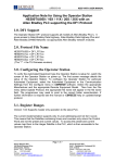
This manual explains how to use the Horner APG Operator Station Hardware Modules (HE500TIU050,
HE500TIU10X, HE500TIU11X, HENX2XXTXXX, HE500TIU3XX, HE500TIU4XX, HE500TIU5XX,
HE500TIU6XX and SmartStack Modules).
Copyright © 2000 Horner APG, LLC., 640 North Sherman Drive, Indianapolis, Indiana 46201-3899. All
rights reserved. No part of this publication may be reproduced, transmitted, transcribed, stored in a
retrieval system, or translated into any language or computer language, in any form by any means,
electronic, mechanical, magnetic, optical, chemical, manual or otherwise, without the prior agreement and
written permission of Horner APG, LLC.
Information in this document is subject to change without notice and does not represent a commitment on
the part of Horner APG, LLC.
Windows® 95, Windows® 98, Windows® NT, Windows® 2000 and Windows® XP are registered
trademarks of Microsoft Corporation.
DeviceNet is a trademark of Open DeviceNet Vendors Association (ODVA).
Profibus is a trademark of Siemens.
Cscape, CsCAN, and SmartStack are trademarks of Horner APG, LLC.
For user manual updates, contact Horner APG, Technical Support
Division, at (317) 916-4274 (USA), or +353-21-4321266 (Europe) or visit
our web-site at www.horner-apg.com.
LIMITED WARRANTY AND LIMITATION OF LIABILITY
Horner APG, LLC. ("HE-APG") warrants to the original purchaser that the Operator Station manufactured by HE is free from defects
in material and workmanship under normal use and service. The obligation of HE-APG under this warranty shall be limited to the
repair or exchange of any part or parts which may prove defective under normal use and service within two (2) years from the date
of manufacture or eighteen (18) months from the date of installation by the original purchaser whichever occurs first, such defect to
be disclosed to the satisfaction of HE-APG after examination by HE-APG of the allegedly defective part or parts. THIS WARRANTY
IS EXPRESSLY IN LIEU OF ALL OTHER WARRANTIES EXPRESSED OR IMPLIED INCLUDING THE WARRANTIES OF
MERCHANTABILITY AND FITNESS FOR USE AND OF ALL OTHER OBLIGATIONS OR LIABILITIES AND HE-APG NEITHER
ASSUMES, NOR AUTHORIZES ANY OTHER PERSON TO ASSUME FOR HE-APG, ANY OTHER LIABILITY IN CONNECTION
WITH THE SALE OF THE Operator Station. THIS WARRANTY SHALL NOT APPLY TO THE Operator Station OR ANY PART
THEREOF WHICH HAS BEEN SUBJECT TO ACCIDENT, NEGLIGENCE, ALTERATION, ABUSE, OR MISUSE. HE MAKES NO
WARRANTY WHATSOEVER IN RESPECT TO ACCESSORIES OR PARTS NOT SUPPLIED BY HE. THE TERM "ORIGINAL
PURCHASER", AS USED IN THIS WARRANTY, SHALL BE DEEMED TO MEAN THAT PERSON FOR WHOM THE Operator
Station IS ORIGINALLY INSTALLED. THIS WARRANTY SHALL APPLY ONLY WITHIN THE BOUNDARIES OF THE
CONTINENTAL UNITED STATES.
In no event, whether as a result of breach of contract, warranty, tort (including negligence) or otherwise, shall HE-APG or its
suppliers be liable of any special, consequential, incidental or penal damages including, but not limited to, loss of profit or revenues,
loss of use of the products or any associated equipment, damage to associated equipment, cost of capital, cost of substitute
products, facilities, services or replacement power, down time costs, or claims of original purchaser's customers for such damages.
To obtain warranty service, return the product to your distributor with a description of the problem, proof
of purchase, post paid, insured and in a suitable package.
Page 2 of 70
PREFACE
14 June 2006
MAN0356-04
ABOUT PROGRAMMING EXAMPLES
Any example programs and program segments in this manual or provided on accompanying diskettes are
included solely for illustrative purposes. Due to the many variables and requirements associated with any
particular installation, Horner APG, LLC cannot assume responsibility or liability for actual use based on
the examples and diagrams. It is the sole responsibility of the system designer utilising the Operator
Station to appropriately design the end system, to appropriately integrate the Operator Station and to
make safety provisions for the end equipment as is usual and customary in industrial applications as
defined in any codes or standards which apply.
NOTE: The programming examples shown in this manual are illustrative
only. Proper machine operation is the sole responsibility of the system
integrator.
DECLARATION OF EMC CONFORMITY
Manufacturer's Name:
Manufacturer's Address:
Horner Ireland Ltd.
Unit 1, Centrepoint, Centre Park Road, Cork, Ireland
Declares that the products
Models: HE500TIU050, HE500TIU100, HE500TIU101, HE500TIU102,
HE500TIU110, HE500TIU111, HE500TIU200, HE500TIU201 and
HE500TIU202.
Conforms to the following EMC standards:
EMC:
EN 55 022, Radiated and Conducted Emissions
EN 50 082-1, RF, EFT/EFB, ESD Immunity
Supplementary Information:
The above conformity only relates to the products in a stand-alone capacity. The products are used as
part of a system and are therefore classified as a component. As a component, the products are
prohibited by EC regulations to carry a CE Mark for EMC conformity. Static discharge tests only apply to
normal operation of the keyboards via the front panel. We would stress that the use of our products
within your system, while helping to ensure compliance of your system to the same directives, do not
necessarily guarantee that compliance will be achieved. We would also like to point out that the
interpretation of the law concerning CE marking and its application to sub-assemblies and components is
open to interpretation.
Date: 31 Mar 1999
Page 3 of 70
PREFACE
14 June 2006
MAN0356-04
REVISION TO THIS MANUAL
This version (MAN0356-05) of the Tiu Range hardware manual contains the following revisions, additions
or deletions:
Inserted Section 7 Tiu4xx Hardware Guide
Inserted Section 8 Tiu5xx Hardware Guide
Inserted Section 9 Tiu6xx Hardware Guide
Modified Tiu3xx specific information in Section 7 Communications to include Tiu4xx /Tiu5xx/Tiu6xx
Modified TIU4/5/6xx specific information in Chapters 7,8,9 to include Hardware Specifications and Serial
Port Details
Inserted Section 6 HENX2XXTXXX for NX Hardware Guide
Modified Chapter/Section numbers to allow inclusion of Chapter on NX
Page 4 of 70
PREFACE
14 June 2006
MAN0356-04
TABLE OF CONTENTS
PREFACE ..................................................................................................................................................... 2
LIMITED WARRANTY AND LIMITATION OF LIABILITY............................................................................. 2
ABOUT PROGRAMMING EXAMPLES ........................................................................................................ 3
DECLARATION OF EMC CONFORMITY .................................................................................................... 3
REVISION TO THIS MANUAL...................................................................................................................... 4
CHAPTER 1: INTRODUCTION .................................................................................................................... 8
1.1
Scope.............................................................................................................................................. 8
1.2
Equipment Needed ....................................................................................................................... 12
1.3
Technical Specifications ............................................................................................................... 14
1.4
Upgrade Revision Software & Firmware ...................................................................................... 15
1.4.1
Scope .................................................................................................................................... 15
1.4.2
Software Upgrade ................................................................................................................. 15
1.4.3
Firmware Upgrade................................................................................................................. 15
CHAPTER 2: HE500TIU050 ....................................................................................................................... 16
2.1
Scope............................................................................................................................................ 16
2.2
HE500TIU050 Button Selection Actions....................................................................................... 16
2.3
HE500TIU050 Contrast Adjustment ............................................................................................. 16
2.4
HE500TIU050 Ports ..................................................................................................................... 17
2.4.1
HE500TIU050 Configuration of the RS-485 Port .................................................................. 17
2.5
HE500TIU050 Dimensions ........................................................................................................... 18
CHAPTER 3: HE500TIU100/101/102/103 .................................................................................................. 20
3.1
Scope............................................................................................................................................ 20
3.2
HE500TIU10X Button Selection Actions ...................................................................................... 20
3.3
HE500TIU10X Contrast Adjustment............................................................................................. 20
3.4
HE500TIUX Rear View................................................................................................................. 21
3.5
HE500TIU100 Ports ..................................................................................................................... 21
3.5.1
HE500TIU10X Configuration of the RS-485 Port.................................................................. 22
3.6
HE500TIU10X Dimensions........................................................................................................... 23
CHAPTER 4: HE500TIU110/111/112/113 .................................................................................................. 24
4.1
Scope............................................................................................................................................ 24
4.2
HE500TIU11X Button Selection Actions ...................................................................................... 24
4.3
HE500TIU11X Contrast Adjustment............................................................................................. 24
4.4
HE500TIU11X Rear View............................................................................................................. 25
4.5
HE500TIU110 Ports ..................................................................................................................... 25
4.5.1
HE500TIU11X Configuration of the RS-485 Port.................................................................. 26
4.6
HE500TIU11X Dimensions........................................................................................................... 27
CHAPTER 5: HE500TIU200/201/202/203 .................................................................................................. 28
5.1
Scope............................................................................................................................................ 28
5.2
HE500TIU20X Button Selection Actions ...................................................................................... 28
5.3
HE500TIU20X Contrast Adjustment............................................................................................. 29
5.4
HE500TIU20X Rear View............................................................................................................. 29
5.5
HE500TIU20X Ports ..................................................................................................................... 29
6.5.1
HE500TIU20X Configuration of the RS-485 Port.................................................................. 31
5.6
HE500TIU20X Dimensions........................................................................................................... 31
CHAPTER 6: HENX2XXTXXX.................................................................................................................... 32
6.1
Scope............................................................................................................................................ 32
6.2
Button Selection Actions............................................................................................................... 33
6.3
Contrast Adjustment ..................................................................................................................... 33
6.4
Rear View ..................................................................................................................................... 33
6.5
Ports ............................................................................................................................................. 34
6.5.1
HE500TIU20X Configuration of the RS-485 Port.................................................................. 36
6.6
Dimensions ................................................................................................................................... 36
Page 5 of 70
PREFACE
14 June 2006
MAN0356-04
CHAPTER 7: HE500TIU300/301/302/303/310/311/312/313/320/321/322/323.......................................... 37
7.1
Scope............................................................................................................................................ 37
7.2
HE500TIU3XX Touch Key Pad .................................................................................................... 37
7.3
HE500TIU3XX Contrast Adjustment ............................................................................................ 37
7.4
HE500TIU3XX Rear View ............................................................................................................ 38
7.5
HE500TIU3XX Serial Ports .......................................................................................................... 38
7.6
HE500TIU3XX Dimensions .......................................................................................................... 39
7.7
SPECIFICATIONS........................................................................................................................ 39
CHAPTER 8: HE500TIU4XX ...................................................................................................................... 41
8.1
Scope............................................................................................................................................ 41
8.2
HE500TIU4XX Touch Key Pad .................................................................................................... 41
8.3
HE500TIU4XX Rear View ............................................................................................................ 41
8.4
HE500TIU4XX Serial Ports .......................................................................................................... 42
8.5
HE500TIU4XX Dimensions .......................................................................................................... 43
8.6
SPECIFICATIONS........................................................................................................................ 44
CHAPTER 9: HE500TIU5XX ...................................................................................................................... 46
9.1
Scope............................................................................................................................................ 46
9.2
HE500TIU5XX Touch Key Pad .................................................................................................... 46
9.3
HE500TIU5XX Rear View ............................................................................................................ 46
9.4
HE500TIU5XX Serial Ports .......................................................................................................... 47
9.5
HE500TIU5XX Dimensions .......................................................................................................... 48
9.6
SPECIFICATIONS........................................................................................................................ 49
CHAPTER 10: HE500TIU6XX .................................................................................................................... 51
10.1
Scope ........................................................................................................................................ 51
10.2
HE500TIU6XX Touch Key Pad................................................................................................. 51
10.3
HE500TIU6XX Rear View......................................................................................................... 51
10.4
HE500TIU6XX Serial Ports....................................................................................................... 52
10.5
HE500TIU6XX Dimensions....................................................................................................... 53
10.6
Specifications ............................................................................................................................ 54
CHAPTER 11: COMMUNICATIONS .......................................................................................................... 56
11.1
PC to Operator Station Communications.................................................................................. 56
11.2
Automation Equipment (AE) Communications Connections .................................................... 56
10.2.1
Recommended Automation Equipment Communication Cables .......................................... 56
11.3
RS-232 Connection................................................................................................................... 56
11.4
RS-422/485 Four-Wire.............................................................................................................. 57
11.5
RS-485 Two-Wire...................................................................................................................... 58
11.6
Current Loop ............................................................................................................................. 59
CHAPTER 12: GETTING STARTED .......................................................................................................... 60
12.1
Self-Test (TIU050, TIU1xx, TIU2xx).......................................................................................... 60
12.1.1
Contrast Band ....................................................................................................................... 60
12.1.2
Display Test........................................................................................................................... 60
12.1.3
Keyboard Test ....................................................................................................................... 60
12.1.4
RAM Test............................................................................................................................... 60
12.1.5
Serial Loop-back Tests.......................................................................................................... 60
12.2
Self-Test (TIU4xx,TIU5xx, TIU6xx) ........................................................................................... 61
12.3
Updating the Protocol ............................................................................................................... 61
12.4
Updating the Operating System................................................................................................ 62
CHAPTER 13 : NETWORKS ...................................................................................................................... 63
13.1
Scope ........................................................................................................................................ 63
13.2
Controller Area Network (CAN) Overview ................................................................................ 63
13.2.1
CAN Features........................................................................................................................ 63
13.3
CsCAN Network Overview........................................................................................................ 63
13.3.1
CsCAN Network Features ..................................................................................................... 63
13.3.2
CsCAN Network Operation ................................................................................................... 63
13.4
DeviceNet Overview ................................................................................................................. 64
13.4.1
DeviceNet Features............................................................................................................... 64
Page 6 of 70
PREFACE
14 June 2006
MAN0356-04
13.4.2
DeviceNet Protocol................................................................................................................ 65
13.4.3
DeviceNet Operation ............................................................................................................. 65
13.5
CAN Wiring Rules ..................................................................................................................... 66
13.6
Profibus ..................................................................................................................................... 67
13.6.1
Profibus Wiring ...................................................................................................................... 67
CHAPTER 14: SMARTSTACK ™ ............................................................................................................... 69
14.1
Scope ........................................................................................................................................ 69
14.2
Installing and Removing a SmartStack Module ........................................................................ 69
14.2.1
Installing SmartStack Modules .............................................................................................. 69
14.2.2
Removing SmartStack Modules ............................................................................................ 69
Page 7 of 70
CH.1: INTRODUCTION
14 June 2006
MAN0356-04
CHAPTER 1: INTRODUCTION
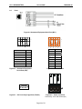
1.1
Scope
The Operator Station (HE500TIU050/10X/11X/2XX/3XX,4XX,5XX,6XX & HENX2XXTXXX) is an Operator
Station (OS) that provides extensive monitoring and control in an extremely small package. The Operator
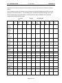
Station “OS” product line offers four distinct categories of products as described in Table 1.1.
Table 1.1 – Operator Station (OS) Product Line
Model
Description
TIU050: Text Only
HE500TIU050-001
2 lines x 20 characters.
HE500TIU050-002
2 lines x 20 characters with Real Time Clock.
TIU10x: Text / Semi-Graphics
HE500TIU100-01
8 Lines x 20 Characters plus 128 x 64 pixels.
HE500TIU100-02
8 Lines x 20 Characters plus 128 x 64 pixels with Real Time Clock.
8 Lines x 20 Characters plus 128 x 64 pixels with Current Loop.
HE500TIU100-03
HE500TIU100-04
8 Lines x 20 Characters plus 128 x 64 pixels with Current Loop and Real
Time Clock.
HE500TIU100-05
8 Lines x 20 Characters plus 128 x 64 pixels with Stud Type Metalwork
8 Lines x 20 Characters plus 128 x 64 pixels with wide temperature
HE500TIU100-06
display.
8 Lines x 20 Characters plus 128 x 64 pixels with Bezel
HE500TIU100-07
HE500TIU100-09
8 Lines x 20 Characters plus 128 x 64 pixels with no metal and dill
connectors
8 Lines x 20 Characters plus 128 x 64 pixels with CsCAN Network.
HE500TIU101-01
8 Lines x 20 Characters plus 128 x 64 pixels with CsCAN Network and
HE500TIU101-02
Real Time Clock.
HE500TIU102-01
8 Lines x 20 Characters plus 128 x 64 pixels with Profibus™ Network.
HE500TIU102-02
8 Lines x 20 Characters plus 128 x 64 pixels with Profibus™ Network
and Real Time Clock.
HE500TIU103-01
8 Lines x 20 Characters plus 128 x 64 pixels with DeviceNet™ Network.
HE500TIU103-02
8 Lines x 20 Characters plus 128 x 64 pixels with DeviceNet™ Network
and Real Time Clock.
TIU11X: Text / Semi Graphics with Numeric Keypad
8 Lines x 20 Characters plus 128 x 64 pixels plus a Numeric keypad.
HE500TIU110-01
8 Lines x 20 Characters plus 128 x 64 pixels plus a Numeric keypad with
HE500TIU110-02
Real Time Clock.
8 Lines x 20 Characters plus 128 x 64 pixels plus a Numeric keypad with
HE500TIU110-03
Current Loop.
HE500TIU110-04
8 Lines x 20 Characters plus 128 x 64 pixels plus a Numeric keypad with
Current Loop and Real Time Clock.
HE500TIU110-05
8 Lines x 20 Characters plus 128 x 64 pixels with Stud Type Metalwork.
HE500TIU110-06
8 Lines x 20 Characters plus 128 x 64 pixels with wide temperature
display.
HE500TIU110-07
8 Lines x 20 Characters plus 128 x 64 pixels with Bezel
HE500TIU110-09
8 Lines x 20 Characters plus 128 x 64 pixels with no metal and dill
connectors
HE500TIU111-01
8 Lines x 20 Characters plus 128 x 64 pixels plus a Numeric keypad with
CsCAN Network.
HE500TIU111-02
8 Lines x 20 Characters plus 128 x 64 pixels plus a Numeric keypad with
CsCAN Network and Real Time Clock.
HE500TIU112-01
8 Lines x 20 Characters plus 128 x 64 pixels plus a Numeric keypad with
Profibus™ Network.
HE500TIU112-02
8 Lines x 20 Characters plus 128 x 64 pixels plus a Numeric keypad with
Profibus™ Network and Real Time Clock.
HE500TIU113-01
8 Lines x 20 Characters plus 128 x 64 pixels with DeviceNet™ Network.
8 Lines x 20 Characters plus 128 x 64 pixels with DeviceNet™ Network
HE500TIU113-02
and Real Time Clock.
Page 8 of 70
CH.1: INTRODUCTION
14 June 2006
MAN0356-04
TIU20X: Text / Full Graphics with Numeric / Function Keypad
HE500TIU200
16 Lines x 40 Characters plus 240 x 128 pixels plus a Numeric keypad /
Function keypad. Optional SmartStack I/O.
HE500TIU201
16 Lines x 40 Characters plus 240 x 128 pixels plus a Numeric keypad /
Function keypad. Optional SmartStack I/O. Can be used with CsCAN
Network.
HE500TIU202
16 Lines x 40 Characters plus 240 x 128 pixels plus a Numeric keypad /
Function keypad. Optional SmartStack I/O. Can be used in a Profibus™
Network.
HE500TIU203
16 Lines x 40 Characters plus 240 x 128 pixels plus a Numeric keypad /
Function keypad. Optional SmartStack I/O. Can be used with
DeviceNet™ Network.
TIU2XX: Text / Full Graphics with Numeric / Function Keypad
HENX22XTXXX
8 Lines x 20 Characters plus 128 x 64 pixels plus a Numeric keypad /
Function keypad. Optional Compact Flash, Ethernet & FOX peripherals.
Optional SmartStack & Fast I/O. Can be used with CsCAN, Profibus™
and DeviceNet™ Networks.
HENX25XTXXX
16 Lines x 40 Characters plus 240 x 128 pixels plus a Numeric keypad /
Function keypad. Optional Compact Flash, Ethernet & FOX peripherals.
Optional SmartStack & Fast I/O. Can be used with CsCAN, Profibus™
and DeviceNet™ Networks.
HENX26XTXXX
16 Lines x 40 Characters plus 240 x 128 pixels 16 ON/OFF touch screen
plus a Numeric keypad / Function keypad. Optional Compact Flash,
Ethernet & FOX peripherals. Optional SmartStack & Fast I/O. Can be
used with CsCAN, Profibus™ and DeviceNet™ Networks.
TIU30X: Text / Full Graphics with Numeric / Function Keypad
HE500TIU300
30 Lines x 52 Characters plus 320 x 240 pixels 16 greyscale touch
screen
HE500TIU301
30 Lines x 52 Characters plus 320 x 240 pixels 16 greyscale touch
screen with CsCAN Network.
HE500TIU302
30 Lines x 52 Characters plus 320 x 240 pixels 16 greyscale touch
screen with Profibus™ Network.
HE500TIU303
30 Lines x 52 Characters plus 320 x 240 pixels 16 greyscale touch
screen with DeviceNet™ Network.
TIU31X: Text / Full Graphics with Numeric / Function Keypad
HE500TIU310
30 Lines x 52 Characters plus 320 x 240 pixels 16 colour STN touch
screen
HE500TIU311
30 Lines x 52 Characters plus 320 x 240 pixels 16 colour STN touch
screen with CsCAN Network.
HE500TIU312
30 Lines x 52 Characters plus 320 x 240 pixels 16 colour STN touch
screen with Profibus™ Network.
HE500TIU313
30 Lines x 52 Characters plus 320 x 240 pixels 16 colour STN touch
screen with DeviceNet™ Network.
TIU32X: Text / Full Graphics with Numeric / Function Keypad
HE500TIU320
30 Lines x 52 Characters plus 320 x 240 pixels 16 colour TFT touch
screen
HE500TIU321
30 Lines x 52 Characters plus 320 x 240 pixels 16 colour TFT touch
screen with CsCAN Network.
HE500TIU322
30 Lines x 52 Characters plus 320 x 240 pixels 16 colour TFT touch
screen with Profibus™ Network.
HE500TIU323
30 Lines x 52 Characters plus 320 x 240 pixels 16 colour TFT touch
screen with DeviceNet™ Network.
The front panel of the OS has a bright and clear display (LCD with adjustable back lit) and easy-to-use
push buttons. On the back panel are communication ports for connection to automation equipment
(programmable logic controller, drive, weighing equipment or other equipment) and a PC (IBM or
compatible computer). Also located on the back panel or end of the back panel depending on the model,
the OS has clearly displayed features such as power input, PC and PLC port, Tx and Rx LEDs. Also,
Page 9 of 70
CH.1: INTRODUCTION
14 June 2006
MAN0356-04
depending on the model, a network port is provided for connection to whichever OS network you have
chosen.
The OS supports a variety of protocols. Various protocols can be downloaded through the PC port and
stored in the unit’s flash memory. The operating system can also be downloaded through the PC port.
The OS range supports 3 network options. CsCAN and Device with the HE500TIUXX1 range and
Profibus with the HE500TIUXX2 range.
9 = Yes
Software
Cbreeze
Included?
Programmin
g Port Standard
RS232?
No. of
Comms
Ports? RS232/485
Flash
Memory
(Words)
Memory
Upgrade
(Bytes)
Words Sram
(Bytes)
Memory
Upgrade
(Bytes)
Total Pages
Characters
Per Page
Graphics
pixels
Data fields
Per Page
No. of Text
tables
Text table
Size - Rows
& Columns
Recipe
Memory
Recipes Standard?
Editable
Fonts –
Standard?
X = No
O = Optional
HE500
TIU
050
9
HE500
TIU
10X
9
HE500
TIU
11X
9
HE500
TIU
20X
9
HENX
22X
TXXX
9
HENX
25X
TXXX
9
HE500
TIU
3XX
9
HE500
TIU
4XX
9
HE500
TIU
5XX
9
HE500
TIU
6XX
9
9
9
9
9
9
9
9
9
9
9
1
1
1
1
1
or
2
1
1
1
1
1
64 K
256 K
256 K
512 K
2M
1M
1M
8M
8M
8M
X
X
X
1M
X
4M
512 K
8M
8M
8M
32 K
128 K
128 K
128 K
16 M
16 M
16 M
16M
16M
2M
(SDram)
(SDram)
(Dram)
X
X
X
512 K
X
8M
512 K
512 K
512 K
512 K
300
2x20
300
8x20
300
8x20
300
16x40
300
8x20
300
16x40
300
30x52
300
75x128
300
75x128
300
75x128
Text
Only
8
128
x 64
8
128
x 64
8
240
x 128
24
128
x 64
8
240
x 128
24
320
x 240
24
800
x 600
24
800
x 600
24
800
x 600
24
250
250
250
250
250
250
250
250
250
250
No
No
No
256
256
256
256
256
256
256
0
64K
64K
64K
64K
64K
64K
64K
64K
64K
X
9
9
9
9
9
9
9
9
9
X
9
9
9
9
9
9
9
9
9
Page 10 of 70
CH.1: INTRODUCTION
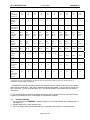
Scaling
Range
checking –
Standard?
Trending –
Standard?
Graphing –
Standard?
Editable
Graphics –
Standard?
Animated
Bitmaps –
Standard?
Alarm and
Status pages
Standard?
Numeric
keys –
Standard?
No. of
System keys
No. of
Function
keys *
LED's
Touch
Screen
SmartStack
option –
Standard?
Battery
Back Ram +
Real Time
Clock –
Standard?
Comprehen
-sive Maths
Facilities
(lines)
Day & Time
Scheduling,
Background
Task –
Standard?
Internal
Registers
(%R)
Operating
Temperature
C°
Storage
Temperature
C°
14 June 2006
MAN0356-04
9
9
9
9
9
9
9
9
9
9
X
9
9
9
9
9
9
9
9
9
X
9
9
9
9
9
9
9
9
9
X
X
X
9
9
9
9
9
9
9
X
X
X
9
9
9
9
9
9
9
9
9
9
9
9
9
9
9
9
9
9
X
9
9
9
9
X
9
9
9
4
4
4
4
6
6
1
1
1
1
10
No
12
18
14
18
5
7
7
7
X
X
X
10
12
12
X
X
X
X
X
X
X
X
X
9
(26X)
9
9
9
9
X
X
X
9
9
9
9
9
9
9
O
O
O
9
9
9
O
9
9
9
X
1024
1024
1024
1024
1024
1024
1024
1024
1024
X
9
9
9
9
9
9
9
9
9
X
240
240
1200
1200
1200
2400
2400
2400
2400
0 - 50
0 - 50
0 - 50
0 - 50
0 - 50
0 - 50
0 - 50
0 - 50
0 - 50
0 - 50
-10
to
+70
-10
to
+70
-10
to
+70
-10
to
+70
-10
to
+60
-10
to
+60
-10
to
+60
-10
to
+60
-10
to
+60
-10
to
+60
Page 11 of 70
CH.1: INTRODUCTION
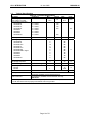
Humidity
Non
Condensing
Storage (%)
Environ
-mental
NEMA4 /
IP65
Y2K
Certified CE
Approved
Size –
Width
X Height
X Depth
(mm)
Cut-out –
Width
X Height
(mm)
Screen
dimensions
(mm)
Input
Voltage
Range
(Vdc)
Weight
(grams)
Network –
DeviceNet
CsCan
Profibus
Data Xfer
from
Automated
device via
network
14 June 2006
MAN0356-04
10
to
90
10
to
90
10
to
90
10
to
90
10
to
85
10
to
85
10
to
85
10
to
85
10
to
85
10
to
85
9
9
9
9
9
9
9
9
9
9
9
9
9
9
9
9
9
9
9
9
180
X 120
X 60
121
X 105
X 38
172
X 105
X 38
281
X 192
X 58
230
X 155
X 70
230
X 155
X 70
182.5
X 138.8
X 57.3
233
X 178
X66.1
303.8
X 231
X 72
326.4
X 259.6
X 72
151
X 89
100
X 85
153
X 85
242
X 158
204
X 131
204
X 131
174
X 131
220.5
X 165.5
289
X 216.2
313
X 246.2
80
X 17
70
X 38
70
X 38
130
X 75
70
X 38
130
X 75
115
X 86
169
X 127
209
X 158
248
X 188
9 – 35
9 – 35
9 – 35
9 – 35
9 – 35
9 - 35
22.6
26.4
22.6
26.4
22.6
26.4
22.6
26.4
325
370
450
1855
~550
~700
800
1500
2400
2700
X
O
O
O
O
O
O
O
O
O
X
O
O
O
O
O
O
O
O
O
* System keys can be programmed to be function keys at specific times in the project. See Function keys in
CBREEZE Software Manual MAN0023
** The HE500TIU100/110 is available with two non-standard features: 20mA current loop communication
and a real-time clock (RTC). Both can be ordered at the time of purchase. The current loop can be re-fit
by the user later. The RTC requires factor re-fit. The HE500TIU050 is only available with the real-time
clock option.
*** The HE500TIU20X provides for the display of both text and full graphics and has a Numeric/Function
Keypad. It also allows the use of a wide range of SmartStack I/O options.
1.2
Equipment Needed
1. The current version of CBREEZE™ software install on a PC running Windows 95™, Windows 98™ or
Windows NT®.
2. HE500TIU050/10X/11X/20X Interface Unit.
3. PC to TIU Programming Cable HE693CBL232 or equivalent See Chapter on Communications
Page 12 of 70
CH.1: INTRODUCTION
14 June 2006
Page 13 of 70
MAN0356-04
CH.1: INTRODUCTION
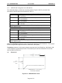
1.3
14 June 2006
MAN0356-04
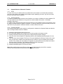
Technical Specifications
Table 1.2 – Technical Specifications
Parameter
Input voltage (VI) Not Tiu3XX
Input voltage (VI) Tiu3XX
Typical power consumption
HE500TIU050
HE500TIU10X
HE500TIU11X
HE500TIU20X
HENX22X
HENX25X
HENX26X
HE500TIU3XX
Inrush input current
Operating temperature
HE500TIU050
HE500TIU10X
HE500TIU10X-6
HE500TIU11X
HE500TIU11X-6
HE500TIU20XA
HE500TIU20XB or higher
HENX22X
HENX25X
HENX26X
HE500TIU3XX
Storage Temperature
NX Storage Temperature
Relative Humidity
Cable Lengths †
RS-232
RS-485
Conditions
Min.
10
22.6
Typical
24
VI = 24VDC
VI = 24VDC
VI = 24VDC
VI = 24VDC
VI = 24VDC
VI = 24VDC
VI = 24VDC
VI = 24VDC
130
130
130
350
VI = 24VDC for 4ms
260
Max.
32
26.4
Units
VDC
mA
400
(non-condensing)
mA
0
0
-10
0
-10
0
0
0
0
0
0
50
50
60
50
60
45
50
70
70
70
50
-20
0
10
70
80
90
1
15
1500
IP rating
°C
°C
%
m
NEMA 4-12/IP65
EN 55 022, Radiated and Conducted Emissions
EN 61000-4-3, Radiated and Conducted RF Immunity
EMC Conformance
ENV 50144
†
Cables beyond the maximum recommended length may create communication problems. Both ends of
an RS-485 network must be properly terminated at 120Ω and grounded.
Page 14 of 70
CH.1: INTRODUCTION
1.4
14 June 2006
MAN0356-04
Upgrade Revision Software & Firmware
1.4.1 Scope
To make use of any new features that are included in this new release on units that were purchased
previous to this release, both software and firmware require updating by the user. Any new unit will be
set-up for the latest version released.
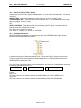
1.4.2 Software Upgrade
To update the software requires that the user install the new version of software from the installation CD.
You may install the new software over any previous version installed. See section 1.4 Software
Installation Instructions.
To update existing projects simple open the project from the newly installed version of the software. Once
the project is saved to disk the update is complete. For backup reasons we recommend that you save the
new version of your project in a different location or under a different file name.
1.4.3 Firmware Upgrade
The following steps assume that a project or configuration is loaded to the Operator Station and that the
user is running the latest version of software.
a)
b)
c)
d)
Upload the project/configuration from the unit.
If a customised character set is loaded to the unit then upload the character set also.
Choose Automation Device from main menu Configure/Communication Settings.
From File menu choose Update TIU Operating System. (See Updating Operating System for more
details).
e) From File menu choose Update TIU Protocol. If you are updating from firmware version 2.00 or later
then you just have to update to the latest protocol file. However if you are updating from firmware
version 1.24 or earlier you most update to a Upgrade.1xx protocol file first, then update to the latest
firmware revision. See Note. (See updating protocol for further information).
f) Choose Download Character Sets to TIU from File menu.
g) Choose Download Project to TIU from File menu.
Note: When updating the protocol file the screen may go blank after the protocol file is complete.
Continue with the procedure as described and the display will recover.
Page 15 of 70
CH.2: HE500TIU050
14 June 2006
MAN0356-04
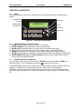
CHAPTER 2: HE500TIU050
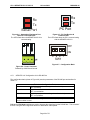
2.1
Scope
The HE500TIU050 is a 2 line text only display terminal. The hardware description is detailed in this
chapter.
Alphanumeric
Keypad
PAUSE Key
HE500TIU050
Programmable
Function Keys
UP Key
DOWN Key
1QZ_
2 ABC
3 DEF
4 GHI
5 JKL
F1
F2
F3
F4
F5
6 MNO
7 PRS
8 TUV
9 WXY
0
F6
F7
F8
F9
F10
+
-
ENTER Key
Figure 2.1 – Front View of HE500TIU050
2.2
a)
b)
c)
d)
e)
f)
g)
HE500TIU050 Button Selection Actions
PAUSE key selects data for editing OR exits from data editing.
PAUSE & DOWN keys pressed together, enters sub menu pages.
PAUSE & UP keys pressed together, exits sub menus to the parent menu pages.
UP key selects the previous menu page, sub menu page, alarms, and increments data
DOWN key selects the next menu page, sub menu page, alarms and also decrements data.
ENTER key sends data to the automation equipment, accepts alarms, and displays accepted alarms.
ALPHANUMERIC KEYPAD and FUNCTION KEYS can be used to enter data or can be used to
preform some pre-programmed action.
2.3
HE500TIU050 Contrast Adjustment
On menu page 1 (after the start-up screen), hold the ENTER key and press the UP or DOWN key to
adjust the contrast. The contrast setting is stored and not lost after removing power.
CONTRAST BAND - allows the user to set the lower and upper limits of contrast. Adjust the lower limit
using the UP or DOWN key and press Enter when done. Do the same for the upper limit.
WARNING: - Changes to the lower or upper limits may allow the user to set the contrast to a setting
where the display may appear blank. It is recommended that the factory setting are used (Min 8A, Max
FE).
Page 16 of 70
CH.2: HE500TIU050
2.4
14 June 2006
MAN0356-04
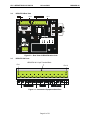
HE500TIU050 Ports
Pin 1
HE500TIU050 8-pin Terminal Block
Pin 8
Figure 2.2 – Automation Equipment Serial Port
2.4.1
HE500TIU050 Configuration of the RS-485 Port
OFF
ON
SW1
Figure 2.3 – Power Connector
Powered by +24VDC and Ground.
Figure 2.4 – Configuration Bank
The configuration bank (shown in Figure 2.5) sets the parameters of the RS-485 port as described in
Table 2.1.
Table 2.1 – Configuration Bank
ON: Pull-up (must be used together with switch 3)
OFF: no Pull-up
Switch 2
ON: 120Ω termination
OFF: no termination
Switch 3
ON: Pull-down (must be used together with switch 1)
OFF: no Pull-down
Switch 4
Reserved for future use
NOTE: Switch 1 and 3 must be used together. Either both pull-up and pull-down are
used or neither is used.
Switch 1
Page 17 of 70
CH.2: HE500TIU050
14 June 2006
MAN0356-04
Pull-up and Pull-down switches are used to increase the signal level on the RS-485 bus. This is useful if
there is a long bus and a significant amount of attenuation is anticipated.
Termination resistance of 120Ω must be placed across each end of the RS-485 bus. With switch 2 ON,
a 120Ω resistance is placed across the bus. This is only used if the HE500TIU050/100/110 is the last
device at either end of the bus.
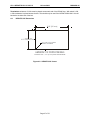
2.5
HE500TIU050 Dimensions
5.95” [151mm]
+0.02
+0.5
3.27”-0.00 [83-0.0 mm]
UP TO 0.04”[1mm] CORNER
RADIUS IS ACCEPTABLE
HE500TIU050 CUTOUT DETAILS
TOLERANCES ARE +/- 0.01” [0.3mm] UNLESS STATED OTHERWISE
Figure 2.5 – HE500TIU050 Cutout
Page 18 of 70
CH.2: HE500TIU050
14 June 2006
NOTES
Page 19 of 70
MAN0356-04
CH. 3: HE500TIU100/101/102/103
14 June 2006
MAN0356-04
CHAPTER 3: HE500TIU100/101/102/103
3.1
Scope
The HE500TIU10X 128 x 64 pixel display, which allows for some graphics and various fonts to be
displayed. The hardware description is detailed in this chapter.
PAUSE Key
ENTER Key
UP Key
DOWN Key
Figure 3.1 - Front View of HE500TIU100
3.2
a)
b)
c)
d)
e)
f)
HE500TIU10X Button Selection Actions
PAUSE key selects data for editing OR exits from data editing.
PAUSE & DOWN keys pressed together, enters sub menu pages.
PAUSE & UP keys pressed together, exits sub menus to the parent menu pages.
UP key selects the previous menu page, sub menu page, alarms, and increments data
DOWN key selects the next menu page, sub menu page, alarms and also decrements data.
ENTER key sends data to the automation equipment, accepts alarms, and displays accepted alarms.
3.3
HE500TIU10X Contrast Adjustment
On menu page 1 (after the start-up screen), hold the ENTER key and press the UP or DOWN key to
adjust the contrast. The contrast setting is stored and not lost after removing power.
CONTRAST BAND - allows the user to set the lower and upper limits of contrast. Adjust the lower limit
using the UP or DOWN key and press Enter when done. Do the same for the upper limit.
WARNING: - Changes to the lower or upper limits may allow the user to set the contrast to a setting
where the display may appear blank. It is recommended that the factory settings are used (Min 8A, Max
FE).
Page 20 of 70
CH. 3: HE500TIU100/101/102/103
3.4
14 June 2006
MAN0356-04
HE500TIUX Rear View
Pin 1
Pin 1
To PC
Rx Pin 2
Tx Pin 3
0V Pin 5
Figure 3.2 – Rear View of HE500TIU100/101/102
3.5
HE500TIU100 Ports
HE500TIU100 13-pin Terminal Block
Pin 1
Pin 13
Figure 3.3 – Automation Equipment Serial Port
Page 21 of 70
CH. 3: HE500TIU100/101/102/103
14 June 2006
MAN0356-04
Rx
Rx
Tx
Tx
PC Port
Serial Port
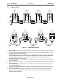
Figure 3.4 – Automation
Equipment Port Receive &
Transmit LEDs
The LED’s flash when the
HE500TIU100/110 is
communicating.
Figure 3.5 – PC Port Receive &
Transmit LEDs
The LED’s flash when the PC is
communicating with the
HE500TIU100/110
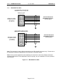
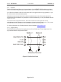
3.5.1 HE500TIU10X Configuration of the RS-485 Port
The configuration bank (shown in Figure 3.8) sets the parameters of the RS-485 port as described in
Table 3.1.
Table 3.1 – Configuration Bank
ON: Pull-up (must be used together with switch 3)
OFF: no Pull-up
Switch 2
ON: 120Ω termination
OFF: no termination
Switch 3
ON: Pull-down (must be used together with switch 1)
OFF: no Pull-down
Switch 4
Reserved for future use
NOTE: Switch 1 and 3 must be used together. Either both pull-up and pull-down are
used or neither is used.
Switch 1
Pull-up and Pull-down switches are used to increase the signal level on the RS-485 bus. This is useful if
there is a long bus and a significant amount of attenuation is anticipated.
Page 22 of 70
CH. 3: HE500TIU100/101/102/103
14 June 2006
MAN0356-04
OFF
ON
SW1
Figure 3.6 – Power Connector
Powered by +24VDC and Ground.
Figure 3.7 – Configuration Bank
Termination resistance of 120Ω must be placed across each end of the RS-485 bus. With switch 2 ON,
a 120Ω resistance is placed across the bus. This should only be used if the HE500TIU050/100/110 is the
last device at either end of the bus.
3.6
HE500TIU10X Dimensions
+0.02
+0.5
3.94”-0.00 [100-0.0 mm]
+0.02
+0.5
3.27”-0.00 [83-0.0 mm]
UP TO 0.04”[1mm] CORNER
RADIUS IS ACCEPTABLE
HE500TIU10X CUTOUT DETAILS
TOLERANCES ARE +/- 0.01” [0.3mm] UNLESS STATED OTHERWISE
Figure 3.8 – HE500TIU10X Cutout
Page 23 of 70
CH. 4: HE500TIU110/111/112/113
14 June 2006
MAN0356-04
CHAPTER 4: HE500TIU110/111/112/113
4.1
Scope
The HE500TIU11X 128 x 64 pixel display, which allows for some graphics and various fonts to be
displayed. The hardware description is detailed in this chapter.
QZ_
ABC
DEF
1
2
3
GHI
JKL
MNO
4
5
6
PRS
TUV
WXY
7
8
9
Numeric
Keypad
Programmable
Function Keys
.
Del
+/-
Figure 4.1 – Front View of HE500TIU110
4.2
a)
b)
c)
d)
e)
f)
g)
HE500TIU11X Button Selection Actions
PAUSE key selects data for editing OR exits from data editing.
PAUSE & DOWN keys pressed together, enters sub menu pages.
PAUSE & UP keys pressed together, exits sub menus to the parent menu pages.
UP key selects the previous menu page, sub menu page, alarms, and increments data
DOWN key selects the next menu page, sub menu page, alarms and also decrements data.
ENTER key sends data to the automation equipment, accepts alarms, and displays accepted alarms.
ALPHANUMERIC KEYPAD and PROGRAMMABLE KEYS can be used to enter data or can be
used to preform some pre-programmed action.
4.3
HE500TIU11X Contrast Adjustment
On menu page 1 (after the start-up screen), hold the ENTER key and press the UP or DOWN key to
adjust the contrast. The contrast setting is stored and not lost after removing power.
CONTRAST BAND - allows the user to set the lower and upper limits of contrast. Adjust the lower limit
using the UP or DOWN key and press Enter when done. Do the same for the upper limit.
WARNING: - Changes to the lower or upper limits may allow the user to set the contrast to a setting
where the display may appear blank. It is recommended that the factory setting are used (Min 8A, Max
FE).
Page 24 of 70
CH. 4: HE500TIU110/111/112/113
4.4
14 June 2006
MAN0356-04
HE500TIU11X Rear View
Pin 1
Pin 1
To PC
Rx Pin 2
Tx Pin 3
0V Pin 5
Figure 4.2 – Rear View of HE500TIU110/111/112
4.5
HE500TIU110 Ports
HE500TIU110 13-pin Terminal Block
Pin 1
Pin 13
Figure 4.3 – Automation Equipment Serial Port
Page 25 of 70
CH. 4: HE500TIU110/111/112/113
14 June 2006
MAN0356-04
Rx
Rx
Tx
Tx
PC Port
Serial Port
Figure 4.4 – Automation Equipment Port
Receive & Transmit LEDs
The LED’s flash when the HE500TIU100/110 is
communicating.
Figure 4.5 – PC Port Receive &
Transmit LEDs
The LED’s flash when the PC is communicating
with the HE500TIU100/110
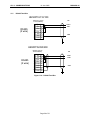
OFF
ON
SW1
Figure 4.7 – Configuration Bank
Figure 4.6 – Power Connector
Powered by +24VDC and Ground.
4.5.1
HE500TIU11X Configuration of the RS-485 Port
The configuration bank (shown in Figure 4.8) sets the parameters of the RS-485 port as described in
Table 4.1.
Table 4.1 – Configuration Bank
ON: Pull-up (must be used together with switch 3)
OFF: no Pull-up
Switch 2
ON: 120Ω termination
OFF: no termination
Switch 3
ON: Pull-down (must be used together with switch 1)
OFF: no Pull-down
Switch 4
Reserved for future use
NOTE: Switch 1 and 3 must be used together. Either both pull-up and pull-down are
used or neither is used.
Switch 1
Pull-up and Pull-down switches are used to increase the signal level on the RS-485 bus. This is useful if
there is a long bus and a significant amount of attenuation is anticipated.
Page 26 of 70
CH. 4: HE500TIU110/111/112/113
14 June 2006
MAN0356-04
Termination resistance of 120Ω must be placed across each end of the RS-485 bus. With switch 2 ON,
a 120Ω resistance is placed across the bus. This should only be used if the HE500TIU050/100/110 is the
last device at either end of the bus.
4.6
HE500TIU11X Dimensions
5.95” [151mm]
+0.02
+0.5
3.27”-0.00 [83-0.0 mm]
UP TO 0.04”[1mm] CORNER
RADIUS IS ACCEPTABLE
HE500TIU11X CUTOUT DETAILS
TOLERANCES ARE +/- 0.01” [0.3mm] UNLESS STATED OTHERWISE
Figure 4.8 – HE500TIU11X Cutout
Page 27 of 70
CH. 5: HE500TIU200/201/202/203
14 June 2006
MAN0356-04
CHAPTER 5: HE500TIU200/201/202/203
5.1
Scope
The HE500TIU20X is 240 x 128 pixel display which allows for full graphic screen. The hardware
description is cover under the following chapter
QZ
ABC
DEF
1
2
3
GHI
JKL
MNO
4
5
6
PRS
TUV
WXY
7
8
9
.
0
SPACE
Del
0
+/NEXT
F9
F10
F11
F12
F13
F14
F15
F16
F17
F18
Figure 5.1 – Front View of HE500TIU20X
5.2
a)
b)
c)
d)
e)
f)
g)
h)
HE500TIU20X Button Selection Actions
PAUSE key selects data for editing OR exits from data editing.
PAUSE & DOWN keys pressed together, enters sub menu pages.
PAUSE & UP keys pressed together, exits sub menus to the parent menu pages.
UP key selects the previous menu page, sub menu page, alarms, and increments data
DOWN key selects the next menu page, sub menu page, alarms and also decrements data.
ENTER key sends data to the automation equipment, accepts alarms, and displays accepted alarms.
ALPHANUMERIC KEYPAD can be used to enter data
PROGRAMMABLE KEYS can be used to preform some pre-programmed action.
Page 28 of 70
CH. 5: HE500TIU200/201/202/203
14 June 2006
MAN0356-04
5.3
HE500TIU20X Contrast Adjustment
On menu page 1 (after the start-up screen), hold the ENTER key and press the UP or DOWN key to
adjust the contrast. The contrast setting is stored and not lost after removing power.
CONTRAST BAND - allows the user to set the lower and upper limits of contrast. Adjust the lower limit
using the UP or DOWN key and press Enter when done. Do the same for the upper limit.
WARNING: - Changes to the lower or upper limits may allow the user to set the contrast to a setting
where the display may appear blank. It is recommended that the factory setting are used (Min 8A, Max
FE).
5.4
HE500TIU20X Rear View
Serial No:
Model No:
Figure 5.2 – Rear View of HE500TIU200/201/202
5.5
HE500TIU20X Ports
Pin 1
HE500TIU20X 8-pin Terminal Block
Figure 5.3 Automated Equipment Serial Port
Page 29 of 70
Pin 8
CH. 5: HE500TIU200/201/202/203
14 June 2006
MAN0356-04
Rx
Rx
Tx
Tx
PC Port
Serial Port
Figure 5.5 – PC Port Receive &
Transmit LEDs
The LED’s flash when the PC is
communicating with the
HE500TIU100/110
Figure 5.4 – Automation
Equipment Port Receive &
Transmit LEDs
The LED’s flash when the
HE500TIU100/110 is
communicating.
OFF
ON
SW1
Figure 5.7 – Configuration Bank
Figure 5.6 – Power Connector
Powered by +24VDC and Ground.
Page 30 of 70
CH. 5: HE500TIU200/201/202/203
6.5.1
14 June 2006
MAN0356-04
HE500TIU20X Configuration of the RS-485 Port
The configuration bank (shown in Figure 2.23) sets the parameters of the RS-485 port as described in
Table 5.1.
Table 5.1 – Configuration Bank
ON: Pull-up (must be used together with switch 3)
OFF: no Pull-up
Switch 2
ON: 120Ω termination
OFF: no termination
Switch 3
ON: Pull-down (must be used together with switch 1)
OFF: no Pull-down
Switch 4
Reserved for future use
NOTE: Switch 1 and 3 must be used together. Either both pull-up and pull-down are
used or neither is used.
Switch 1
Pull-up and Pull-down switches are used to increase the signal level on the RS-485 bus. This is useful if
there is a long bus and a significant amount of attenuation is anticipated.
Termination resistance of 120Ω must be placed across each end of the RS-485 bus. With switch 2 ON,
a 120Ω resistance is placed across the bus. This should only be used if the HE500TIU050/10X/11X/20X
is the last device at either end of the bus.
5.6
HE500TIU20X Dimensions
+0.02
9.72”
-0.00
6.2”
+0.02
-0.00
+0.5
[247 mm]
-0.0
+0.5
[157mm]
-0.0
UP TO 0.04” Corner Radius Is Acceptable [1mm]
TOLERANCES ARE +/- 0.01” [0.3mm] UNLESS
STATED OTHERWISE
Figure 5.8 – HE500TIU20X Cutout
Page 31 of 70
CH. 6: HENX2XXTXXX
14 June 2006
MAN0356-04
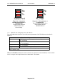
CHAPTER 6: HENX2XXTXXX
6.1
Scope
The HENX2XXTXXX can be either a 128 x 64 (NX22X) or a 240 x 128 (NX25X) pixel display which both
allow for full graphic screen. The hardware description is covered under the following chapter.
Figure 6.1 – HENX22XTXXX
Figure 6.2 – HENX25XTXXX
Page 32 of 70
CH. 6: HENX2XXTXXX
6.2
a)
b)
c)
d)
e)
f)
g)
h)
i)
6.3
14 June 2006
MAN0356-04
Button Selection Actions
LEFT & RIGHT keys select data for editing OR exits from data editing.
PAUSE & DOWN keys pressed together, enters sub menu pages.
PAUSE & UP keys pressed together, exits sub menus to the parent menu pages.
UP key selects the previous menu page, sub menu page, alarms, and increments data
DOWN key selects the next menu page, sub menu page, alarms and also decrements data.
ENTER key sends data to the automation equipment, accepts alarms, and displays accepted alarms.
ALPHANUMERIC KEYPAD can be used to enter data
PROGRAMMABLE KEYS can be used to preform some pre-programmed action.
ESC key is used to return to main menu
Contrast Adjustment
On menu page 1 (after the start-up screen), hold the ENTER key and press the UP or DOWN key to
adjust the contrast. The contrast setting is stored and not lost after removing power.
CONTRAST BAND - allows the user to set the lower and upper limits of contrast. Adjust the lower limit
using the UP or DOWN key and press Enter when done. Do the same for the upper limit.
WARNING: - Changes to the lower or upper limits may allow the user to set the contrast to a setting
where the display may appear blank. It is recommended that the factory setting are used (Min 8A, Max
FE).
6.4
Rear View
Figure 6.3 – Rear View of HENX2XXTXXX
Page 33 of 70
CH. 6: HENX2XXTXXX
6.5
14 June 2006
MAN0356-04
Ports
Figure 6.4 Automated Equipment Serial Port (MJ1)
+5V
TX 485/422+
TX 485/422RX 485/422+
RX 485/422TX RS232
0V (GND)
RX RS232
Frame Gnd
10
10
5
5
IN1
IN2
OUT1
OUT2
EXT 0V
IN1
IN1
OUT1
OUT2
EXT 24V
9
1
2
3
4
5
6
7
8
Figure 6.5 - Automated Equipment
Serial Port (CN1)
1
1
2
3
4
5
6
7
8
9
10
Figure 6.6 – Pulse I/O Port
5
6
9
Figure 6.7 – PC Port 9-way D-type Sub (Female)
Page 34 of 70
Figure 6.8 – Power Connector
Powered by +24V and Ground (0V)
CH. 6: HENX2XXTXXX
14 June 2006
MAN0356-04
HENX2XXTXXX 5-pin Terminal Block
V+
CN_H
SHIELD
Pin 5
CN_L
V-
Pin 1
Figure 6.9 – CSCAN Network Port (NET1)
Rx
Rx
Tx
Tx
PC Port
Serial Port
Figure 6.10 – Automation
Equipment Port Receive &
Transmit LEDs
The LED’s flash when the
HENX2XXTXXX
is communicating.
Figure 6.11 – PC Port Receive &
Transmit LEDs
The LED’s flash when the PC is
communicating with the
HENX2XXTXXX
OFF
OFF
ON
ON
SW 1
Figure 6.12 – Configuration Bank 1
SW 2
Figure 6.13 – Configuration Bank 2
Page 35 of 70
CH. 6: HENX2XXTXXX
6.5.1
14 June 2006
MAN0356-04
HE500TIU20X Configuration of the RS-485 Port
The configuration banks, for both sets of switches (shown in Figure 6.9 & 6.10), set each of the
parameters of both RS-485 ports as described in Table 6.1:
Table 6.1 – Configuration Bank for SW1
ON: Pull-up (must be used together with switch 3)
OFF: no Pull-up
Switch 2
ON: 120Ω termination on the Receive pins
OFF: no termination
Switch 3
ON: Pull-down (must be used together with switch 1)
OFF: no Pull-down
Switch 4
ON: Shorts Rx+ with Tx+
OFF: No Short
NOTE: Switch 1 and 3 must be used together. Either both pull-up and pull-down are
used or neither is used.
Switch 1
Table 6.2 – Configuration Bank for SW2
ON: Pull-up (must be used together with switch 3)
OFF: no Pull-up
Switch 2
ON: 120Ω termination on the Receive Pins
OFF: no termination
Switch 3
ON: Pull-down (must be used together with switch 1)
OFF: no Pull-down
Switch 4
ON: Shorts Rx- with Tx- of Port 1
OFF: No Short
NOTE: Switch 1 and 3 must be used together. Either both pull-up and pull-down are
used or neither is used.
Switch 1
Pull-up and Pull-down switches are used to increase the signal level on the RS-485 bus. This is useful if
there is a long bus and a significant amount of attenuation is anticipated.
Termination resistance of 120Ω must be placed across each end of the RS-485 bus. With Switch 2 ON,
a 120Ω resistance is placed across the bus. This should only be used if the HENX2XXTXX is the last
device at either end of the bus.
6.6
Dimensions
+0.02
8.06”
-0.00
+0.02
5.17”
-0.00
+0.5
[204 mm]
-0.0
+0.5
[131mm]
-0.0
UP TO 0.04” Corner Radius Is Acceptable [1mm]
TOLERANCES ARE +/- 0.01” [0.3mm]
UNLESS STATED OTHERWISE
Figure 6.14 – HENX2XXT2XX Cutout
Page 36 of 70
CH. 7: HE500TIU3XX
14 June 2006
MAN0356-04
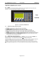
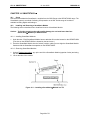
CHAPTER 7: HE500TIU300/301/302/303/310/311/312/313/320/321/322/323
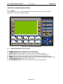
7.1
Scope
The HE500TIU3XX has a 320 x 240 pixel display which allows for full graphic screen. The screen
technology is indicated by the part number as follows…
HE500TIU30X 16 Grey scale screen
HE500TIU31X 16 Colour STN screen
HE500TIU32X 16 Colour TFT screen
The hardware description is covered under the following chapter
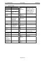
Figure 7.1 – Front View of HE500TIU3XX
7.2
HE500TIU3XX Touch Key Pad
The Tiu3XX has a touch keypad that can be assigned to perform a variety of key macro operations from
within the CBreeze configuration package.
7.3
HE500TIU3XX Contrast Adjustment
On menu page 1 (after the start-up screen), hold the SYSTEM key and press the F1 or F2 key to adjust
the contrast. The contrast setting is stored and not lost after removing power. (Note TIU32X series
feature a TFT display which do not require contrast adjustment)
Page 37 of 70
5
CH. 7: HE500TIU3XX
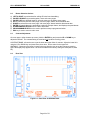
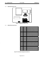
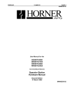
7.4
14 June 2006
MAN0356-04
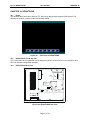
HE500TIU3XX Rear View
MJ2
MJ1
CN1
CN2
Figure 7.2 HE500TIU3XX Rear View
7.5
HE500TIU3XX Serial Ports
Pin No
1
2
3
4
5
6
7
8
9
10
11
12
13
14
15
16
17
18
19
20
21
22
23
24
25
Signal
FG
TXD
RXD
RTS
CTS
SG
+5V
0V
+SD
-SD
+RTS
-RTS
-CTS
+CTS
+RD
-RD
Function
Frame Ground
RS-232-C Send Data
RS-232-C Receive Data
RS-232-C Request To Send
RS-232-C Clear To Send
Not Connected
Signal Ground
Not Connected
Internal Use Only Do Not Use!
Internal Use Only Do Not Use!
Not Connected
RS-422/RS-485 Send Data (+)
RS-422/RS-485 Send Data (-)
RS-422 Request To Send (+)
Not Connected
Not Connected
RS-422 Request To Send (-)
RS-422 Clear To Send (-)
RS-422 Clear To Send (+)
Not Connected
Not Connected
Not Connected
Not Connected
RS-422/RS-485 Receive Data (+)
RS-422/RS-485 Receive Data (-)
Figure 7.3 Automation Equipment Serial Port
Page 38 of 70
CH. 7: HE500TIU3XX
14 June 2006
MAN0356-04
+
24VDC
-
Figure 7.4 – Power Connector
Powered by +24VDC and Ground
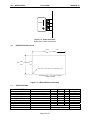
7.6
HE500TIU3XX Dimensions
+0.02
6.85”
-0.00
5.2”
+0.02
+0.5
[174 mm]
-0.0
+0.5
[131mm]
-0.00
-0.0
UP TO 0.04” Corner Radius Is Acceptable [1mm]
TOLERANCES ARE +/- 0.01” [0.3mm] UNLESS
STATED OTHERWISE
Figure 7.5 – HE500TIU3XX Cutout Details
7.7
SPECIFICATIONS
PARAMETER
Input Voltage (Vi)
Typical Power Consumption
Inrush Input Current
Withstand Voltage
Operating Temperature
Storage Temperature
Relative Humidity
Weight
Dimensions
Panel Cut-out
Conditions
Min
21.6
Vi = 24VDC
Vi = 24VDC for 1mS
DC Terminals to Earth
non-Condensing
WxHxD
WxH
Page 39 of 70
0
-10
5
Typical
24
Max
26.4
10
17
500
50
60
85
0.8
182.5 x 138.8 x 57.3
174 (+0.5) x 131 (+0.5)
Units
VDC
WATTS
A
VAC for 1 Min
°C
°C
%
Kg
mm
mm
CH. 7: HE500TIU3XX
14 June 2006
NOTES
Page 40 of 70
MAN0356-04
CH. 8: HE500TIU4XX
14 June 2006
MAN0356-04
CHAPTER 8: HE500TIU4XX
8.1
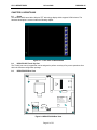
Scope
The HE500TIU4XX has a 800 x 600 pixel TFT technology display which supports 32768 colours. The
hardware description is covered under the following chapter
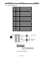
Figure 8.1 – Front View of HE500TIU4XX
8.2
HE500TIU4XX Touch Key Pad
The Tiu4XX has a touch keypad that can be assigned to perform a variety of key macro operations from
within the CBreeze configuration package.
HE500TIU4XX Rear View
CN6
CN5
MEMORY
TYPE :HE500TIU4XX
Ser No. :0120899A
INPUT :24VDC
CURRENT:0.92A
HORNER IRELAND LTD
ASSEMBLED IN IRELAND
24VDC
+
-
8.3
PRINTER
MJ1
CN1
MJ2
Figure 8.2 HE500TIU4XX Rear View
Page 41 of 70
CF
5
CH. 8: HE500TIU4XX
8.4
14 June 2006
MAN0356-04
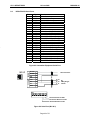
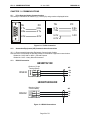
HE500TIU4XX Serial Ports
Pin No
1
2
3
4
5
6
7
8
9
10
11
12
13
14
15
16
17
18
19
20
21
22
23
24
25
Signal
FG
TXD
RXD
RTS
CTS
SG
+5V
0V
+SD
-SD
+RTS
-RTS
-CTS
+CTS
+RD
-RD
Function
Frame Ground
RS-232-C Send Data
RS-232-C Receive Data
RS-232-C Request To Send
RS-232-C Clear To Send
Not Connected
Signal Ground
Not Connected
Internal Use Only Do Not Use!
Internal Use Only Do Not Use!
Not Connected
RS-422/RS-485 Send Data (+)
RS-422/RS-485 Send Data (-)
RS-422 Request To Send (+)
Not Connected
Not Connected
RS-422 Request To Send (-)
RS-422 Clear To Send (-)
RS-422 Clear To Send (+)
Not Connected
Not Connected
Not Connected
Not Connected
RS-422/RS-485 Receive Data (+)
RS-422/RS-485 Receive Data (-)
Figure 8.3 Automation Equipment Serial Port
RS485
Rx/TxD+ 1
2
AE Connections
Rx/TxD+5V
+5V
RS232
TxD
0V
0V
RxD
3
4
8
5
6
7
2
Rx
5 0V
3
Tx
PC
9-Way D-Type
Female
ON
1 2 3 4 5 6 7 8
Terminal Resistor for MJ2
Rx Terminal Resistor for CN1
Terminal Resistor for MJ1
Figure 8.4 Serial Port (MJ1 & 2)
Page 42 of 70
CH. 8: HE500TIU4XX
14 June 2006
MAN0356-04
+
24VDC
-
Figure 8.4 – TIU4XX Power Connector
Powered by +24VDC and Ground
8.5
HE500TIU4XX Dimensions
+0.02
8.68”
-0.00
+0.02
6.52”
-0.00
+0.5
[220.5 mm]
-0.0
+0.5
[165.5mm]
-0.0
UP TO 0.04” Corner Radius Is Acceptable [1mm]
TOLERANCES ARE +/- 0.01” [0.3mm] UNLESS
STATED OTHERWISE
Figure 8.5 – HE500TIU4XX Cutout Details
Page 43 of 70
CH. 8: HE500TIU4XX
8.6
SPECIFICATIONS
PARAMETER
CONDITIONS
Display Size
8.4"
Display Type
TFT Colour LCD
Display
800 * 600
Resolution
Colour
32768 colours + 16
Colours in Blink
Mode
Backlight
50,000 Hrs
Average
Lifetime
Backup Memory 64Kbytes SRAM
Clock
RTC Battery
Backed (Sanyo
CR2450-CN1
Lithium Coin)
Backup Period
5 years (ambient
25 °C)
CF Card
Compatible with
Interface
Compact Flash™
Printer Interface Centronics
Compatible half
pitch 20 pins
Nominal Input
24VDC
Voltage
Input Voltage
24VDC ± 10%
Range
Inrush Current
Power
Requirement
Permissable
Power Failure
Voltage
Tolerance
(between DC
Terminal and
Field Ground)
Insulation
Resistance
14 June 2006
PARAMETER
Serial Ports
RS232
RS422/485
Operating
Ambient
Temperature
MAN0356-04
UNITS
Asynchronous Type
Data Length: 7, 8 bits
Parity: Even, Odd, None
Stop Bits: 1, 2 bits
Baud Rate: 4800, 9600,
19200, 38400, 57600,
76800, 115200 bps
0-50 °C
Storage
Temperature
-10 - +60 °C
Humidity
85%RH, (non-Condensing)
Weight
Approx 1.5 Kg
Dimensions
(W*H*D) mm
233 * 178 * 66.1
Panel Cut-Out
mm
Seal Rating
220.5 (+0.5) * 165.5 (+0.5)
Front Panel- IP65 (When
Waterproof Sheet is used)
Rear Cover- IP20
Natural Convection
CE
25A, 0.7mS
22W or less
Cooling
Approvals
Less than 1mS
Touch Panel
Method
Touch Panel
Resolution
Analogue Resistive
Membrane
1024W*1024H
Mechanical
Lifetime
1 million times, or more
500Vac, 1min
500VDC 10MΩ or
more
Page 44 of 70
CH. 8: HE500TIU4XX
14 June 2006
NOTES
Page 45 of 70
MAN0356-04
CH. 9: HE500TIU5XX
14 June 2006
MAN0356-04
CHAPTER 9: HE500TIU5XX
9.1
Scope
The HE500TIU5XX has a 800 x 600 pixel TFT technology display which supports 32768 colours. The
hardware description is covered under the following chapter
Figure 9.1 – Front View of HE500TIU5XX
9.2
HE500TIU5XX Touch Key Pad
The Tiu5XX has a touch keypad that can be assigned to perform a variety of key macro operations from
within the CBreeze configuration package.
9.3
HE500TIU5XX Rear View
CN6
CN5
MEMORY
TYPE :HE500TIU5XX
Ser No. :0120899A
INPUT :24VDC
CURRENT: 1.25 A
HORNER IRELAND LTD
ASSEMBLED IN IRELAND
24VDC
+
-
LAN
CN1
CF
MJ1
MJ2
PRINTER
Figure 9.2 HE500TIU5XX Rear View
Page 46 of 70
5
CH. 9: HE500TIU5XX
9.4
14 June 2006
MAN0356-04
HE500TIU5XX Serial Ports
Pin No
1
2
3
4
5
6
7
8
9
10
11
12
13
14
15
16
17
18
19
20
21
22
23
24
25
Signal
FG
TXD
RXD
RTS
CTS
SG
+5V
0V
+SD
-SD
+RTS
-RTS
-CTS
+CTS
+RD
-RD
Function
Frame Ground
RS-232-C Send Data
RS-232-C Receive Data
RS-232-C Request To Send
RS-232-C Clear To Send
Not Connected
Signal Ground
Not Connected
Internal Use Only Do Not Use!
Internal Use Only Do Not Use!
Not Connected
RS-422/RS-485 Send Data (+)
RS-422/RS-485 Send Data (-)
RS-422 Request To Send (+)
Not Connected
Not Connected
RS-422 Request To Send (-)
RS-422 Clear To Send (-)
RS-422 Clear To Send (+)
Not Connected
Not Connected
Not Connected
Not Connected
RS-422/RS-485 Receive Data (+)
RS-422/RS-485 Receive Data (-)
Figure 9.3 Automation Equipment Serial Port
RS485
Rx/TxD+ 1
Rx/TxD- 2
+5V
+5V
RS232
TxD
0V
0V
RxD
AE Connections
3
4
8
5
6
7
2
Rx
5 0V
3
Tx
PC
9-Way D-Type
Female
ON
1 2 3 4 5 6 7 8
Terminal Resistor for MJ2
Rx Terminal Resistor for CN1
Terminal Resistor for MJ1
Figure 9.3 Automation Equipment Serial Port
Page 47 of 70
CH. 9: HE500TIU5XX
14 June 2006
MAN0356-04
+
24VDC
-
Figure 9.4 – TIU5XX Power Connector
Powered by +24VDC and Ground
9.5
HE500TIU5XX Dimensions
+0.02
11.38”
-0.00
+0.02
8.51”
-0.00
+0.5
[289 mm]
-0.0
+0.5
[216.2mm]
-0.0
UP TO 0.04” Corner Radius Is Acceptable [1mm]
TOLERANCES ARE +/- 0.01” [0.3mm] UNLESS
STATED OTHERWISE
Figure 9.5 – HE500TIU5XX Cutout Details
Page 48 of 70
CH. 9: HE500TIU5XX
9.6
SPECIFICATIONS
PARAMETER
CONDITIONS
Display Size
10.41"
Display Type
TFT Colour LCD
Display
800 * 600
Resolution
Colour
32768 colours + 16
Colours in Blink
Mode
Backlight
50,000 Hrs
Average
Lifetime
Backup Memory 64Kbytes SRAM
Clock
RTC Battery
Backed (Sanyo
CR2450-CN1
Lithium Coin)
Backup Period
5 years (ambient
25 °C)
CF Card
Compatible with
Interface
Compact Flash™
Printer Interface Centronics
Compatible half
pitch 20 pins
Nominal Input
24VDC
Voltage
Input Voltage
24VDC ± 10%
Range
Inrush Current
Power
Requirement
Permissable
Power Failure
Voltage
Tolerance
(between DC
Terminal and
Field Ground)
Insulation
Resistance
14 June 2006
PARAMETER
Serial Ports
RS232
RS422/485
Operating
Ambient
Temperature
MAN0356-04
UNITS
Asynchronous Type
Data Length: 7, 8 bits
Parity: Even, Odd, None
Stop Bits: 1, 2 bits
Baud Rate: 4800, 9600,
19200, 38400, 57600,
76800, 115200 bps
0-50 °C
Storage
Temperature
-10 - +60 °C
Humidity
85%RH, (non-Condensing)
Weight
Approx. 2.4Kg
Dimensions
(W*H*D) mm
303.8 * 231 * 72.0
Panel Cut-Out
mm
Seal Rating
289.0 (+0.5) * 216.2 (+0.5)
Front Panel- IP65 (When
Waterproof Sheet is used)
Rear Cover- IP20
Natural Convection
CE
30A, 1mS
30W or less
Cooling
Approvals
Less than 1mS
Touch Panel
Method
Touch Panel
Resolution
Analogue Resistive
Membrane
1024W*1024H
Mechanical
Lifetime
1 million times, or more
500Vac, 1min
500VDC 10MΩ or
more
Page 49 of 70
CH. 9: HE500TIU5XX
14 June 2006
NOTES
Page 50 of 70
MAN0356-04
CH. 10: HE500TIU6XX
14 June 2006
MAN0356-04
CHAPTER 10: HE500TIU6XX
10.1
Scope
The HE500TIU6XX has a 800 x 600 pixel TFT technology display which supports 32768 colours. The
hardware description is covered under the following chapter
Figure 10.1 – Front View of HE500TIU6XX
10.2
HE500TIU6XX Touch Key Pad
The Tiu6XX has a touch keypad that can be assigned to perform a variety of key macro operations from
within the CBreeze configuration package.
10.3
HE500TIU6XX Rear View
CN6
CN5
MEMORY
TYPE :HE500TIU6XX
Ser No. :0120899A
INPUT :24VDC
CURRENT: 1.25 A
HORNER IRELAND LTD
ASSEMBLED IN IRELAND
LAN
CN1
CF
MJ1
MJ2
24VDC
+
-
Figure 10.2 HE500TIU6XX Rear View
Page 51 of 70
PRINTER
5
CH. 10: HE500TIU6XX
10.4
14 June 2006
MAN0356-04
HE500TIU6XX Serial Ports
Pin No
1
2
3
4
5
6
7
8
9
10
11
12
13
14
15
16
17
18
19
20
21
22
23
24
25
Signal
FG
TXD
RXD
RTS
CTS
Function
Frame Ground
RS-232-C Send Data
RS-232-C Receive Data
RS-232-C Request To Send
RS-232-C Clear To Send
Not Connected
Signal Ground
Not Connected
Internal Use Only Do Not Use!
Internal Use Only Do Not Use!
Not Connected
RS-422/RS-485 Send Data (+)
RS-422/RS-485 Send Data (-)
RS-422 Request To Send (+)
Not Connected
Not Connected
RS-422 Request To Send (-)
RS-422 Clear To Send (-)
RS-422 Clear To Send (+)
Not Connected
Not Connected
Not Connected
Not Connected
RS-422/RS-485 Receive Data (+)
RS-422/RS-485 Receive Data (-)
SG
+5V
0V
+SD
-SD
+RTS
-RTS
-CTS
+CTS
+RD
-RD
Figure 10.3 Automation Equipment Serial Port (CN1)
RS485
Rx/TxD+ 1
2
AE Connections
Rx/TxD+5V
+5V
RS232
TxD
0V
0V
RxD
3
4
8
5
6
7
2
Rx
5 0V
3
Tx
PC
9-Way D-Type
Female
ON
1 2 3 4 5 6 7 8
Terminal Resistor for MJ2
Rx Terminal Resistor for CN1
Terminal Resistor for MJ1
Figure 10.4 Serial Ports (MJ1 & 2)
Page 52 of 70
CH. 10: HE500TIU6XX
14 June 2006
MAN0356-04
+
24VDC
-
Figure 10.4 – TIU6XX Power Connector
Powered by +24VDC and Ground
10.5
HE500TIU6XX Dimensions
+0.02
12.32”
-0.00
+0.02
245.92”
-0.00
+0.5
[313 mm]
-0.0
+0.5
[246.2mm]
-0.0
UP TO 0.04” Corner Radius Is Acceptable [1mm]
TOLERANCES ARE +/- 0.01” [0.3mm] UNLESS
STATED OTHERWISE
Figure 10.5 – HE500TIU6XX Cutout Details
Page 53 of 70
CH. 10: HE500TIU6XX
10.6
14 June 2006
MAN0356-04
Specifications
PARAMETER
Display Size
Display Type
Display
Resolution
Colour
Backlight
Average
Lifetime
Backup Memory
Clock
Backup Period
CF Card
Interface
Printer Interface
Nominal Input
Voltage
Input Voltage
Range
Inrush Current
Power
Requirement
Permissable
Power Failure
Voltage
Tolerance
(between DC
Terminal and
Field Ground)
Insulation
Resistance
CONDITIONS
12.1"
TFT Colour LCD
800 * 600
32768 colours + 16
Colours in Blink
Mode
50,000 Hrs
64Kbytes SRAM
RTC Battery
Backed (Sanyo
CR2450-CN1
Lithium Coin)
5 years (ambient
25 °C)
Compatible with
Compact Flash™
Centronics
Compatible half
pitch 20 pins
24VDC
PARAMETER
Serial Ports
RS232
RS422/485
Operating
Ambient
Temperature
UNITS
Asynchronous Type
Data Length: 7, 8 bits
Parity: Even, Odd, None
Stop Bits: 1, 2 bits
Baud Rate: 4800, 9600,
19200, 38400, 57600,
76800, 115200 bps
0-50 °C
Storage
Temperature
-10 - +60 °C
Humidity
85%RH, (non-Condensing)
Weight
Approx. 2.75Kg
Dimensions
(W*H*D) mm
326.4 * 259.6 * 72.0
313 (+0.5) * 246.2 (+0.5)
24VDC ± 10%
Panel Cut-Out
mm
Seal Rating
30A, 1mS
30W or less
Cooling
Approvals
Less than 1mS
Touch Panel
Method
Touch Panel
Resolution
Analogue Resistive
Membrane
1024W*1024H
Mechanical
Lifetime
1 million times, or more
500Vac, 1min
500VDC 10MΩ or
more
Page 54 of 70
Front Panel- IP65 (When
Waterproof Sheet is used)
Rear Cover- IP20
Natural Convection
CE
CH. 10: HE500TIU6XX
14 June 2006
NOTES
Page 55 of 70
MAN0356-04
CH. 11: COMMUNICATIONS
14 June 2006
MAN0356-04
CHAPTER 11: COMMUNICATIONS
11.1
PC to Operator Station Communications
The serial pin connections for transmit (Tx), receive (Rx) and ground are displayed below.
1
5
TIU
PC
2 Tx
3 Rx
2 Rx
3 Tx
5 0V
5 0V
Figure 7.1
– PC Programming Serial
TIU
PC Port &
Connection Detail TIU0XX, 1XX and 2XX
8 Tx
2 Rx
7 Rx
3 Port
Tx &
Figure 7.2
– PC Programming Serial
Connection Detail TIU3XX
5 0V
6 0V
5 0V
Figure 11.1 Tiu/PC Connection
11.2
Automation Equipment (AE) Communications Connections
10.2.1 Recommended Automation Equipment Communication Cables
Horner Electric recommends the following cables for automation equipment communication:
Belden No. 8105, 9807 or 9832 – General Purpose
Belden No. 8165 – Heavy Noise Environment
RS-232 Connection
HE500TIU1XX
RS232
RS232
(Section of 13-pin
Terminal Block)
TxD
GND
RxD
AE
Rx
0V
6
7
8
Tx
HE500TIU050/20X
(Section of 8-pin
Terminal Block)
RS232
RS232
11.3
TxD
GND
RxD
AE
Rx
0V
Tx
5
6
7
Figure 11.2 RS232 Connections
Page 56 of 70
CH. 11: COMMUNICATIONS
11.4
14 June 2006
MAN0356-04
RS-422/485 Four-Wire
HE500TIU110/100
RS422/485
(4 wire)
RS232 RS422/485
(Section of 13-pin
Terminal Block)
Tx+
TxRx+
RxTxD
GND
RxD
2
3
4
5
6
7
8
Automated Equipment
RS422/485 Connections
See Note Below
RS422/485
(4 wire)
RS232 RS422/485
HE500TIU050/200
Tx+
TxRx+
RxTxD
GND
RxD
GND
1
2
3
4
5
6
7
8
Automated Equipment
RS422/485 Connections
See Note Below
Note: The descriptions used by different manufacturers for RS-422/485 connections vary. Please refer to
the automation equipment manufacturers own manuals for connection details.
Note: Horner produces application notes explaining the connection to each of the different automated
equipment manufactures. These application notes are ongoing, see your installation CD for any released
documentation.
Figure 11.3 – RS-422/485 Four-Wire
Page 57 of 70
CH. 11: COMMUNICATIONS
MAN0356-04
RS-485 Two-Wire
HE500TIU110/100
AE
Tx+
TxRx+
RxTxD
GND
RxD
Tx/Rx+
RS232 RS422/485
(Section of 13-pin
Terminal Block)
RS485
(2 wire)
2
3
4
5
6
7
8
Tx/Rx-
COM
HE500TIU050/200
(Section of 8-pin
Terminal Block)
RS485
(2 wire)
RS232 RS422/485
11.5
14 June 2006
Tx+
TxRx+
RxTxD
GND
RxD
GND
1
2
3
4
5
6
7
8
Figure 11.4 – RS-485 Two-Wire
Page 58 of 70
AE
Tx/Rx+
Tx/Rx-
COM
CH. 11: COMMUNICATIONS
11.6
14 June 2006
MAN0356-04
Current Loop
The following diagram shows the connection to a device with an active 20mA current loop. The current
loop on the HE500TIU100/110 is passive. Either the PLC must provide the 20mA source or an external
current source must be supplied.
20mA Loop
20mA Loop
T+
TR+
R-
+
9
10
11
12
ST
SR
-
Figure 11.5 – Current Loop
Note: Current Loop is not a standard option on the HE500TIU100/110. Current loop must be ordered
specifically or can be re-fit into a standard unit. Contact a Horner Electric dealer for more information.
Note: Current Loop is not an option with the HE500TIU050/101/111/20X/3XX/4XX/5XX/6XX
Page 59 of 70
CH. 12: GETTING STARTED
14 June 2006
MAN0356-04
CHAPTER 12: GETTING STARTED
12.1
Self-Test (TIU050, TIU1xx, TIU2xx)
Power up the unit with the UP and ENTER keys pressed at the same time. The unit enters a self-test
mode. The self-test consists of the following four checks:
12.1.1 Contrast Band
This test allows the user to set the lower and upper limits of contrast. Adjust the lower limit using the UP or DOWN
key and press Enter when done. Do the same for the upper limit.
WARNING: - Changes to the lower or upper limits may allow the user to set the contrast to a
setting where the display may appear blank. It is recommended that the factory setting are used
(Min 8A, Max FE).
12.1.2 Display Test
The display test continuously blinks all pixels on (black) to off. Look for any pixels stuck on or off. Exit
this test by pressing and holding any key for approximately two seconds.
12.1.3 Keyboard Test
As each key is pressed, an indication *** appears above that key. In the case of units with a numeric
keypad, press the key and a message appears indicating the key press. Check for keys indicating
multiple presses or not reporting presses. Exit this test by pressing and holding any key for
approximately two seconds.
12.1.4 RAM Test
Test either segment 0000 or segment 1000 (on the HE500TIU100/110) of the RAM. The segment 1000
test performs a base 3 repeating test. This test detects shorted address lines and damaged memory bits.
The segment 0000 test performs a Read-Modify-Write test on each byte of RAM, detecting damaged
memory bits. Exit this test by selecting DONE.
12.1.5 Serial Loop-back Tests
Tests the PC port and the Serial Port in each of it’s three modes for serial loop-back. Pre-made plugs are
required to link the pins of a particular port. This takes the following form:
Port Tested
PC (J2)
RS-232 (J3)
RS-422/485 (J3)
Table 12.1 Loop-back Test Plugs
Product
Type of Connector
HE500TIU100/110 Pin male D link connector
HE500TIU100/110 13-pin phoenix connection
HE500TIU100/110 13-pin phoenix connection
Pins to Short
pin 2 to pin 3
pin 6 to pin 8
pin 2 to pin 4 and pin 3
to pin 5.
Current Loop
HE500TIU100/110 13-pin phoenix connection pin 1 to 9, pin 10 to 11
and pin 12 to 7
PC
HE500TIU050
Pin male D link connector
pin 2 to pin 3
RS-232
HE500TIU050
8-pin phoenix connection
Pin 5 to pin 7
RS-422/485
HE500TIU050
8-pin phoenix connection
Pin 1 to pin 3, Pin 2 to
pin 4
NOTE: current loop in not installed on standard models, as such a standard model will fail the
current loop-back test. Current Loop is not an option on the HE500TIU050/20X/3XX.
After starting the test, the OK counter begins to count up. Exit this test by selecting DONE.
Page 60 of 70
CH. 12: GETTING STARTED
12.2
14 June 2006
MAN0356-04
Self-Test (TIU4xx,TIU5xx, TIU6xx)
Power up the unit with function keys F1 and F6 pressed. The unit enters a self-test mode. The self test
consists of :
DISPLAY TEST - Continuously flashes the screen in each of 16 colours. Press F1 to exit.
TOUCH SCREEN TEST - Touch the screen at various points, the X, Y co-ordinate shown must change
with each position. Press F1 to exit.
KEYBOARD TEST - Press F1 to F7 and the System key, the relevant key appears on the screen. F1 to
exit.
SERIAL LOOPBACK - Tests MJ1 and CN1 the programming and PLC ports. Connectors with the
following shorts are required for these tests :
MJ1 - Short pins 2-3 at the D-Type end.
CN1 - Short 2 - 3 (RS232), 12 - 24 and 13 - 25 (RS485).
12.3
Updating the Protocol
When the software is installed the user decides where the main CBREEZE folder resides. During
installation the following folders are created: -
In the protocol directory 3 folders are created, TIU0xx, TIU1xx and TIU2xx. The protocol files for the
different terminal is loaded into these folders. The protocol files for the HE500TIU050 are loaded into
Tiu0xx, the protocol files for the HE500TIU10X are loaded into Tiu10x and the protocol files for the
HE500TIU20X are loaded into Tiu20x.
The name of the protocol file is broken up into three section, the protocol, the main software revsion and
the terminal type that protocol file is for.
Protocol Name
_
Software Revision
.
Terminal Type
Example
snp_R6.1xx
This is the protocol file for release 6 software for the GE FANUC PLC, for the HE500TIU10X
df1_R4.2xx
This is the protocol file for release 4 software for Allen Bradley PLC, for the HE500TIU20X
Page 61 of 70
CH. 12: GETTING STARTED
14 June 2006
MAN0356-04
To Update Protocol File
1. Set Terminal Type
2. Set the required Automation Equipment in Communications Settings
3. Select Update TIU Protocol from the File menu.
4. Select the folder of the terminal you have connected to the PC. The correct file will appear for the
terminal type selected and the Automation Equipment selected. Select that file and click OK.
5. A status bar appears indicating download progress.
6. After the transfer, the HE500TIU050/10X/11X/20X resets itself. The correct PLC type is displayed on
the HE500TIU050/10X/11X/20X.
7. Next, the project loaded runs.
12.4
Updating the Operating System
1. Select Update Operating System from the File menu.
2. Choose the updated file with the “BIN” extension. Click OK.
3. A status bar appears indicating download progress.
4. During the download process, HE500TIU050/10X/11X/20X displays the message “SYSTEM
SHUTDOWN”.
Page 62 of 70
CH. 13: NETWORKS
14 June 2006
MAN0356-04
CHAPTER 13 : NETWORKS
13.1
Scope
This chapter gives a brief introduction into the networking hardware available on the Operator Station
range. The part numbers of the various options are available in the Introduction Chapter of this manual.
For information on programming the various network options see MAN0023, User Manual for the
CBREEZE Software.
13.2
Controller Area Network (CAN) Overview
The controller area network (or CAN bus) is a serial communications bus that was originally developed in
the late 1980’s by a German company (Robert Bosch) for use in the automotive industry. CAN is an ISO
(International Standards Organisation) - defined serial communications bus for real-time applications.
Established in 1947, the International Standards Organisation (ISO) is a multinational body dedicated to
worldwide agreement on international standards. Specifically, CAN is documented in ISO 11898 (for
high-speed applications) and ISO 11519 (for lower-speed applications).
13.2.1 CAN Features
CAN-based open automation technology successfully competes on the market of distributed automation
systems because of the special features of the CAN protocol. The special features are CAN’s producerconsumer-oriented (or peer-to-peer) principle of data transmission and its multi-master capability. The
general design of CAN originally specified a high bit rate, high immunity to electrical interference and an
ability to detect any errors produced. CAN networks have the following general attributes:
•
•
•
•
Automatic error detection
Easily configurable
Cost-effective to design and implement
Capable of operating in harsh environments
13.3
CsCAN Network Overview
The CsCAN Network was first developed in 1993 by Horner Electric. It was developed for use in a project
that Horner Electric completed for the United States Post Office. Horner Electric developed its own
network, because it needed a network that had a specific set of powerful peer-to-peer and host-to-node
capabilities. The CsCAN Network has a “pass-through” feature whereby PC-based programs access
other nodes connected to a network by passing the programming command through the serial port to the
network port. (For a more detailed description, see below.) Horner Electric found that by developing its
own network, it satisfied several important needs. Horner Electric continues CsCAN Network
development to satisfy the requirements of today and the requirements of the future.
13.3.1 CsCAN Network Features
The CsCAN Network is based on CAN, which has many desirable features such as ruggedness, ease of
configuration, etc. With Horner Electric Controllers, data is passed at 125Kbps using a differential pair of
wires plus a ground. It is important to note that the data rate is not limited to 125Kbps. The maximum
data rate is 1Mbps (limited by the speed of light). The CAN implementation in the CsCAN controller
allows up to 64 controllers to be networked with no additional hardware and up to 253 controllers with
three CAN repeaters.
For the programmer, little knowledge of networking procedures is needed. However for troubleshooting
and optimizing, the following information is helpful. Instead of using master/slave or token passing, the
hardware self-arbitrates based on the Network ID. Controllers with lower Network ID numbers are
given a higher priority than controllers with higher Network ID numbers.
13.3.2 CsCAN Network Operation
When a controller needs to send data over the network, it first waits for the network to be idle (currently a
maximum of 900uS). If two controllers start broadcasting information on the network at the same time, the
Page 63 of 70
CH. 13: NETWORKS
14 June 2006
MAN0356-04
"self-arbitration" causes the controller with the greater Network ID number to cease broadcasting without
affecting the message-in-progress of the other controller.
In applications with a large number of networked controllers, better results may be achieved by assigning
lower Network IDs to controllers that have more critical network data than other controllers. By assigning
higher Network IDs to controllers that provide numerous network updates, the controllers are prevented
from monopolising the bus time.
Each controller is capable of broadcasting Global Digital Output bits (%QG) and Global Analog Output
bits (%AQG), which are periodically broadcasted to the other controllers on the network. The coil
representations %QG and %AQG may be used in CBREEZE like any other coil or internal register
reference.
All digital global outputs are broadcast to the network each time one of them has a state change. In
addition, if a controller has not transmitted its global data for specific time period, the controller's
programmable network timer may expire, which in turn results in a global data broadcast. Finally, as part
of its power-up initialisation sequence, another controller can explicitly request a controller to broadcast
its global data.
13.4
DeviceNet Overview
DeviceNet is an open network. The specification and the protocol are open. Vendors are not required to
purchase hardware, software or licensing rights to connect devices to a system.
13.4.1 DeviceNet Features
DeviceNet is a low-cost communications link to connect industrial devices. It allows the interchangeability
of simple devices while making interconnectivity of more complex devices possible. DeviceNet is based
on CAN. It is an application layer protocol (ISO layer 7) and is defined in terms of an abstract object
model, which represents the available communication services and the external visible behaviour of a
DeviceNet node.
The DeviceNet Model is application independent. DeviceNet provides the communication services
needed by various types of applications. Many of today's lower level industrial control devices must retain
their low cost/low resource characteristics even when directly connected to a network. DeviceNet takes
this into consideration by defining a specific instance of the DeviceNet Model for communications typically
seen in a Master/Slave application. This is referred to as the Predefined Master/Slave Connection Set.
Some of the features and functionality of the DeviceNet network are described Table 8.1.
Network Size
Network Length
Table 13.1 - DeviceNet Features and Functionality
Up to 64 Nodes
Selectable end-to end network distance varies with speed
Baud Rate
Data Packets
Bus Topology
Bus Addressing
System
Features
Distance
125 Kbps
500m (1,640 feet)
250 Kbps
250m (820 feet)
500 Kbps
100m (328 feet)
0-8 bytes
Linear (trunkline/dropline); power and signal on the same network cable
Peer-to-Peer with Multi-Cast (one-to-many); Multi-Master and Master/Slave
special case; polled or change-of-state (exception-based)
Removal and replacement of devices from the network under power
Page 64 of 70
CH. 13: NETWORKS
14 June 2006
MAN0356-04
13.4.2 DeviceNet Protocol
Some of the communication protocol features of DeviceNet consist of the following:
1. A DeviceNet product can behave as a Client, a Server or both.
2. Master/Slave operation.
3. Capable of Peer-to-Peer exchange capability exists in which any DeviceNet product can produce and
consume messages.
4. Capable of supporting 64 node addresses
5. Each node can support an unlimited number of I/O.
13.4.3 DeviceNet Operation
The following restrictions are placed on operations when using an OS that is configured as a
DeviceNet slave.
1. Currently, communication between the PC and the controller is only possible to the device physically
connected to the PCs’ serial port. Project downloads, uploads, monitoring, and configuration cannot
currently take place over a DeviceNet network.
2. The HE200CGM40x gateway card can not currently be used with DeviceNet communications.
Horner Electric is providing a special Gateway device that is based on the OCS hardware. The
Gateway device makes it possible to connect the PC serial port with the DeviceNet network.
3. DeviceNet network nodes are in a range from 0 to 63. The controller is able to observe network
responses (polled connections) from any slave to the DeviceNet Master. The first 16-words of these
observed responses are made available for mapping on the Network Input Assignments page.
These correspond to the available nodes 0 to 63 and registers AQG1 to AQG16. Node 64 is used for
a special case. When data is sent to a controller from a DeviceNet Master (via the polled connection)
this data is mapped to node 64. Relative addressing is limited to -64 to +64.
Page 65 of 70
CH. 13: NETWORKS
MAN0356-04
VCN_L
SHIELD
CN_H
V+
VCN_L
SHIELD
CN_H
V+
VCN_L
SHIELD
CN_H
V+
CAN Wiring Rules
VCN_L
SHIELD
CN_H
V+
13.5
14 June 2006
121Ω
121Ω
+
12-25VDC
RED
CN_H
V+
SHIELD
121Ω
BLU
WHT
WHT
RED
VCN_L
V+
SHIELD
CN_H
BLK
BLU
WHT
BLK
BLU
RED
SHIELD
WHT
BLK
BLK
BLU
121Ω
VCN_L
V+
SHIELD
CN_H
VCN_L
V+
SHIELD
CN_H
V-
CN_L
-
RED
SHIELD
SHIELD
+
12-25VDC
Figure 13.1 – CAN Network Cabling
1. Wire the CAN network in a daisy-chained fashion such that there are exactly two physical end-points
on the network.
2. The two nodes at the physical end-points need to have 121 ohm 1% terminating resistors connected
across the CN_L and CN_H terminals.
3. Use data conductors (CN_L and CN_H) that are 24 AWG shielded twisted pair for “thin cable” and 22
AWG shielded twisted pair for “thick cable”. They must also have 120-ohm characteristic impedance.
In typical industrial environments, use a Belden wire #3084A (“thin”). Use #3082A (“thick”) for
environments where noise is a concern.
4. Use power conductors (V- and V+) that are 18 AWG twisted-pair for “thin cable” and 15 AWG twistedpair for “thick cable”.
5. Connect the V- power conductor to a good earth ground at one place only on the network, preferably
physical endpoints.
6. For a section of cable between two nodes, the cable shield is connected to the cable shield input at
one end of the cable only.
7. A CAN network (without repeaters) is limited to 64 nodes (with 63 cable segments) with a maximum
cable length of 1500 ft.
8. Up to four CAN network segments, which adhere to the above rules, may be connected together
using three CAN repeaters. In this manner, a CAN network may be extended to 253 nodes with a
total cable distance of 6000 ft.
Page 66 of 70
CH. 13: NETWORKS
14 June 2006
MAN0356-04
13.6
Profibus
Profibus utilises a Master-Slave type of communication with the HE500TIUXX2 functioning as a slave
device. Decentralised Peripherals (Slave) Baud rates of up to 12 MBd can be obtained through Profibus.
Up to 32 devices 9master or slaves) can be connected in one segment without using repeaters, or up to
64 devices can be connected using repeaters.
Master devices are used to determine the data communication on the bus. One master can service
several slaves. Several Masters can participate on the bus simultaneously, but only one Master can write
outputs to a slave.
The slave devices are peripheral devices. Slaves do not have bus access rights and can only
acknowledge received messages or send messages to the master when requested to do so. Any master
can read data from the slave devices. All connected Slaves have the same priority.
For further information on the Profibus Network, visit their website at www.profibus.com
13.6.1 Profibus Wiring
The HE500TIUXX2 uses a 9 pin D-sub plug connector for its Profibus port. The pin assignment of the
plug connector and the wiring are show below.
Station 1
Station 2
Rxd/TxD -P 3
3
V+ 6
6
DGnd 5
5
RxD/TxD -N 8
8
Protective Ground
Figure 13.2 Profibus Port Pinout
Page 67 of 70
CH. 13: NETWORKS
14 June 2006
MAN0356-04
RxD/TxD-P 3
V+ 6
DGND 5
RxD/TxD-N 8
RxD/TxD-P 3
V+ 6
DGND 5
RxD/TxD-N 8
RxD/TxD-P 3
V+ 6
DGND 5
RxD/TxD-N 8
Figure 13.3 – Profibus Network Cabling
It is necessary to terminate both ends of the network. Both terminations must have power to them to
insure proper operation of the network. The following diagram illustrates the correct connection for the
termination resistors.
VP (6)
Line termination
390 Ohm
A-Line (3)
220 Ohm
B-Line (8)
390 Ohm
GND (5)
Figure 13.4 – Profibus termination resistors
Page 68 of 70
CH. 14: SMARTSTACK
14 June 2006
MAN0356-04
CHAPTER 14: SMARTSTACK ™
14.1
Scope
Horner has now added the SmartStack™ modules from the OCS Range to the HE500TIU20X range. The
SmartStack system is a method of allowing I/O expansion on an HMI. A wide range of modules is
available including Digital and Analogue.
14.2
Installing and Removing a SmartStack Module
The following section describes how to install and remove a SmartStack Module.
Caution: To function properly and avoid possible damage, do not install more than four
Smart Stack™ Modules per HE500TIU20X.
14.2.1 Installing SmartStack Modules
1. Hook the tabs. Each SmartStack Module has two tabs that fit into slots located on the HE500TIU20X.
(The slots on the HE500TIU20X are located on the back cover.)
2. Press the SmartStack Module into the “locked” position, making sure to align the SmartStack Module
fasteners with the SmartStack receptacles on the HE500TIU20X.
14.2.2 Removing SmartStack Modules
1. Using a Flathead screwdriver, pry up the end of the SmartStack Module (opposite of tabs) and swing
the module out.
2. Lift out the tabs of the module.
Figure 14.1 – Installing a SmartStack™ Module in a TIU
Page 69 of 70
CH. 14: SMARTSTACK
14 June 2006
NOTES
Page 70 of 70
MAN0356-04